
Owners Manual
Page 8
...Trip Meter A/B, Fuel Gauge) ...Warning/Indicator Lights ...Key ...Ignition Switch/Steering Lock ...Left Handlebar Switches ...Dimmer Switch ...Turn Signal Switch...Horn Button ...Passing Button ...Hazard Switch ...8 12 13 16 19 19 20 Right Handlebar Switches...Engine Stop Switch ...Starter Button ...Brake/Clutch Lever Adjusters...Fuel Tank Cap ...Fuel Tank ...Fuel Requirement ...Stand...Seat...Helmet Hooks...Tool Kit/U-Shaped Lock Compartment ...Rear View Mirror ...Windshield...BREAK-IN ...HOW TO RIDE THE MOTORCYCLE . Starting the Engine ...Jump Starting ...Moving Off...Shifting Gears ...34 34...
...Trip Meter A/B, Fuel Gauge) ...Warning/Indicator Lights ...Key ...Ignition Switch/Steering Lock ...Left Handlebar Switches ...Dimmer Switch ...Turn Signal Switch...Horn Button ...Passing Button ...Hazard Switch ...8 12 13 16 19 19 20 Right Handlebar Switches...Engine Stop Switch ...Starter Button ...Brake/Clutch Lever Adjusters...Fuel Tank Cap ...Fuel Tank ...Fuel Requirement ...Stand...Seat...Helmet Hooks...Tool Kit/U-Shaped Lock Compartment ...Rear View Mirror ...Windshield...BREAK-IN ...HOW TO RIDE THE MOTORCYCLE . Starting the Engine ...Jump Starting ...Moving Off...Shifting Gears ...34 34...

Owners Manual
Page 9
... Maintenance Chart...Engine Oil ...Cooling System ...Spark Plugs...Evaporative Emission Control System (California model only) ...Valve Clearance ...Kawasaki Clean Air System ...Air Cleaner ...Throttle Control System ...Engine Vacuum Synchronization ... 62 63 64 65 67 69 69 72 75 77 82 93 99 106 107 108 109 110 111 114 Idle Speed ...Clutch ...Drive Chain ...Brakes ...Brake Light Switches...Front Fork...Rear Shock Absorber...Wheels ...Battery...Headlight Beam...Fuses ...General Lubrication...Cleaning Your Motorcycle ...Bolt and Nut Tightening...STORAGE ...TROUBLESHOOTING GUIDE...YOUR WARRANTY...
... Maintenance Chart...Engine Oil ...Cooling System ...Spark Plugs...Evaporative Emission Control System (California model only) ...Valve Clearance ...Kawasaki Clean Air System ...Air Cleaner ...Throttle Control System ...Engine Vacuum Synchronization ... 62 63 64 65 67 69 69 72 75 77 82 93 99 106 107 108 109 110 111 114 Idle Speed ...Clutch ...Drive Chain ...Brakes ...Brake Light Switches...Front Fork...Rear Shock Absorber...Wheels ...Battery...Headlight Beam...Fuses ...General Lubrication...Cleaning Your Motorcycle ...Bolt and Nut Tightening...STORAGE ...TROUBLESHOOTING GUIDE...YOUR WARRANTY...

Owners Manual
Page 10
8 SPECIFICATIONS SPECIFICATIONS PERFORMANCE Minimum Turning Radius DIMENSIONS Overall Length Overall Width Overall Height Wheelbase Road Clearance Curb Mass ENGINE Type Displacement Bore × Stroke Compression Ratio Starting System 4-stroke, DOHC, 2-cylinder, liquid-cooled 649 cm3 (39.6 cu in.) 83.0 × 60.0 mm (3.3 × 2.4 in.) 10.6:1 Electric starter 2 125 mm (83.7 in.) 840 mm (33.1 in.) 1 330 mm (52.4 in.) 1 415 mm (55.7 in.) 180 mm (7.1 in.) 206 kg (454 lb) 2.7 m (8.9 ft)
8 SPECIFICATIONS SPECIFICATIONS PERFORMANCE Minimum Turning Radius DIMENSIONS Overall Length Overall Width Overall Height Wheelbase Road Clearance Curb Mass ENGINE Type Displacement Bore × Stroke Compression Ratio Starting System 4-stroke, DOHC, 2-cylinder, liquid-cooled 649 cm3 (39.6 cu in.) 83.0 × 60.0 mm (3.3 × 2.4 in.) 10.6:1 Electric starter 2 125 mm (83.7 in.) 840 mm (33.1 in.) 1 330 mm (52.4 in.) 1 415 mm (55.7 in.) 180 mm (7.1 in.) 206 kg (454 lb) 2.7 m (8.9 ft)

Owners Manual
Page 17
LOCATION OF PARTS 15 1. Brake Fluid Reservoir (Rear) 5. Rear Brake Light Switch 12. Oil Level Gauge 14. Idle Adjusting Screw Tail/Brake Light 3. Fuel Tank Cap 9. Coolant Reserve Tank 10. Muffler 11. Rear Shock Absorber 6. Spring Preload Adjuster (Rear Shock Absorber) 7. License Plate Light 2. Rear Brake Pedal 13. Rebound Damping Force Adjuster (Rear Shock Absorber) 4. Fuel Tank 8.
LOCATION OF PARTS 15 1. Brake Fluid Reservoir (Rear) 5. Rear Brake Light Switch 12. Oil Level Gauge 14. Idle Adjusting Screw Tail/Brake Light 3. Fuel Tank Cap 9. Coolant Reserve Tank 10. Muffler 11. Rear Shock Absorber 6. Spring Preload Adjuster (Rear Shock Absorber) 7. License Plate Light 2. Rear Brake Pedal 13. Rebound Damping Force Adjuster (Rear Shock Absorber) 4. Fuel Tank 8.

Owners Manual
Page 20
... accessories on these surfaces while the motorcycle is in an unsafe riding condition. 8. Maximum Load Weight of the steering assembly and can result in operation. Fairings, windshields, backrests, and other large items have not adversely affected any lighting components, road clearance, banking capability (i.e., lean angle), control operation, wheel travel, front fork movement, or any other vehicles. Kawasaki does not manufacture sidecars or trailers...
... accessories on these surfaces while the motorcycle is in an unsafe riding condition. 8. Maximum Load Weight of the steering assembly and can result in operation. Fairings, windshields, backrests, and other large items have not adversely affected any lighting components, road clearance, banking capability (i.e., lean angle), control operation, wheel travel, front fork movement, or any other vehicles. Kawasaki does not manufacture sidecars or trailers...

Owners Manual
Page 26
... the hour or minute continuously. żThe clock works normally from the back-up power while the ignition switch is turned off. żWhen the battery is connected. Both the • Push hour and minute displays start flashthe MODE button. • Push plays stop flashing and starts working again when the battery is disconnected, the clock resets to 1:00 and...
... the hour or minute continuously. żThe clock works normally from the back-up power while the ignition switch is turned off. żWhen the battery is connected. Both the • Push hour and minute displays start flashthe MODE button. • Push plays stop flashing and starts working again when the battery is disconnected, the clock resets to 1:00 and...

Owners Manual
Page 28
26 GENERAL INFORMATION NOTE żThe data is maintained by the back -up power if the ignition key is turned off. żWhen the trip meter reaches 999.9 (TRIP A) or 9999.9 (TRIP B) while running, the meters reset to 0.0 and continues counting. żWhen the battery is disconnected, the meter display resets to 0.0.
26 GENERAL INFORMATION NOTE żThe data is maintained by the back -up power if the ignition key is turned off. żWhen the trip meter reaches 999.9 (TRIP A) or 9999.9 (TRIP B) while running, the meters reset to 0.0 and continues counting. żWhen the battery is disconnected, the meter display resets to 0.0.

Owners Manual
Page 30
When the warning indicator light flashes, first turn signal indicator light flashes. : The oil pressure warning light goes on whenever the oil pressure is dangerously low or the ignition key is in the ON position with the engine not running, and goes off soon after the engine cools down. 28 GENERAL INFORMATION : When the headlight is on high beam, the high beam indicator light goes on. : When the turn signal switch is pushed...
When the warning indicator light flashes, first turn signal indicator light flashes. : The oil pressure warning light goes on whenever the oil pressure is dangerously low or the ignition key is in the ON position with the engine not running, and goes off soon after the engine cools down. 28 GENERAL INFORMATION : When the headlight is on high beam, the high beam indicator light goes on. : When the turn signal switch is pushed...

Owners Manual
Page 33
... cut off . Ignition Switch/Steering Lock B. LOCK Position E. One headlight goes on whenever the ignition key is released after turning the ignition key to "ON". To avoid battery discharge, always start the engine immediately after starting the engine. All electrical circuits off . Engine off . P (Park) NOTE A. GENERAL INFORMATION 31 Ignition Switch/Steering Lock This is in the ON position. ON Position C. P (Park) Position żThe city, tail and license plate lights are on when the starter button is...
... cut off . Ignition Switch/Steering Lock B. LOCK Position E. One headlight goes on whenever the ignition key is released after turning the ignition key to "ON". To avoid battery discharge, always start the engine immediately after starting the engine. All electrical circuits off . Engine off . P (Park) NOTE A. GENERAL INFORMATION 31 Ignition Switch/Steering Lock This is in the ON position. ON Position C. P (Park) Position żThe city, tail and license plate lights are on when the starter button is...

Owners Manual
Page 39
Key Hole Cover B. Ignition Key C. Close the key hole cover. Fuel Tank Cap without the key inserted, and the key cannot be removed unless the cap is locked properly. żDo not push on the key to the right. To close the cap, or the cap cannot be closed A. NOTE żThe fuel tank cap cannot be locked. The key can be removed by turning it down into the fuel tank cap and turn the key to close...
Key Hole Cover B. Ignition Key C. Close the key hole cover. Fuel Tank Cap without the key inserted, and the key cannot be removed unless the cap is locked properly. żDo not push on the key to the right. To close the cap, or the cap cannot be closed A. NOTE żThe fuel tank cap cannot be locked. The key can be removed by turning it down into the fuel tank cap and turn the key to close...
Owners Manual
Page 40
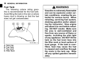
.... Tank Cap Fuel Tank Top Level Filler Neck If the tank is well-ventilated and free from any spilled gasoline immediately. Wipe off any source of flame or sparks, including the pilot light of level gauge. B. C. D. WARNING Gasoline is blowing so that the fuel does not get contaminated. When refueling, servicing fuel system, draining gasoline and/or adjusting the carburetor: Stop engine and...
.... Tank Cap Fuel Tank Top Level Filler Neck If the tank is well-ventilated and free from any spilled gasoline immediately. Wipe off any source of flame or sparks, including the pilot light of level gauge. B. C. D. WARNING Gasoline is blowing so that the fuel does not get contaminated. When refueling, servicing fuel system, draining gasoline and/or adjusting the carburetor: Stop engine and...

Owners Manual
Page 75
... between level lines (when engine is cold). Engine Stop Switch ...Stops engine. Nuts, Bolts, Fasteners Check that steering and suspension components, axles, and all controls are properly tightened or fastened. Steering ...Action smooth but not loose from lock to lock. No brake fluid leakage. Clutch lever operates smoothly. Electrical Equipment ...All lights (Headlight, City Light, Tail/Brake Lights, Turn Signal Lights, License Plate Light, Warning/Indicator Lights) and horn work. SAFE OPERATION 73 Tires ...Air pressure (when cold): Front Rear 225 kPa (2.25 kgf/cm²...
... between level lines (when engine is cold). Engine Stop Switch ...Stops engine. Nuts, Bolts, Fasteners Check that steering and suspension components, axles, and all controls are properly tightened or fastened. Steering ...Action smooth but not loose from lock to lock. No brake fluid leakage. Clutch lever operates smoothly. Electrical Equipment ...All lights (Headlight, City Light, Tail/Brake Lights, Turn Signal Lights, License Plate Light, Warning/Indicator Lights) and horn work. SAFE OPERATION 73 Tires ...Air pressure (when cold): Front Rear 225 kPa (2.25 kgf/cm²...

Owners Manual
Page 77
... the headlight, tail/brake light, turn signal lights, license plate light, horn, etc., all work properly. Miscellaneous: Make sure that all safety related parts are correctly adjusted and functioning properly. Fuel: Have sufficient fuel for High Speed Operation Brakes: The importance of the brakes, especially during high speed operation. SAFE OPERATION 75 Additional Considerations for the high fuel consumption during high speed operation, cannot be overemphasized. Engine Oil: To avoid engine seizure...
... the headlight, tail/brake light, turn signal lights, license plate light, horn, etc., all work properly. Miscellaneous: Make sure that all safety related parts are correctly adjusted and functioning properly. Fuel: Have sufficient fuel for High Speed Operation Brakes: The importance of the brakes, especially during high speed operation. SAFE OPERATION 75 Additional Considerations for the high fuel consumption during high speed operation, cannot be overemphasized. Engine Oil: To avoid engine seizure...

Owners Manual
Page 90
88 MAINTENANCE AND ADJUSTMENT Frequency Whichever comes first *Odometer Reading km × 1 000 (mile × 1 000) 1 6 12 18 24 30 36 (0.6) (3.75) (7.5) (11.25) (15) (18.75) (22.5) Operation (Chassis Items) Brake operation (effectiveness, play, drag) inspect Brake light switch operation - inspect Suspensions: Front forks/rear shock absorber operation (damping and smooth stroke) inspect See Page Every year • • • • • • • • • • • • • • • • • 131 132 134, 137
88 MAINTENANCE AND ADJUSTMENT Frequency Whichever comes first *Odometer Reading km × 1 000 (mile × 1 000) 1 6 12 18 24 30 36 (0.6) (3.75) (7.5) (11.25) (15) (18.75) (22.5) Operation (Chassis Items) Brake operation (effectiveness, play, drag) inspect Brake light switch operation - inspect Suspensions: Front forks/rear shock absorber operation (damping and smooth stroke) inspect See Page Every year • • • • • • • • • • • • • • • • • 131 132 134, 137
Owners Manual
Page 95
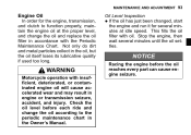
... If the oil has just been changed, start the engine and run it for the engine, transmission, and clutch to the periodic maintenance chart in the Owner's Manual. WARNING Motorcycle operation with oil. Stop the engine, then wait several minutes at the proper level, and change the oil according to function properly, maintain the engine oil at idle speed. This fills the oil filter with insufficient, deteriorated, or contaminated engine oil will cause accelerated...
... If the oil has just been changed, start the engine and run it for the engine, transmission, and clutch to the periodic maintenance chart in the Owner's Manual. WARNING Motorcycle operation with oil. Stop the engine, then wait several minutes at the proper level, and change the oil according to function properly, maintain the engine oil at idle speed. This fills the oil filter with insufficient, deteriorated, or contaminated engine oil will cause accelerated...

Owners Manual
Page 127
... there is exaggerated for installation; A. Worn Teeth C. the rear wheel to inspect the • Rotate drive chain for damaged rollers, and inspect the sprockets for wear limits. MAINTENANCE AND ADJUSTMENT 125 WARNING For safety, use only the standard chain. have the • If drive chain and/or the sprockets replaced by an authorized Kawasaki dealer. It is an endless type and should...
... there is exaggerated for installation; A. Worn Teeth C. the rear wheel to inspect the • Rotate drive chain for damaged rollers, and inspect the sprockets for wear limits. MAINTENANCE AND ADJUSTMENT 125 WARNING For safety, use only the standard chain. have the • If drive chain and/or the sprockets replaced by an authorized Kawasaki dealer. It is an endless type and should...

Owners Manual
Page 133
... front or rear brake is applied. the operation of the rear brake • Check light switch by depressing the brake pedal. The brake light should go on . The front brake light switch requires no adjustment, but the rear brake light switch should go on when the front brake is applied, the brake light goes on after the proper pedal travel. • • • A. Inspection Turn the ignition key to inspect the front brake light switch.
... front or rear brake is applied. the operation of the rear brake • Check light switch by depressing the brake pedal. The brake light should go on . The front brake light switch requires no adjustment, but the rear brake light switch should go on when the front brake is applied, the brake light goes on after the proper pedal travel. • • • A. Inspection Turn the ignition key to inspect the front brake light switch.

Owners Manual
Page 134
132 MAINTENANCE AND ADJUSTMENT Adjustment Disconnect the connector. • adjust the rear brake light switch, • To move the switch up or down by turning the switch body. Rear Brake Light Switch Adjusting Nut Lights sooner Lights later • Connect the connector. C. A. B. D. Connector A.
132 MAINTENANCE AND ADJUSTMENT Adjustment Disconnect the connector. • adjust the rear brake light switch, • To move the switch up or down by turning the switch body. Rear Brake Light Switch Adjusting Nut Lights sooner Lights later • Connect the connector. C. A. B. D. Connector A.
Owners Manual
Page 159
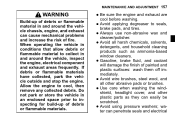
Do not park or store the vehicle in conditions that allow debris or flammable material to seals, • Avoid brake pads, and tires. Use care when washing the windshield, headlight cover, and other abrasive pads or brushes. water can easily be scratched. use non-abrasive wax and • Always cleaner/polisher. Avoid wire brushes, steel wool, and all harsh chemicals, solvents, • Avoid...
Do not park or store the vehicle in conditions that allow debris or flammable material to seals, • Avoid brake pads, and tires. Use care when washing the windshield, headlight cover, and other abrasive pads or brushes. water can easily be scratched. use non-abrasive wax and • Always cleaner/polisher. Avoid wire brushes, steel wool, and all harsh chemicals, solvents, • Avoid...
Owners Manual
Page 171
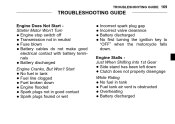
... left down Clutch does not properly disengage • Engine Cranks, But Won't Start fuel in tank • No tank air vent is obstructed • Fuel • Overheating • Battery discharged TROUBLESHOOTING GUIDE 169 TROUBLESHOOTING GUIDE Engine Does Not Start Starter Motor Won't Turn Engine stop switch off Transmission not in neutral Fuse blown Battery cables do not make good electrical contact with battery terminals Battery discharged spark plug gap • Incorrect Incorrect valve clearance • Battery discharged • No first turning the ignition key to...
... left down Clutch does not properly disengage • Engine Cranks, But Won't Start fuel in tank • No tank air vent is obstructed • Fuel • Overheating • Battery discharged TROUBLESHOOTING GUIDE 169 TROUBLESHOOTING GUIDE Engine Does Not Start Starter Motor Won't Turn Engine stop switch off Transmission not in neutral Fuse blown Battery cables do not make good electrical contact with battery terminals Battery discharged spark plug gap • Incorrect Incorrect valve clearance • Battery discharged • No first turning the ignition key to...
