Owner's Manual
Page 71
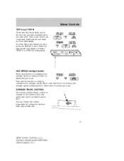
... in miles per hour or TRIP TRIP AVG kilometers per hour. INTERIOR TRUNK CONTROL The remote trunk release control is located on the driver's door trim panel and can render the switch inoperable by locking the button with your vehicle is not moving to zero, press the RESET control while the appropriate... two functions allow you to display your average speed. Trip A and Trip B are completely independent and must be reset individually. When your master key. 71 2004 Crown Victoria (cro) Owners Guide (post-2002-fmt) USA English (fus)
... in miles per hour or TRIP TRIP AVG kilometers per hour. INTERIOR TRUNK CONTROL The remote trunk release control is located on the driver's door trim panel and can render the switch inoperable by locking the button with your vehicle is not moving to zero, press the RESET control while the appropriate... two functions allow you to display your average speed. Trip A and Trip B are completely independent and must be reset individually. When your master key. 71 2004 Crown Victoria (cro) Owners Guide (post-2002-fmt) USA English (fus)
Owner's Manual
Page 76
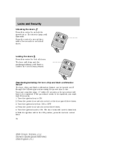
...Turn the ignition key to be repeated, you must complete steps 1-7 within five seconds to unlock all doors. With the ignition still in the ON position, press the unlock control twice. 76 2004 Crown Victoria (cro) Owners Guide (post-2002-fmt) USA English (fus) Press the control a second time within...feature The horn chirp and flash confirmation feature can be repeated. Turn the ignition back to be turned on the door panel three times. 3. Locks and Security Unlocking the doors Press this control to unlock the driver's door. Press the power door unlock control three times. 5.
...Turn the ignition key to be repeated, you must complete steps 1-7 within five seconds to unlock all doors. With the ignition still in the ON position, press the unlock control twice. 76 2004 Crown Victoria (cro) Owners Guide (post-2002-fmt) USA English (fus) Press the control a second time within...feature The horn chirp and flash confirmation feature can be repeated. Turn the ignition back to be turned on the door panel three times. 3. Locks and Security Unlocking the doors Press this control to unlock the driver's door. Press the power door unlock control three times. 5.

Owner's Manual
Page 80
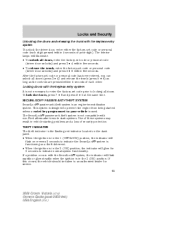
If the procedure needs to be turned on/off if: • they have to be repeated, you shift into any door is entered/active. 80 2004 Crown Victoria (cro) Owners Guide (post-2002-fmt) USA English (fus) Turn the ignition back to ON. 2. Turn the ignition key to ON....steps 1-7 within 30 seconds or the procedure will have been turned on the door panel three times. 3. Autolock (if equipped) This feature automatically locks all vehicle doors when: • all vehicle doors are closed . Press the power door unlock control on with the dimmer control, or • any gear. Press...
If the procedure needs to be turned on/off if: • they have to be repeated, you shift into any door is entered/active. 80 2004 Crown Victoria (cro) Owners Guide (post-2002-fmt) USA English (fus) Turn the ignition back to ON. 2. Turn the ignition key to ON....steps 1-7 within 30 seconds or the procedure will have been turned on the door panel three times. 3. Autolock (if equipped) This feature automatically locks all vehicle doors when: • all vehicle doors are closed . Press the power door unlock control on with the dimmer control, or • any gear. Press...
Owner's Manual
Page 83
THEFT INDICATOR The theft indicator is the flashing red indicator located on the dash panel. • When the ignition is in the 1 (OFF/LOCK) position, the indicator will flash rapidly or glow steadily when the ignition is an engine ...SecuriLock passive anti-theft system is used. The interior lamps will glow for service. 83 2004 Crown Victoria (cro) Owners Guide (post-2002-fmt) USA English (fus) Locks and Security Unlocking the doors and releasing the trunk with non-Ford aftermarket remote start systems. Use of these systems may result in vehicle starting problems and...
THEFT INDICATOR The theft indicator is the flashing red indicator located on the dash panel. • When the ignition is in the 1 (OFF/LOCK) position, the indicator will flash rapidly or glow steadily when the ignition is an engine ...SecuriLock passive anti-theft system is used. The interior lamps will glow for service. 83 2004 Crown Victoria (cro) Owners Guide (post-2002-fmt) USA English (fus) Locks and Security Unlocking the doors and releasing the trunk with non-Ford aftermarket remote start systems. Use of these systems may result in vehicle starting problems and...
Owner's Manual
Page 111
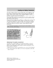
...bags are fitted on the side affected by a qualified technician in side impact collisions. The air bag was designed to inflate between the door panel and occupant to cause activation. Rather, it means the forces were not of the type sufficient to further enhance the protection provided occupants in...manual. The side air bag system (including the seat) must be inspected and serviced by the collision will either flash or stay lit. 111 2004 Crown Victoria (cro) Owners Guide (post-2002-fmt) USA English (fus) Seating and Safety Restraints The side air bags are designed to close an ...
...bags are fitted on the side affected by a qualified technician in side impact collisions. The air bag was designed to inflate between the door panel and occupant to cause activation. Rather, it means the forces were not of the type sufficient to further enhance the protection provided occupants in...manual. The side air bag system (including the seat) must be inspected and serviced by the collision will either flash or stay lit. 111 2004 Crown Victoria (cro) Owners Guide (post-2002-fmt) USA English (fus) Seating and Safety Restraints The side air bags are designed to close an ...
Owner's Manual
Page 150
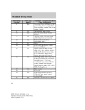
Roadside Emergencies Fuse/Relay Location 8 Fuse Amp Rating 25A Passenger Compartment Fuse Panel Description Powertrain Control Module (PCM) power relay, Coil-on plugs, Radio noise capacitor, ...Brake System (ABS), Instrument Cluster Speed control module, Power relay coil (Police vehicle option), LCM, EATC blower motor relay, Door lock switch illumination, Heated seat switch, Moonroof Reversing lamps, Shift lock, DRL module, VAP Steering, Electronic day/night mirror,...15A 5A 10A 15A 16 15A 17 18 19 7.5A - 15A 20 20A 150 2004 Crown Victoria (cro) Owners Guide (post-2002-fmt) USA English (fus)
Roadside Emergencies Fuse/Relay Location 8 Fuse Amp Rating 25A Passenger Compartment Fuse Panel Description Powertrain Control Module (PCM) power relay, Coil-on plugs, Radio noise capacitor, ...Brake System (ABS), Instrument Cluster Speed control module, Power relay coil (Police vehicle option), LCM, EATC blower motor relay, Door lock switch illumination, Heated seat switch, Moonroof Reversing lamps, Shift lock, DRL module, VAP Steering, Electronic day/night mirror,...15A 5A 10A 15A 16 15A 17 18 19 7.5A - 15A 20 20A 150 2004 Crown Victoria (cro) Owners Guide (post-2002-fmt) USA English (fus)
Owner's Manual
Page 151
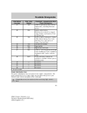
Always disconnect the battery before servicing high current fuses. 151 2004 Crown Victoria (cro) Owners Guide (post-2002-fmt) USA English (fus) Roadside Emergencies Fuse/Relay Location 21 Fuse Amp Rating 15A Passenger Compartment Fuse Panel Description LCM for park lamps and interior illumination, Autolamp/Sunload sensor Speed ...-hand low beam LCM for cornering lamps and high beam headlamps, Police headlamp wigwag module (police vehicles only) Power windows, Instrument panel/Door decklid release (police vehicles only) Not used Not used Not used Not used 22 20A 23 15A 24 25 26 27 10A...
Always disconnect the battery before servicing high current fuses. 151 2004 Crown Victoria (cro) Owners Guide (post-2002-fmt) USA English (fus) Roadside Emergencies Fuse/Relay Location 21 Fuse Amp Rating 15A Passenger Compartment Fuse Panel Description LCM for park lamps and interior illumination, Autolamp/Sunload sensor Speed ...-hand low beam LCM for cornering lamps and high beam headlamps, Police headlamp wigwag module (police vehicles only) Power windows, Instrument panel/Door decklid release (police vehicles only) Not used Not used Not used Not used 22 20A 23 15A 24 25 26 27 10A...
Owner's Manual
Page 232
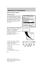
...FORD MOTOR CO. Vehicle line, series, body type 4. Assembly plant 8. World manufacturer identifier 2. Check digit 6. IN U.S.A. Engine type 5. Maintenance and Specifications IDENTIFYING YOUR VEHICLE Certification label The National Highway Traffic Safety Administration Regulations require that in the graphic XXXX is located on the front door latch pillar on the driver side instrument panel...and prescribe where the Certification label may be located. Production sequence number 232 2004 Crown Victoria (cro) Owners Guide (post-2002-fmt) USA English (fus) The Certification label ...
...FORD MOTOR CO. Vehicle line, series, body type 4. Assembly plant 8. World manufacturer identifier 2. Check digit 6. IN U.S.A. Engine type 5. Maintenance and Specifications IDENTIFYING YOUR VEHICLE Certification label The National Highway Traffic Safety Administration Regulations require that in the graphic XXXX is located on the front door latch pillar on the driver side instrument panel...and prescribe where the Certification label may be located. Production sequence number 232 2004 Crown Victoria (cro) Owners Guide (post-2002-fmt) USA English (fus) The Certification label ...

Owner's Manual
Page 239
... ...202 running out of fuel ...202 safety information relating to automotive fuels ...198 Fuses ...147-148 G Garage Door Opener (see Homelink wireless control system) ...64 Gas cap (see Fuel cap) ...200 Gas mileage (see Fuel...door opener) ...54, 67 Homelink wireless control system ...64 Hood ...184 I Ignition ...124, 230 Infant seats (see Safety seats) ...115 Inspection/maintenance (I/M) testing ...208 Instrument panel cleaning ...180 cluster ...10 lighting up panel and interior ...39 J Jack ...155 positioning ...155 storage ...155 Jump-starting your vehicle ...161 239 2004 Crown Victoria...
... ...202 running out of fuel ...202 safety information relating to automotive fuels ...198 Fuses ...147-148 G Garage Door Opener (see Homelink wireless control system) ...64 Gas cap (see Fuel cap) ...200 Gas mileage (see Fuel...door opener) ...54, 67 Homelink wireless control system ...64 Hood ...184 I Ignition ...124, 230 Infant seats (see Safety seats) ...115 Inspection/maintenance (I/M) testing ...208 Instrument panel cleaning ...180 cluster ...10 lighting up panel and interior ...39 J Jack ...155 positioning ...155 storage ...155 Jump-starting your vehicle ...161 239 2004 Crown Victoria...

Owner's Manual
Page 240
... Lamps autolamp system ...38 bulb replacement specifications chart ...41 daytime running light ...38 headlamps ...38 headlamps, flash to pass ...39 instrument panel, dimming ...39 interior lamps ...40-41 replacing bulbs ...41-46 Lane change indicator (see Turn signal) ...40 Lights, warning and ...see Fuses) ...151 Power door locks ...73, 80 Power mirrors ...58 Power Point Cigar lighter ...56 Power steering ...132-133 fluid, checking and adding ...208 fluid, refill capacity ...227 fluid, specifications ...228 Power Windows ...57 R Radio ...20, 23, 26, 28 2004 Crown Victoria (cro) Owners Guide ...
... Lamps autolamp system ...38 bulb replacement specifications chart ...41 daytime running light ...38 headlamps ...38 headlamps, flash to pass ...39 instrument panel, dimming ...39 interior lamps ...40-41 replacing bulbs ...41-46 Lane change indicator (see Turn signal) ...40 Lights, warning and ...see Fuses) ...151 Power door locks ...73, 80 Power mirrors ...58 Power Point Cigar lighter ...56 Power steering ...132-133 fluid, checking and adding ...208 fluid, refill capacity ...227 fluid, specifications ...228 Power Windows ...57 R Radio ...20, 23, 26, 28 2004 Crown Victoria (cro) Owners Guide ...

Severe Duty Supplement 1st Printing
Page 17
The air bag door must not interfere with driver visibility. 2. Area in front of center console from bottom of ashtray to top of air bag 3. Area on ashtray door. 17 Equipment must be kept clear for deployment of instrument panel (see Figure 2 for dimensions) 4. 279 mm (11 inches) width horizontally centered on top of instrument panel. Air Bag Information 1 2 50 40 60 80 60 70 100 120 80 140 90 160 30 40 100 110 120 L 20 10 180 20 200 P RND21 4 3 Figure 6 1.
The air bag door must not interfere with driver visibility. 2. Area in front of center console from bottom of ashtray to top of air bag 3. Area on ashtray door. 17 Equipment must be kept clear for deployment of instrument panel (see Figure 2 for dimensions) 4. 279 mm (11 inches) width horizontally centered on top of instrument panel. Air Bag Information 1 2 50 40 60 80 60 70 100 120 80 140 90 160 30 40 100 110 120 L 20 10 180 20 200 P RND21 4 3 Figure 6 1.


