
Owner's Manual
Page 49
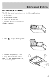
Entertainment Systems CD CHANGER (IF EQUIPPED) The CD changer is located in the center console • under the driver's seat 1. Press to access the CD changer magazine. 2. A B C 49 Using the disc holder release knob (C), pull the disc holder (B) out of the following locations: • in the trunk • in one of the magazine. Turn the magazine (A) over. 4. Slide the door to eject the magazine. 3.
Entertainment Systems CD CHANGER (IF EQUIPPED) The CD changer is located in the center console • under the driver's seat 1. Press to access the CD changer magazine. 2. A B C 49 Using the disc holder release knob (C), pull the disc holder (B) out of the following locations: • in the trunk • in one of the magazine. Turn the magazine (A) over. 4. Slide the door to eject the magazine. 3.
Owner's Manual
Page 90
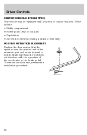
To remove the floor mat, reverse the installation procedure. 90 Make sure that the eyelet is over the pointed end of the retention post and rotate forward to the rear seating positions (heat only) POSITIVE RETENTION FLOOR MAT Position the floor mat so that the mat does not interfere with a variety of console features. Driver Controls CENTER CONSOLE (IF EQUIPPED) Your vehicle may be equipped with the operation of the accelerator or the brake pedal. These include: • Utility compartment • Power point (rear of console) • Cupholders • Air vents to lock in.
To remove the floor mat, reverse the installation procedure. 90 Make sure that the eyelet is over the pointed end of the retention post and rotate forward to the rear seating positions (heat only) POSITIVE RETENTION FLOOR MAT Position the floor mat so that the mat does not interfere with a variety of console features. Driver Controls CENTER CONSOLE (IF EQUIPPED) Your vehicle may be equipped with the operation of the accelerator or the brake pedal. These include: • Utility compartment • Power point (rear of console) • Cupholders • Air vents to lock in.
Owner's Manual
Page 234
... ...180 D Daytime running lamps (see Speed control) ...79 Customer Assistance ...156 Ford accessories for your vehicle engine compartment ...186 exterior ...189 instrument cluster lens ...188 instrument...25, 30, 36, 44 Compass, electronic ...77 calibration ...78 set zone adjustment ...77 Console ...90 Controls power seat ...106, 108 steering column ...83 Coolant checking and adding ...199 ... lubricant specifications ...226 Driving under special conditions through water ...150 E Electronic message center ...83 Emergencies, roadside jump-starting ...169 Emission control system ...213 Engine ...228...
... ...180 D Daytime running lamps (see Speed control) ...79 Customer Assistance ...156 Ford accessories for your vehicle engine compartment ...186 exterior ...189 instrument cluster lens ...188 instrument...25, 30, 36, 44 Compass, electronic ...77 calibration ...78 set zone adjustment ...77 Console ...90 Controls power seat ...106, 108 steering column ...83 Coolant checking and adding ...199 ... lubricant specifications ...226 Driving under special conditions through water ...150 E Electronic message center ...83 Emergencies, roadside jump-starting ...169 Emission control system ...213 Engine ...228...
Severe Duty Supplement 2nd Printing
Page 11
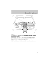
Area in front of center console from bottom of ashtray to top of instrument panel (see Figure 2 for deployment of instrument panel. Equipment must be kept clear for dimensions) 4. 279 mm (11 inches) width horizontally centered on top of air bag 3. Severe duty equipment 1 2 50 40 60 80 60 70 100 120 80 140 90 160 30 40 100 110 120 L 20 10 180 20 200 P RND21 4 3 Figure 4 1. Area on ashtray door. 11 The air bag door must not interfere with driver visibility. 2.
Area in front of center console from bottom of ashtray to top of instrument panel (see Figure 2 for deployment of instrument panel. Equipment must be kept clear for dimensions) 4. 279 mm (11 inches) width horizontally centered on top of air bag 3. Severe duty equipment 1 2 50 40 60 80 60 70 100 120 80 140 90 160 30 40 100 110 120 L 20 10 180 20 200 P RND21 4 3 Figure 4 1. Area on ashtray door. 11 The air bag door must not interfere with driver visibility. 2.
Severe Duty Supplement 2nd Printing
Page 12
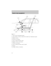
Prisoner screen 4. 254 mm (10 inches) 5. Area on tunnel beneath center console 9. Height: 216 mm (8.5 inches) 7. 305 mm (12 inches) 8. Area on tunnel between seats 6. Severe duty equipment 2 1 3 10 7 9 8 Figure 5 6 5 4 1. Area in front of instrument panel 2. Depth: 38 mm (1.5 inches) 12 Tunnel 10. Area on top of center console from tunnel up to instrument panel 3.
Prisoner screen 4. 254 mm (10 inches) 5. Area on tunnel beneath center console 9. Height: 216 mm (8.5 inches) 7. 305 mm (12 inches) 8. Area on tunnel between seats 6. Severe duty equipment 2 1 3 10 7 9 8 Figure 5 6 5 4 1. Area in front of instrument panel 2. Depth: 38 mm (1.5 inches) 12 Tunnel 10. Area on top of center console from tunnel up to instrument panel 3.


