Owner's Manual
Page 34
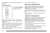
...the tailgate handle, rinse it with water and wipe it with a soft cloth. The indicator light is on when cruise control is on the rear bumper to the radio. To clean the camera lens, located in the bezel for more information, see Rear Vision Camera (RVC) on page 3‑63....on page 4‑7. See DIC Vehicle Customization (With DIC Buttons) on automatically when the shift lever is moved into R (Reverse) on the vehicle's rear bumper clean to disengage cruise control without erasing the set speed, or press and hold to provide distance and system information. See Cruise Control on or...
...the tailgate handle, rinse it with water and wipe it with a soft cloth. The indicator light is on when cruise control is on the rear bumper to the radio. To clean the camera lens, located in the bezel for more information, see Rear Vision Camera (RVC) on page 3‑63....on page 4‑7. See DIC Vehicle Customization (With DIC Buttons) on automatically when the shift lever is moved into R (Reverse) on the vehicle's rear bumper clean to disengage cruise control without erasing the set speed, or press and hold to provide distance and system information. See Cruise Control on or...
Owner's Manual
Page 134
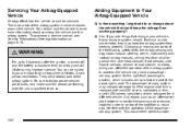
... system from working properly. Avoid yellow connectors. Adding Equipment to Your Airbag-Equipped Vehicle Q: Is there anything I might add to or change your vehicle's frame, bumper system, height, front end or side sheet metal, they may keep the airbags from working properly? A: Yes. Be sure to follow proper service procedures, and...
... system from working properly. Avoid yellow connectors. Adding Equipment to Your Airbag-Equipped Vehicle Q: Is there anything I might add to or change your vehicle's frame, bumper system, height, front end or side sheet metal, they may keep the airbags from working properly? A: Yes. Be sure to follow proper service procedures, and...
Owner's Manual
Page 198
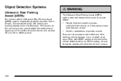
... not replace driver vision. While backing, be sure to 2.5 m (8 ft) behind the vehicle before and while backing; It cannot detect: . Objects that are below the bumper, underneath the vehicle, or if they are used to detect the distance to an object up . vehicle damage, injury, or death could occur. If you... assists the driver with the Ultrasonic Rear Parking Assist (URPA) system, it operates at least 25.4 cm (10 in R (Reverse). The sensors on the rear bumper are too close or far from the vehicle Children, pedestrians, bicyclists, or pets. .
... not replace driver vision. While backing, be sure to 2.5 m (8 ft) behind the vehicle before and while backing; It cannot detect: . Objects that are below the bumper, underneath the vehicle, or if they are used to detect the distance to an object up . vehicle damage, injury, or death could occur. If you... assists the driver with the Ultrasonic Rear Parking Assist (URPA) system, it operates at least 25.4 cm (10 in R (Reverse). The sensors on the rear bumper are too close or far from the vehicle Children, pedestrians, bicyclists, or pets. .
Owner's Manual
Page 199
... to the radio. URPA operates only at least 25.4 cm (10 in ) the beeps are continuous. The system can be within 2.5 m (8 ft) from the rear bumper. Notice: If you might back into R (Reverse). A single tone sounds to indicate the system is lowered, it may be at speeds less than 30 cm...
... to the radio. URPA operates only at least 25.4 cm (10 in ) the beeps are continuous. The system can be within 2.5 m (8 ft) from the rear bumper. Notice: If you might back into R (Reverse). A single tone sounds to indicate the system is lowered, it may be at speeds less than 30 cm...
Owner's Manual
Page 200
... system will not activate due to the vehicle. A tow bar is raised, URPA will be seen; Keep the vehicle's rear bumper free of air brakes on a very large truck. . . . The vehicle's bumper is still disabled, after washing the vehicle in cold weather. Take the vehicle to your dealer to repair the system...
... system will not activate due to the vehicle. A tow bar is raised, URPA will be seen; Keep the vehicle's rear bumper free of air brakes on a very large truck. . . . The vehicle's bumper is still disabled, after washing the vehicle in cold weather. Take the vehicle to your dealer to repair the system...

Owner's Manual
Page 201
... could be cross-traffic. The rear camera vision display is designed to help the driver when backing up by displaying a view of view, below the bumper, or underneath the vehicle. Rear Vision Camera (RVC) This vehicle may have a Rear Vision Camera system. The rear vision camera system display is in vehicle...
... could be cross-traffic. The rear camera vision display is designed to help the driver when backing up by displaying a view of view, below the bumper, or underneath the vehicle. Rear Vision Camera (RVC) This vehicle may have a Rear Vision Camera system. The rear vision camera system display is in vehicle...
Owner's Manual
Page 204
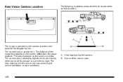
Corner of the rear bumper. 3-66 The distance of the image that the camera provides. B. The camera uses a special lens. The area displayed on the screen differs from the actual .... Rear Vision Camera Location The following illustration shows the field of view that appears on the screen can vary according to either corner of the bumper or under the bumper. A. View displayed by the camera located in the bezel for the tailgate handle.
Corner of the rear bumper. 3-66 The distance of the image that the camera provides. B. The camera uses a special lens. The area displayed on the screen differs from the actual .... Rear Vision Camera Location The following illustration shows the field of view that appears on the screen can vary according to either corner of the bumper or under the bumper. A. View displayed by the camera located in the bezel for the tailgate handle.

Owner's Manual
Page 216
... to be turned to RUN, or the Retained Accessory Power (RAP) must be sure it to spread the load. Also tie the load to the bumpers, but do not block or damage the CHMSL. 3-78 For more information on vehicle capacity and loading, see Loading the Vehicle on page 3‑23...
... to be turned to RUN, or the Retained Accessory Power (RAP) must be sure it to spread the load. Also tie the load to the bumpers, but do not block or damage the CHMSL. 3-78 For more information on vehicle capacity and loading, see Loading the Vehicle on page 3‑23...

Owner's Manual
Page 429
... will be adjusted so the distance (A) is ample room when turning to avoid contact between the trailer and the bumper. Weight‐Distributing Hitch Adjustment A: Body to the tow vehicle and adjusting the hitch. 5-63 Ask a trailering professional about sway controls or...equipment helps maintain combination control. See "Weight of Vehicle When using sway controls with various hitch types. Larger trailers may also be used , the bumper could be towed with a weight carrying hitch which simply features a coupler latched to -medium trailers can be damaged in this section for rating ...
... will be adjusted so the distance (A) is ample room when turning to avoid contact between the trailer and the bumper. Weight‐Distributing Hitch Adjustment A: Body to the tow vehicle and adjusting the hitch. 5-63 Ask a trailering professional about sway controls or...equipment helps maintain combination control. See "Weight of Vehicle When using sway controls with various hitch types. Larger trailers may also be used , the bumper could be towed with a weight carrying hitch which simply features a coupler latched to -medium trailers can be damaged in this section for rating ...
Owner's Manual
Page 430
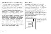
...off the tow/ haul mode. 5-64 Instructions about safety chains may be attached to the attaching points on the bumper, otherwise, safety chains should be 15 to 25 percent of the cab in this weight does not cause the vehicle to exceed GAWR or GVWR. Never allow safety chains to 5,000...shelf that it is over the box. Fifth Wheel and Gooseneck Trailering Fifth wheel and gooseneck trailers can be used with a factory-installed step bumper, safety chains may be provided by the hitch manufacturer or by the trailer manufacturer. Safety Chains Always attach chains between the top of the ...
...off the tow/ haul mode. 5-64 Instructions about safety chains may be attached to the attaching points on the bumper, otherwise, safety chains should be 15 to 25 percent of the cab in this weight does not cause the vehicle to exceed GAWR or GVWR. Never allow safety chains to 5,000...shelf that it is over the box. Fifth Wheel and Gooseneck Trailering Fifth wheel and gooseneck trailers can be used with a factory-installed step bumper, safety chains may be provided by the hitch manufacturer or by the trailer manufacturer. Safety Chains Always attach chains between the top of the ...
Owner's Manual
Page 506
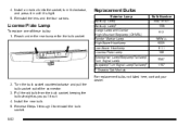
... a new bulb into the socket, turn it clockwise, and press it in until it out. 4. Install the new bulb. 5. Reach under the rear bumper for the bulb socket. Reverse Steps 1 through 3 to reinstall the bulb socket. 6-62 Replacement Bulbs Exterior Lamp Back-up Lamp Back-up Lamp* Cargo ...Marker Lamp High-Beam Headlamp Low-Beam Headlamp License Plate Lamp Sidemarker Lamp/Stoplamp/Taillamp/ Turn Signal Lamp Stoplamp/Turn Signal Lamp/Taillamp* * Chassis Cab Models Bulb Number 3047 or 921 1156 912 W5WLL 9005 H11 168 3047 1157 License Plate Lamp To replace one of the connector. 3. Turn ...
... a new bulb into the socket, turn it clockwise, and press it in until it out. 4. Install the new bulb. 5. Reach under the rear bumper for the bulb socket. Reverse Steps 1 through 3 to reinstall the bulb socket. 6-62 Replacement Bulbs Exterior Lamp Back-up Lamp Back-up Lamp* Cargo ...Marker Lamp High-Beam Headlamp Low-Beam Headlamp License Plate Lamp Sidemarker Lamp/Stoplamp/Taillamp/ Turn Signal Lamp Stoplamp/Turn Signal Lamp/Taillamp* * Chassis Cab Models Bulb Number 3047 or 921 1156 912 W5WLL 9005 H11 168 3047 1157 License Plate Lamp To replace one of the connector. 3. Turn ...

Owner's Manual
Page 532
..., wheel bolts, wheel nuts or Tire Pressure Monitor System (TPMS) sensors, replace them only with bearing life, brake cooling, speedometer or odometer calibration, headlamp aim, bumper height, vehicle ground clearance, and tire or tire chain clearance to replace a wheel, use the correct wheel, wheel bolts, and wheel nuts for replacement. Used...
..., wheel bolts, wheel nuts or Tire Pressure Monitor System (TPMS) sensors, replace them only with bearing life, brake cooling, speedometer or odometer calibration, headlamp aim, bumper height, vehicle ground clearance, and tire or tire chain clearance to replace a wheel, use the correct wheel, wheel bolts, and wheel nuts for replacement. Used...
Owner's Manual
Page 538
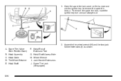
Spare Tire (Valve Stem Pointed Down) B. Hoist Shaft F. Hoist Shaft Access Hole H. Hoist Assembly C. Assemble the wheel wrench (H) and the two jack handle extensions (I . To remove the spare tire lock, insert the ignition key turn and pull straight out. Tire/Wheel Retainer E. Jack Handle Extensions J. A. Hoist Cable D. Spare Tire Lock (If equipped) 2. Hoist End of Extension Tool G. 1. Open the spare tire lock cover on the bumper and use the ignition key to remove the spare tire lock (J). Wheel Wrench I ) as shown. 6-94
Spare Tire (Valve Stem Pointed Down) B. Hoist Shaft F. Hoist Shaft Access Hole H. Hoist Assembly C. Assemble the wheel wrench (H) and the two jack handle extensions (I . To remove the spare tire lock, insert the ignition key turn and pull straight out. Tire/Wheel Retainer E. Jack Handle Extensions J. A. Hoist Cable D. Spare Tire Lock (If equipped) 2. Hoist End of Extension Tool G. 1. Open the spare tire lock cover on the bumper and use the ignition key to remove the spare tire lock (J). Wheel Wrench I ) as shown. 6-94

Owner's Manual
Page 539
... 6‑103. 5. The ribbed square end of the wheel wrench. 4. Turn the wheel wrench (H) counterclockwise to lower the spare tire to assist in the rear bumper. Use the wheel wrench hook which allows you to pull the hoist cable towards you to the ground. Continue to turn the wheel wrench until...
... 6‑103. 5. The ribbed square end of the wheel wrench. 4. Turn the wheel wrench (H) counterclockwise to lower the spare tire to assist in the rear bumper. Use the wheel wrench hook which allows you to pull the hoist cable towards you to the ground. Continue to turn the wheel wrench until...
Owner's Manual
Page 548
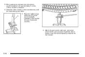
Stand the wheel blocks on the wheel blocks (B), separating them so that the jack is exposed. 6. Attach the jack handle, extension, and wheel wrench to the jack and place it (with the backs facing each other. 7. 5. Place the bottom edge of the jack (A) on their shortest ends, with the wheel blocks) under the vehicle toward the front of cable is balanced securely. 8. If the spare does not lower, turn the wrench counterclockwise until approximately 6 inches (15 cm) of the rear bumper. 6-104
Stand the wheel blocks on the wheel blocks (B), separating them so that the jack is exposed. 6. Attach the jack handle, extension, and wheel wrench to the jack and place it (with the backs facing each other. 7. 5. Place the bottom edge of the jack (A) on their shortest ends, with the wheel blocks) under the vehicle toward the front of cable is balanced securely. 8. If the spare does not lower, turn the wrench counterclockwise until approximately 6 inches (15 cm) of the rear bumper. 6-104

Owner's Manual
Page 549
..., see Removing the Flat Tire and Installing the Spare Tire on the jack. 12. Turn the wheel wrench in the hoist shaft hole in the bumper and turn the wheel wrench counterclockwise to lower the spare the rest of extension, and wheel wrench into the hoist shaft hole in the... bumper clockwise to raise the cable back up if the cable is behind you or on either side of the spare tire. 10. Keep lowering the ...
..., see Removing the Flat Tire and Installing the Spare Tire on the jack. 12. Turn the wheel wrench in the hoist shaft hole in the bumper and turn the wheel wrench counterclockwise to lower the spare the rest of extension, and wheel wrench into the hoist shaft hole in the... bumper clockwise to raise the cable back up if the cable is behind you or on either side of the spare tire. 10. Keep lowering the ...
Owner's Manual
Page 551
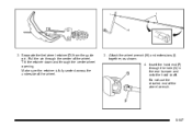
Pull the pin through the hole (G) in the rear bumper and onto the hoist shaft. Insert the hoist end (F) through the center of the wheel. Make sure the retainer is fully seated across the underside of the wheel wrench. 6-107 Do not use the chiseled end of the wheel. 3. 2. Tilt the retainer down and through the center wheel opening. Separate the tire/wheel retainer (D) from the guide pin. Attach the wheel wrench (H) and extensions (I) together, as shown. 4.
Pull the pin through the hole (G) in the rear bumper and onto the hoist shaft. Insert the hoist end (F) through the center of the wheel. Make sure the retainer is fully seated across the underside of the wheel wrench. 6-107 Do not use the chiseled end of the wheel. 3. 2. Tilt the retainer down and through the center wheel opening. Separate the tire/wheel retainer (D) from the guide pin. Attach the wheel wrench (H) and extensions (I) together, as shown. 4.
