Sony STR-K790 Support Question
Sony STR-K790 Support Question
Find answers below for this question about Sony STR-K790 - Lifier.Need a Sony STR-K790 manual? We have 1 online manual for this item!
Question posted by feletimatagi on January 11th, 2011
What Does Error 12 Push Enter Mean?
i put the av inputs into the tv av then connected everything but i get a message of "error 12" "push enter." what does mean?
Current Answers
Related Sony STR-K790 Manual Pages
Service Manual - Page 2
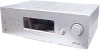
...CRITIQUES POUR LA SÉCURITÉ DE FONCTIONNEMENT. STR-K790
Power consumption
Area code
Power consumption
US
210 W
Canadian...× 145 × 308 mm (16 7/8 × 5 6/8 × 12 1/8 inches) including projecting parts and controls
Mass (Approx.) 7.4 kg (16 lb...COMPONENT WARNING!!
A commercial leakage tester, such as described below. Ordinary soldering irons can be measured by means...
Service Manual - Page 3
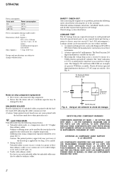
...MODEL IDENTIFICATION - ELECTRICAL ADJUSTMENT 12
4. Printed Wiring Board - MAIN Board 25 4-13. Schematic Diagram - DISPLAY Board 31 4-19. Front Panel Section 42 5-2.
GENERAL 4
2. DIAGRAMS 13 4-1. MAIN Section 14 4-2. Printed Wiring Board - Printed Wiring Board - MAIN Board (1/4 27 4-15. MAIN Board (4/4 30 4-18. Printed Wiring Boards - STR-K790
About area codes
The...
Service Manual - Page 5
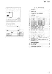
...Lights up when audio signal is decoding...Input, Preset Memory, etc., is activated. "; The boxes around the letters vary to 2 channel signals in radio stations, etc. Front Left Front Right Center (monaural) Surround Left Surround Right Surround (monaural or the surround components obtained by Pro Logic processing) Example: Recording format (Front/ Surround): 3/2.1 Sound Field: A.F.D. "; STR-K790...
Service Manual - Page 6
... the AM loop antenna supplied with this receiver. STR-K790
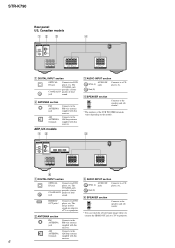
Rear panel US, Canadian models
12
3
4
DIGITAL OPTICAL
VIDEO 2/ BD IN COAXIAL DVD IN
ANTENNA AM
L
R AUDIO IN AUDIO IN AUDIO IN SA-CD/CD TV SAT
RL
SUB
RL
WOOFER SURROUND
SPEAKERS
RL
RL CENTER FRONT SPEAKERS
A DIGITAL INPUT section
OPTICAL Connects to a DVD
IN jack
player, etc.
Service Manual - Page 7
... direct sunlight
or lighting apparatuses.
Button
Assigned Sony component
VIDEO 1 VCR (VTR mode 3)
VIDEO 2 VCR (VTR mode 2)
VIDEO 3 Not assigned
DVD
DVD player
SAT
Satellite tuner
TV
Television
SA-CD/CD Super Audio CD/CD player
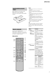
TUNER Built-in the RM-AAU013 remote commander. STR-K790
Inserting batteries into the remote
Insert two R6 (size...
Service Manual - Page 8
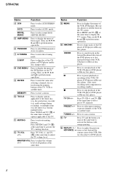
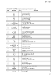
...TV channels. MOVIE, MUSIC
Press to enter direct tuning mode. G D.TUNING
Press to select sound fields (MOVIE, MUSIC). H DVD MENU
Press to the TV.
audio settings during recording), or multiple items on the TV...
function.
STR-K790
Name
Function
D 2CH
Press to select FM monaural or stereo reception. Then, use V, v, B, b and to search tracks in
recording standby.)
x TV CH +/-...
Service Manual - Page 9
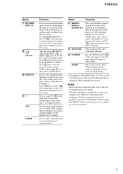
... disc player or DVD player. Press TV INPUT and TV (O) at the same time to select the TV channels. Press to select track number 10.
Then, press to enter the selection for receiver operation.
9 Use the tactile dots as an example only. Press 0/10 to activate the Auto Calibration function. STR-K790
Name
Q RETURN/ EXIT O
R V/v/B/b
S DISPLAY
T -/->10...
Service Manual - Page 11
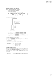
... board Checking Connect front left speaker, and the display will show :
"DCAC[][][]x" x = 1, 2, 3 If there is error happen, below display will show :
"ERR[]SD0x"
x = 1 → D1501 or R1530 x = 2 → D1502 problem x = 3 → D1503 problem
2. Turn MASTER VOLUME jog, there will be test tone sound output from front left speaker of test tone)
STR-K790
11...
Service Manual - Page 12
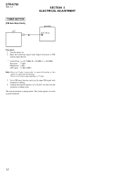
.... You cannot use 75 ohm "coaxial cable" to connect SG and the set. Input the following signal from Signal Generator to FM tuner function and scan the input FM signal with automatic scanning.
4. Confirm that input Frequency of automatic scanning means "The station signal is 75 ohm.
3. STR-K790
Ver. 1.1
TUNER SECTION [FM Auto Stop Check]
SET...
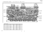
Service Manual - Page 15
...STR-K790
• R-CH is omitted due to same as L-CH. • Signal Path
: FM
L
IC501 POWER AMP
+V OUT2 12
8 IN2 NF2 9
Q501,502 LIMITER
Q503 BOOSTER
-V OUT2 11
IC601 POWER AMP
+V OUT2 12... -B
+B
-B
FL101 -20V
TUNER +10V RELAY +B AUDIO +7V
AUDIO +5V
AUDIO -7V
Q851,852 -B
SWITCH
D811
Q801 -20V REG
...48
32 31
POWER_RY 58 56
32 ENCODER
RV101
INPUT SELECTOR
S152 ?/1
HDMI +5.8V
+5V
+3.3V +2....
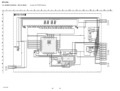
Service Manual - Page 21

...) CL029
13 +5V
12 VOL_JOG_2A
11 VOL_JOG_2B
10 PW_SW
9 SIRCS
8 AD2
7 AD1 CL030
6 FL_LAT CL031
5 FL_DIN CL032
4 FL_CLK
3 INPUT_JOG_4A
2 INPUT-JOG_4B
1 CNS513
17P
DCAC_IN...
H
DISPLAY BOARD CNS102 (Page 32)
No mark:FM
G
90 89 b9 91 92 97 99 93 94 95 96 98
a1 a2
a5 a4 a6 a3 a7 a8 b8 a9 b1 b2 b3
b5 b4 b6 b7
14
DIGITAL BOARD (5/5)
(Page 22)
STR-K790...
Service Manual - Page 23

No. IC5001 IC5002 IC5003 IC5004 IC5005 IC5006
Location
C-3 C-4 C-4 B-4 B-4 C-2
1
F
STR-K790
B199
1-873-511-
23
23
STR-K790 4-10.
PRINTED WIRING BOARDS - HDMI SW BOARD, HDMI BRIDGE BOARD (AEP, UK only) - • See page 13 for ...
R5061
R5060 R5014 R5029
D
HDMI BRIDGE BOARD
13
12
CNS199
E
6
CN199
1
A
DIGITAL BOARD CNS509 (Page 17)
2
• Semiconductor Location
Ref.
Service Manual - Page 24
...AEP, UK only) - • See page 37 for IC Block Diagrams.
AEP,UK VIDEO 2/BD IN
STR-K790
HDMI SW BOARD
R5047 0
R5068 100k
TP5016
R5016 0
R5017 0
CN5001 19P
CN5002 19P R5048 0
R5069 ...C5005 0.01
C5001 0.1
R5055 10k
R5060 0
R5024 0
R5072 100
HDMI BRIDGE BOARD
CN199 7P 1 2
CL199 3 4 5 6
CNS199 13P 13 12 11 10 9 8 7 6 5 4 3 2 1
HDMI 6.8V S1(HDMI) GND(NC) OED(HDMI) PRE(HDMI) CTL(HDMI)
COMP ...
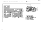
Service Manual - Page 25
No. No. PRINTED WIRING BOARD -
STR-K790
Ver. 1.1
1 A
B
C
DCAC
E BOARD
CN2001 (4pin-6pin) (Page 33)
D DIGITAL
F BOARD
CNS501 (Page 17)
E
DIGITAL
G F BOARD CNS502 (Page 17)
G
H
2
3
4
5
6
7
8
9
10
11
12
13
14
15
SA-CD/CD AUDIO IN
J400 TV AUDIO IN
SAT AUDIO IN
MAIN BOARD
AEP,UK
JW853
CC54
C452 C402
R454
TP1
DCAC
BOARD
B CN2001 (7pin-9pin...
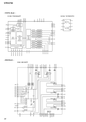
Service Manual - Page 32
STR-K790
4-19. SCHEMATIC DIAGRAM - DISPLAY BOARD -
• See page 38 for IC Block Diagrams.
1 A
B
C
D
E
F
G
H
K
POWER
BOARD
CNP152
I
(Page 34)
2
3
4
5
6
7
8
9
10
11
12
13
14
15
16
DISPLAY BOARD
FL101 FLUORESCENT INDICATOR TUBE
2 R199
2.2
5 6 7 8 9 10 11 12... CL105 CL106
2
C151 0.1
1
1
MASTER VOLUME
INPUT SELECTOR
RV101
3
2
3
C106 2200p
CL107 CL108 ...
Service Manual - Page 33
... 1-872-423- (11)
J790 PHONES
STR-K790
33
33 PRINTED WIRING BOARDS - STR-K790
1
2
3
A POWER BOARD
B
C
S152
D
JW123 JW122 JW121
E
F
G
JW124 JW126 JW125
4
5
6
7
8
9
CNP152
1
3
JW157
S114 DIMMER
R135 S115
R136
S116
SLEEP
2CH
K
DISPLAY BOARD CN101 (Page 31)
10
11
12
13
14
15
DCAC BOARD
J2000 VIDEO 1 IN/ PORTABLE AUDIO IN/ AUTO CAL MIC
JW2013...
Service Manual - Page 36
DAC
LEVEL
DELTA- STR-K790
-
MAIN Board - IC1452 PCM1602APT
ML MC MDI MDO ZERO8 DATA4 ZERO7 NC VCC1 AGND1 VCC2 AGND2
RST... CIN SWIN GND GND DATA CLOCK DVDD AVCC GND
5 Input selector
GND 1
INL5 2 INR5 3 INL4 4 INR4 5 INL3 6 INR3 7 INL2 8 INR2 9 INL1 10
5 Input selector
INR1 11 AVEE 12 ADIFL 13
ADIFR 14
15
Input ATT (for ADC)
Input ATT (for ADC)
16 17
Volume
Volume Volume
Volume ...
Service Manual - Page 38

DISPLAY Board - STR-K790
- IC100 PT6315
VSS VDD GRID1 GRID2 GRID3 GRID4 SEG24/GRID5 SEG23/GRID6 SEG22/GRID7 SEG21/GRID8 SEG20/GRID9
LED1 1 LED2 2 LED3 3 LED4 4
4-bit latch
44 43
42 41 40 39 Grid driver
Command decoder
Display memory 24 bits x 12 words
38 37 36 35 34
Multiplexed driver
33 SEG19/GRID10...
Service Manual - Page 39
... SD MODEL VAX CTRL
I/O
Description
I Audio data signal input from DIR
I GP9 signal input from DSP
O BST signal output to DSP
O HCS signal output to DSP
I HACN signal input from DSP
O HDIN signal output to DSP
O Clock signal output to DAC and ADC
- Analog power supply (+3.3V) I Vacs control input
STR-K790 39 Power supply (+3.3V)
O Composite...
Service Manual - Page 44
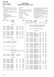
...J2000 1-820-056-11 SMALL TYPE JACK (VIDEO 1 IN/PORTABLE AUDIO IN/AUTO CAL MIC)
< TRANSISTOR >
R2018 1-249-418-11 ...STR-K790
DCAC DIGITAL
SECTION 6 ELECTRICAL PARTS LIST
NOTE: • Due to standardization, replacements in the
parts list may have some difference from the original one. • RESISTORS All resistors are in the diagrams or the components used on the set. • -XX and -X mean...
Similar Questions

Sony Str-k685,sale Error 12
tengo un equipo sony ,modelo : str - k685,mucho zumba los woofer y cuando calibro los parlantes sale...
tengo un equipo sony ,modelo : str - k685,mucho zumba los woofer y cuando calibro los parlantes sale...
(Posted by cesargoca 2 years ago)

What's The Value Of A Sony Audio Video Str-k7000
(Posted by lildch 10 years ago)

How Do You Remove A Protect Message From Sony Str K790
(Posted by hujcflye 10 years ago)

How Do I Set Stations On My Sony Digital Audio Str-k790
I purchased this audio receiver used from a garage sale and no longer have the remote. I set up a un...
I purchased this audio receiver used from a garage sale and no longer have the remote. I set up a un...
(Posted by thayerangel 10 years ago)

My Sony Multi-channel Av Receiver Str-k1600 Displays Error 12
It does not produce sound but everything is connected well. it only produces a very high shhhhhhh so...
It does not produce sound but everything is connected well. it only produces a very high shhhhhhh so...
(Posted by uthusi4sure 11 years ago)