
Sharp XL-HP515 Support Question
Sharp XL-HP515 Support Question
Find answers below for this question about Sharp XL-HP515.Need a Sharp XL-HP515 manual? We have 1 online manual for this item!
Question posted by kimbercoy555 on June 19th, 2012
How Do I Turn Off The Flashing Lights When The Radio Is Off
i had this system for some time now. i moved and now, the radio no onger tells the time and the lights are always flashing, even when it's off. This is disturbing when trying to sleep. please help
Current Answers


Related Sharp XL-HP515 Manual Pages
Service Manual - Page 1
... notice.
CONTENTS
CHAPTER 1. MECHANICAL DESCRIPTION [1] REMOVING AND REINSTALLING THE
MAIN PARTS 3-1 [2] DISASSEMBLY 3-3
CHAPTER 4.
S4422XLHP515U
MICRO COMPONENT SYSTEM
MODEL XL-HP515
XL-HP515 Micro Component System consisting of XLHP515 (main unit) and CP-HP515 (speaker system).
• In the interests of Stereo System
Error Message Display Contents 2-5
CHAPTER 3. GENERAL...
Service Manual - Page 2
...terminal board, adjustment and compartment covers or shields, mechanical insulators etc.
3.
XL-HP515
AXSMECeLuaHrdH-vrHkiAioPcePe5tP51M1T55aEnuRal1. Any reading of 0.3 volt RMS (this model are not... MANUAL.
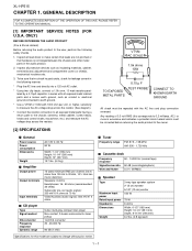
[1] IMPORTANT SERVICE NOTES (FOR U.S.A. To be corrected before returning the audio product to the owner.
[2] SPECIFICATIONS
I General
Power source Power consumption Dimensions
Weight...
Service Manual - Page 3
.... Illumination Light 14. Volume...or Fast Forward, Tape Fast Wind,
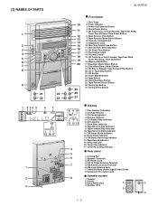
Tuner Preset Up, Time Up Button 16. CD Play or Repeat, Tape Forward... (Audio Signal) Input Jacks 8. [3] NAMES OF PARTS
1
2 3 4 5 6 7 8
9
21
23
22
24
1 2 34 5
67
14 15 16 17
1 2 3
XL-HP515
10... Extra Bass/Demo Mode Button 19. Sleep Indicator 16. FM Antenna Ground Terminal 6. Tweeter
2. Clock/Timer Button 5. CD ...
Service Manual - Page 4
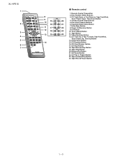
...Forward Play Button
24. CD Track Down or Fast Reverse, Tape Fast Wind,
Tuner Preset Down, Time Down Button
20
4. Extra Bass Button
22
8. CD Clear/Dimmer Button
17. Memory/Set Button
21.... Tape Reverse Play Button
19. CD Pause Button
22. Disc Direct Search Buttons
21
6. Power On/Stand-by Button
9. XL-HP515
1
2
3 4 5 6 7
8 9 10 15
16 11 17 12 18 13 19
14
I Remote control
1....
Service Manual - Page 5
...
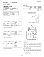
Frequency 10.7 MHz
Frequency Display
98 MHz
Setting/ Adjusting
Point
T302 (Turn the core of each disc can be performed under optimum conditions.
Input:...the VREF reference voltage is not needed when replacing the pickup. ADJUSTMENTS
XL-HP515
[1] ADJUSTMENT
1. CD SECTION
• Adjustment
Since this CD system ...time a disc is changed, these adjustments are performed automatically.
Service Manual - Page 6

...**'. 'ER-CD**' display will be displayed when error had been detected for 10 secs. XL-HP515
2) Tracking balance adjustment 3) Gain adjustment (The gain is compensated inside the IC so that... detect 'ON' level for the 5th times.
2 - 2 TRAY error. Can't detect CAM switch when CAM is moving . Can't detect TRAY switch when TRAY is moving . When it detect TRAY operation error during...
Service Manual - Page 7
... button. STOP
explanation:
a) Focus off set
= "FOF_XXXX"
b)Tracking off set
= "TOF_XXXX"
c)Tracking balance
= "TBAL_XX"
d)Tracking Gain
= "TGAN_XX"
f) Focus Gain
= "FGAN_XX"
g) RF level shift
= "RFLS_XX"
VOL - XL-HP515
2 - 3
Last memory
P.GEQ - then, press the CD
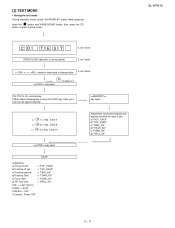
button to page 2-4
key input. CD T EST
OPEN/CLOSE operation is input into PLAY key, track number can...
Service Manual - Page 8
... be
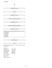
2 - 4
key input. Adjustment result automatically will display as below for each 2 sec : a) "FOF_XXXX" b) "TOF_XXXX" c) "TBAL_XX" d) "TGAN_XX" f) "FGAN_XX" g) "RFLS_XX"
key input. key input. key input.
XL-HP515
A
key input. Tracking OFF play from that specific point.
Tracking ON play at that specific point.
Service Manual - Page 9
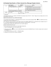
... referring to +B PROTECTION. ** is in hex valve.
+B PROTECTION is ready for the 5 th times. button and the X-BASS/DEMO button, press the ON/STAND-BY button. Press OPEN/CLOSE button... error is detected, 'CHECKING' will be display instead of Stereo System Error Message Display Contents
XL-HP515
CD TUNER
Error Contents
DISPLAY
Pickup Mechanism Error.
'ER-CD01'
CD Changer Mechanism Error. 'ER...
Service Manual - Page 10
... Roller Pawl
FF/REW Clutch
FF/REW Belt (C2)x1
Motor
Main Belt (C1)x1
Flywheel
Figure 3
Motor
(D1)x2 Ø2.6x5mm
Clutch Ass'y
3 - 1
Figure 4 XL-HP515
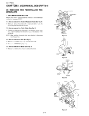
AXSMECeLuaHrdH-vrHkiAioPcePe5tP51M1T55aEnuRal3. How to remove the Belt (See Fig. 3)
1. MECHANICAL DESCRIPTION
[1] REMOVING AND REINSTALLING THE MAIN PARTS
1. How to the spring mounting position.
1.3. NOTE: When...
Service Manual - Page 11
... (A1) x 1 pc and gear (A2) x 1 pc. 2. Stop Washer (A1) x1
Optical Pickup
CD Mechanism
(A3) x2 ø2.6 x5mm
XL-HP515
Shaft Gear (A4) x1 (A2) x1
Figure 1
Reduction gear C
Front Rear Figure 2
Reduction gear D
Up
Down
Figure 3
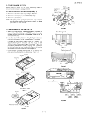
CD Disc
CD At '... 12 of it
with top plate. 2. Rotate reduction gear D clock-wise (Figure 3) to move the CD mechanism to protect the optical pickup from tray.
Service Manual - Page 12
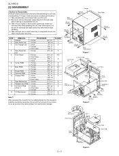
... 3. Socket F2) x1 1. Screw H1) x4 1. Socket N3) x1 1. Socket C2) x1 3. Screw J1) x1 1. Screw P1) x4 2. Flat Cable C3) x1 1. Screw G1) x2 2. XL-HP515
[2] DISASSEMBLY
Caution on static electricity of the unit. 2) Be sure to be
removed when disassembling the unit. After servicing the unit, be sure to rearrange...
Service Manual - Page 14
XL-HP515
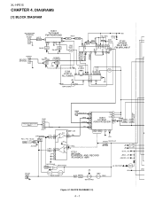
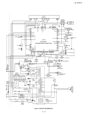
AXSMECeLuaHrdH-vrHkiAioPcePe5tP51M1T55aEnuRal4. DIAGRAMS
[1] BLOCK DIAGRAM
FM ANTENNA TERMINAL
SO302
B.P.F BF301
IC301 TA7358AP FM FRONT ...L VIDEO/AUX L 9
R
R 16
TAPE L 10
R 15
TUNER L 11
R 14
CD L 12
R 13
DI 1
CE 2
IC601 CLK 24
LC75341
21 R
AUDIO PROCESSOR 4 L
13
+B5
P.B 4 L PB
21 R
7 18 8 17 3 23 +B5
H/N 7 L REC 18 R
IC101 AN7345K PLAYBACK AND RECORD /PLAYBACK AMP. ...
Service Manual - Page 15
XL-HP515
SYSTEM MUTE VL+ VLñ GND
Q603 Q604
_+10V D_+8V
851
12
5 21
FL701 FL DISPLAY
28 31 32 41
+B10
44 45
MOTOR/ SOLENOID
DRIVER
Q701,702 Q712~715
TAPE MECHANISM
ASS'Y
+B10 LED701
38 48 69
78 79 VLOAD 36 P_IN 41 SMUTE 42 TIME LED
45 VOL_LED
AC_RLY...
Service Manual - Page 20
...page 6-1
1
2
3
4
5
6
Figure 6-2 SCHEMATIC DIAGRAM (1/10)
6 - 2
IC101 AN7345K XL-HP515
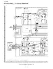
[3] WIRING SIDE OF PWB/SCHEMATIC DIAGRAM
MAIN PWB-A1(1/2)
FM SIGNAL
R601 1K
CD SIGNAL
R602 1K
C652... 220P C651 220P
A
AUX SIGNAL
IC601
PLAYBACK SIGNAL
LC75341
RECORD SIGNAL
AUDIO PROCESSOR
1 DI
CL
R605 C609
2 CE
VD
-+
-+ -+
-+
R613
10K 1/50
3 VSS
CCB...
Service Manual - Page 39
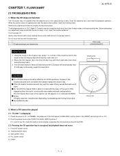
...not operate when the objective lens of isopropyl alcohol. Turn the power off any adjustment make certain that the lens... to the brush on IC1). 2) Does the pickup move to it contact with clean water and seek medical advice.... Remove the cabinet and follow the trouble shooting instructions. FLOWCHART
XL-HP515
[1] TROUBLESHOOTING
1. CD optical pickup Lens cleaner disc
Parts code ...
Service Manual - Page 48
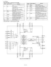
Data written into an internal latch in a timing of several 10µF to "L". Bass band filter comprising ... block for control.
Input selector output pin. Volume + equaliser output pin Treble band filter comprising capacitor and resistor connection pin. XL-HP515
IC601 VHiLC75341/-1: Audio Processor (LC75341)
Pin No. 1 2
3 4
5 6 7 8 9-12
Terminal Name DI CE
VSS LOUT
LBASS LTRE...
Service Manual - Page 52

...
REG3 VCC 13V
4 GND
1
REG4 5.1V
7
REG1 8.5V
Figure 5 BLOCK DIAGRAM OF IC
6
REG2 10.0V
8 - 10 XL-HP515
IC851 VHIAN80T53/-1: Multi Regulator (AN80T53)
Pin Terminal Name No.
REG1, REG2,REG3 and REG4 outputs are turned ON when this pin is 5V.
6 REG2 Output 7 REG1 Output
10V power supply with a minimum peak out...
Service Manual - Page 55
...;0.5%.)
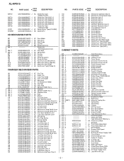
If there are no indications for other parts, the resistors are important for maintaining the safety and performance of the set . PARTS GUIDE
XL-HP515
MICRO COMPONENT SYSTEM
MODEL XL-HP515
XL-HP515 Micro Component System consisting of capacitors/resistors parts codes
Capacitors
VCC Ceramic type VCK Ceramic type VCT Semiconductor type VC • • MF Cylindrical type...
Service Manual - Page 60
...226 1 228 229
CCABA5762AW01 J
---- Tape Mechanism PWB Ass'y AZ Clutch Ass'y Block -- XL-HP515
NO.
GCOVA1364AWSA J
GCOVA1524AWSA J
GCOVA1531AWSA J
GCOVA1532AWSA J
GCOVAA054AWSA J
GDORF0117AWSA J
HBDGB1001AWSA J
HDECQ1111AWSA ... AD Holder,FL Display AB Cushion,Leg AV Heat Sink,Main AH Dust Sheet AE Edge Light Sheet AK Shield Sheet,Power PWB AF Shield Sheet,Main PWB AM AC Power Supply Cord...
Similar Questions

My Sharp Xl-dk255 Won't Turn On, But Timer Light Is Flashing.
(Posted by nancyrobinson 3 years ago)

Dial Flashing Blue Light
How do you stop the blue light on the dial from flashing constantly?
How do you stop the blue light on the dial from flashing constantly?
(Posted by b4rlpls 4 years ago)
Timer Light Flashing. It Turns Off When I Turn Up The Volume
sharp xl-dh229p it turns off when i turn up the volume. then a red timer light starts blinking
sharp xl-dh229p it turns off when i turn up the volume. then a red timer light starts blinking
(Posted by nickdeckerrrrr 10 years ago)

May I Download A Free Operating Manual For The Sharp Xp-hp515?
(Posted by jesso549 10 years ago)

Setting Sharp Stereo Shelf System Xl Hp515 Remote Control
Please help me set my remote control channels for my Hl hp515
Please help me set my remote control channels for my Hl hp515
(Posted by Cigarman8 11 years ago)