Sharp LC-26SH12U Support Question
Sharp LC-26SH12U Support Question
Find answers below for this question about Sharp LC-26SH12U - 26" LCD HDTV.Need a Sharp LC-26SH12U manual? We have 1 online manual for this item!
Question posted by paultewell on August 12th, 2010
The Sound Problem..
The problems vary, mine is whisper level volume no matter what the settings. Sometimes no volume when power on. On off cycle sometimes returns volume but never above whisper and no output from the D.O. to externals...
Current Answers
Related Sharp LC-26SH12U Manual Pages
Service Manual - Page 1

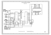
... VIEWS J-1~J-3 • REPLACEMENT PARTS LIST K1-1~K2-9
This document has been published to change without notice. S3701LC26SH12
LCD COLOR TELEVISION
MODEL LC-26SH12U
In the interests of user-safety (Required by safety regulations in some countries) the set should be restored to its original condition and only parts identical to those specified should be used .
Service Manual - Page 2

... end of the heat sink. A1-1 AVOID AN ELECTRIC SHOCK There is a high voltage part inside wiring is flowing.
3. The inside . BE CAREFUL WITH THE LCD PANEL
Avoid a shock to the IC and Transistor). Therefore, put in the original positions.
6. PERFORM A SAFETY CHECK AFTER SERVICING
Confirm that .
(INSULATION CHECK PROCEDURE)
1. MODEL...
Service Manual - Page 4

...Sound(FS) FP-FS
Left/Right Up/Down
Input Level Output Level S/N Ratio (Weighted) Horizontal Resolution at DVD Mode
RGB Signal Audio Signal
Output Level Input Level Output Level
at DVD at TV
Digital Output Level
S/N Ratio at DVD (Weighted)
Harmonic Distortion
Frequency Response :
at DVD
at Video CD
at SVCD
at CD
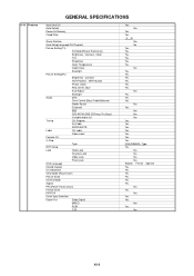
G-4 Power
Power Source
AC
DC
Power....7mmV
Color TFT LCD
1366(H) x 768...
Service Manual - Page 6
...Backlight
Picture Setting(PC)
Brightness , Contrast
HOR Position , VER Position
Phase, Clock
Red, Green, Blue
Auto Adjust
Backlight
Audio
MTS
Tone Control (Bass/Treble/Balance)
Stable Sound
Surround
BBE
...
CC Advanced
View Mode (Picture Size)
Picture Scroll
Cinema Mode
Aspect
PFC(Power Factor circuit)
Freeze frame
PIP/POP
Direct Input Selection
Digital Out
Dolby Digital...
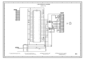
Service Manual - Page 15
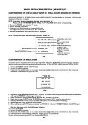
...power.
Set the VOLUME to minimum. 3. DOWN button on the screen.
ADDRESS DATA
HCS 00 00 HRM 0600 02 OEC6088A_T039 DTV CA03B72232
FIG. 2
4. When DATA is reached.
5. When satisfied correct DATA has been entered, turn off (return to STANDBY MODE) to finish DATA input. Set the VOLUME... on the set a factory...set and Channel button (1) on the POWER, and set...on the POWER, and set to the...
Service Manual - Page 19

... H POSI 60
22 V POSI 60
23 BAK LIGHT CENT
24 BAK LIGHT MAX
25 BAK LIGHT MIN
26 BRIGHT CENT
27 BRIGHT MAX
28 BRIGHT MIN
29 TINT
30 SHARP CENTER
31 SHARP MAX
32 SHARP MIN
... Confirmation of Fixed Value (Step No.)
Please check if the fixed values of each of the adjustment item is set correctly referring below. (AV/ANALOG TUNER/YUV/HDMI/PC/DIGITAL)
NO. Step No.
175
175
128
128
ADJ
...
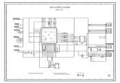
Service Manual - Page 26
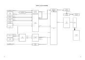
... COMPONENT: Y U V
DVI DATA 8~23 PC: R G B
DVI DATA 0~23
HDMI_I/F IC3601
SII9025CTU
DVI DATA 8~23 Y, Cb, Cr 16bit
TONE CTL IC IC1002
NJW1173V(TE1)
TONE AUDIO L/R
SOUND AMP IC IC1001
AN17808B
AMP L/R
SPEAKER L/R SP1001, SP1002
S0412F03
LVDS IC IC2405 ICSV385AGLFT
Tx OUT
CP2407 20389-Y30E...
Service Manual - Page 27

... POWR_ON_H
12 LIGHTE_CTL
13 INVERTER_H
14
AT +5V
15
16 POWER FAIL
17
18
GND
19
20 SW +4V 21 22 SW +1.5V 23
REG+9V IC3404 P.CON +9V BA00BC0WFP
SOUND AMP IC1001
AN17808B
AV SW IC701 AN15853B-E1
Q3410 LCD +B RSQ035P03
PANEL V2301 LK255T3LZ5A
Q3406 P.CON +5V 2SB1132
AD CONVERTER IC6601
MST3583M...
Service Manual - Page 35
... 35 34 33 32 31 30 29 28 27 26 25
HY27US08281A-TP
FLASH MEMORY IC
FOR FIRM UPDATE
CP2401.../TO MICON TX_[X242] RX_[X242]
FROM/TO SOUND I2C_DATA I2C_CLK
FROM/TO ASIC
4
DTV_RESET
FROM/TO ...# AD17
3.3 RDA AD16
0 CTSA# AE17
5V/3V LEVEL SHIFT
Q2402
D 5.0 2SK393800L
G
3.3 5.0 S
D
3.3
G
TDA 3.3 S 3.3
FWIRE_CSTA# JG2421
5V/3V LEVEL SHIFT Q2401
2SK393800L
RDA
FWIRE_RSTA# JG2422
R2437 4.7K
NC...
Service Manual - Page 36

... SCHEMATIC DIAGRAM
8
(DIGITAL PCB)
G
H
8
7
FROM/TO PC JACK PC/HDMI_H
6
FROM/TO INTERFACE_HDMI IC RXT0_RST
XRESET_HDMI
FROM/TO MICON
SD-H
5
AFT_1
AFT_2
AFT
FROM/TO SOUND DTUNER_AUDIO_SW
AUDIO_MUTE-H
4
FROM/TO AV SWITCH/JACK
SW_C_OUT
3
PC/HDMI_H
TU_VIDEO SIF
SW_Y/CVBS_OUT
FROM/TO POWER3
P.CON+5V
2
+2.5V_IO
+3.3V
GND
C2504 220P CH...
Service Manual - Page 37

...
C2581 68P CH
R2499 43K
0 6.0 6.0 6.0
4
3
2
1
+
+ -
5
6
7
8
5.9 6.0 6.0 9.0
R2498 43K
C2579 68P CH
C2584 10 C
B2430 FCM1608KF-151T06 C2585
10 C
W900 W901
P.CON+9V
C2586 0.001 B
7
6
5
FROM/TO SOUND 4
AUDIO_R_OUT AUDIO_L_OUT
3
C2557 10 C
C2558 10 C
C2587 0.001 B
2
NOTE: THIS SCHEMATIC DIAGRAM IS THE LATEST AT THE TIME
NOTE:THE DC VOLTAGE AT EACH PART...
Service Manual - Page 38

...127301123K2
1
SOUND+B
2
SOUND+B
3 SOUND GND
B3406 HCB3216KF-391T20
SOUND+B SOUND_GND
R3433 47
R3441 2.2K +-1%
4 SOUND GND
5.0
6
5
GND
6
GND
7
GND
8
SW+12V
9
SW+12V
10
LCD+B
11 SYS_POWER_H...Q3408 KRC102SRTK S802Y
4.7
4.7 4.7
4
5
6
S
D
D
LCD+B POWER_ON-H
LCD+B
LCD+B_SW IC Q3410
RSQ035P03
R3438 10K
15
AT+5V
16 POWER FAIL
5
17
GND
18
GND
19
GND
20
DTV+B2
...
Service Manual - Page 39
...220
V-S
B2502 FCM1608KF-151T06
R2507 180
B2503
FCM1608KF-151T06
B2504
FCM1608KF-151T06
CD7201 CHRU1301
LCD PANEL
V2301 LK255T3LZ5AZ
C2595 6.3V 220 V-S
NOTE:THE DC VOLTAGE AT EACH PART ...G
LVDS SHEMATIC DIAGRAM
(DIGITAL PCB)
C2591 0.1 B
C2593 0.1 B C2592 6.3V 220
V-S
C2594 0.1 B
3.3 Vcc
1
28 27 26 25 24 23 22 21 20 19 18 17 16 15 14 13 12 11 10 9
R7
2
3.3 TxIN5
R5
3
3.3 TxIN6
...
Service Manual - Page 41
...POWER3
DTV_ON-H LIGHT_CTL
LCD-H INVETER_H POWER_ON-H POWER_FAIL
P.CON+5V
4
FROM/TO SOUND
POWER_ON_MUTE_H
5.0 LCD_ON...
5.0 LCD_H
5.0 NC NC
0 NC NC
0 KEY_B
5.0 KEY_A
5.0 AFT
2.5 NC NC
0 REMOCON_IN
5.0
LED-H DTV_ON-H POWER_ON-H
C102 0.01 B
R104
100
33 32 31 30 29 28 27 26... IN 1
GND
2
AT+5V
3
STANDBY LED 4
POWER ON LED 5
3
D105 RB520S-30-TE61
R118 10K
...
Service Manual - Page 42

...
SW_Y/CVBS_OUT SW_C_OUT
4
PC/HDMI_H
SIF FROM/TO FLASH
I2C_CLK I2C_DATA
FROM/TO MICON C_SYNC
3
FROM/TO SOUND SW_A_OUT_L SW_A_OUT_R
FROM/TO PC JACK
2
VGA-R
VGA-G
VGA-B
DVI_A_IN_L
DVI_A_IN_R
FROM/TO POWER3 P.CON+5V ...151T06
BUFFER Q702
3.0
KTA1504S_Y_RTK 0
R718 470 R742 470
C725 1B 36 35 34 33 32 31 30 29 28 27 26 25 24 23 22 21 20 19
C721
0.01 B C722
0.01 B C723
0.01 B C724
0.01 B
AV ...
Service Manual - Page 43

...
KTC3875S_Y_RTK
R1002
5.0
1K 5.0
0
R1005 10K
R1001 4.3 MUTE SW
Q1001 1.5K KTC3875S_Y_RTK
4.2 3.0
0
R1003
5.0
1K 5.0
0
MUTE SW
Q1004
KTC3875S_Y_RTK
R1011 6.8K R1012 6.8K
C1009 0.0047 B
C1015 1B
SOUND AMP IC IC1001 AN17808B
+
ATT.
+
NC
CH1 IN
1
2
RIPPLE
FILTER RF
GND
CH2 IN
3
4
5
NC 0.2 16.0
0 0.2
+
+
-
- CAUTION:SINCE THESE PARTS MARKED BY ARE CRITICAL FOR...
Service Manual - Page 46

...+24V
GND
SW+12V[UNREG]
GND_S
SW+5.5V
SOUND+B[SW]
5
4
3
2
PCB240 CEF273
H
1
H-28
A
B
C
D
E
F
G
CHASSIS GND
POWER1 SCHEMATIC DIAGRAM
8
SH404
C436
1
YQ-36
(POWER PCB)
250V 0.0015 KX
6.3A 125V
CP413...1SS355
D435
R403
3
2
1
4.0 0 2.5
R451 C443
47 0.1 B
W828
R456 2.2K +-1%
SOUND+B[SW]
ERC91-02
1.8 3W
D413 1SS355
C419 100P CH D415 UDZS3.9B D423 1SS355 C421 0.022...
Service Manual - Page 47

...G
POWER2 SCHEMATIC DIAGRAM
8
(POWER PCB)
R478
7
FROM/TO POWER1
INV_SW+24V GND
SW+12V[UNREG]
GND_S
AT+5V
POWER_FAIL
P.CON+5V
SW+5.5V
GND
6
SOUND+B[SW]
R494 680 2W
R473...2
5.7 S
7
1.5 D
7313NH
SYS_POWER_H LIGHT_CTL LIGHT_POWER_H AT+5V
S802X S803X
S803Y
SW+12V 9
LCD+B
10
SYS_POWER_H 11
LIGHTE_CTL 12
LIGHT_POWER_H13
AT+5V
14
AT+5V
15
B402 HCB1608KF-181T20
B403 HCB1608KF...
Service Manual - Page 49

...
3
TX
4
RX
5
VDD
6
G
H
8
CP3401
CP411
CP406
SOUND+B 1
1
SOUND+B
+24V
1
SOUND+B 2
2
SOUND+B
+24V
2
SOUND GND 3
3 SOUND GND
+24V
3
SOUND GND 4
4 SOUND GND
+24V
4
GND
5
5
GND
+24V
5
GND
6
6...
22
DTV+B
DTV+B
23
23
DTV+B
POWER PCB PCB240
CEF273
DIGITAL PCB PCBDH0 CEF276
20...LCD PANEL CD7201
LCD PANEL V2301
E
21
GND
22
NC
23
GND
24
GND
25
GND
26...
Service Manual - Page 50

...
2ms 0.5V
2
10µs 0.5V
3
2ms 0.5V
4
2ms 0.5V
5
2ms 200mV
6
2ms 200mV
7
WAVEFORMS
2ms 200mV
8
1ms 200mV
15
2ms 200mV
9
MICON
50ns 500mV
16
SOUND
0.5ms 1.0V
10
VIDEO AD
10µs 100mV
17
50µs 1.0V
11
10µs 200mV
18
2ms 50mV
12
2ms 50mV
13
1ms 200mV...
Similar Questions


Sharp Tv Model Lc 22l50m-bk Key Function Problem.
I couldn't use keys either from remote or from TV model LC 22L50M , always switch to off and I need ...
I couldn't use keys either from remote or from TV model LC 22L50M , always switch to off and I need ...
(Posted by uswahengbam 8 years ago)

My Sharp Lc-26sh12u Will Not Work Through My Stero System On Channel 60.
I have hooked up my sharp T.v. to my Philips stero system through both the digital input and regular...
I have hooked up my sharp T.v. to my Philips stero system through both the digital input and regular...
(Posted by sailrv88 13 years ago)

The Sound And Channel Controlls Are Not Working On The Tv Itself. How Do I Fix?
I tried the settings and the remote. Nothing is turnning the tv up or down on the volumn or channel ...
I tried the settings and the remote. Nothing is turnning the tv up or down on the volumn or channel ...
(Posted by betterways01 13 years ago)

I Have A Sharp Lcd Lc-4067un With Red Power Light Blinking And No Sound And Pi
(Posted by default_11212124 14 years ago)