Sharp LC-26SH12U Support Question
Sharp LC-26SH12U Support Question
Find answers below for this question about Sharp LC-26SH12U - 26" LCD HDTV.Need a Sharp LC-26SH12U manual? We have 1 online manual for this item!
Question posted by pbelt2 on April 1st, 2012
No Picture
My TV loose picture periodically while maintaining sound. Today, it has no picture just black screen.
Current Answers
Related Sharp LC-26SH12U Manual Pages
Service Manual - Page 1

... ...I-1, I-2 • MECHANICAL EXPLODED VIEWS J-1~J-3 • REPLACEMENT PARTS LIST K1-1~K2-9
This document has been published to be used for after sales service only. S3701LC26SH12
LCD COLOR TELEVISION
MODEL LC-26SH12U
In the interests of user-safety (Required by safety regulations in some countries) the set should be restored to its original condition and only...
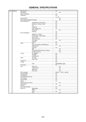
Service Manual - Page 4

... Tuner and Receive CH Intermediate Digital Frequency Analog
Preset CH Stereo/Dual TV Sound Tuner Sound Muting Video Signal
LCD Size / Visual Size LCD Type Number of Pixels
View Range
Position Size Impedance Max 10%(Typical) Analog Digital System Destination CH Coverage
Picture(FP) Sound(FS) FP-FS
Left/Right Up/Down
Input Level Output Level S/N Ratio...
Service Manual - Page 6
...(TV)
AV Mode(Picture Preference)
Brightness , Contrast , Color
Tint
Sharpness
Color Temperature
Cable Clear
Backlight
Picture Setting(PC)
Brightness , Contrast
HOR Position , VER Position
Phase, Clock
Red, Green, Blue
Auto Adjust
Backlight
Audio
MTS
Tone Control (Bass/Treble/Balance)
Stable Sound
Surround
BBE
SRS WOW (SRS 3D/Focus/Tru Bass)
Variable Audio Out
Tuning...
Service Manual - Page 16

...TV SIDE BAR
480I
Function
01 H POSI OSD 175
Step No. To display the adjustment screen for electrical adjustments.
1. FUNCTION 23 BAK LIGHT CENT 24 BAK LIGHT MAX 25 BAK LIGHT MIN 26...and press the channel button (34) on the remote control to select "CONTRAST MAX". 4. Check if the picture is normal. 12. Receive the monoscope pattern. (VIDEO Input) 7. Playback the DVD(480i) disc. (COMPONENT ...
Service Manual - Page 17

...144" 5. Press the INPUT button on the remote control until the screen begin to the COLORSTREAM HD mode. 14. Press the LEFT/RIGHT ...the adjustment mode display of Fig. 2-1 and
press the channel button (26) on the remote control to set to select "CONTRAST 40". 16. ...the brightness and contrast
to the HDMI mode. Check if the picture is normal. 6. becomes "132". 22. Press the LEFT...
Service Manual - Page 23

... circuit. Yes
Is there voltage at pins 7, Yes 8, 10, 11, 13, 14, 16, 17, 19 and 20 of CP2407 5V? Change IC2405.
TROUBLESHOOTING GUIDE
THE PICTURE DOES NOT APPEAR (1)
No Does backlight shine? Yes
Is there signal at pin No 28,29,30 and 31 of CD7201?
Check Q3410 and peripheral...
Service Manual - Page 24

E-4
Check IC701 and peripheral circuit. Check IC2401 and peripheral circuit. Yes
Yes Is there signal at pins A9 and A13 of IC701? Check IC2401 and peripheral circuit. TROUBLESHOOTING GUIDE
THE PICTURE DOES NOT APPEAR (2)
Is there signal at pins No 33 and 35 of IC2401? No
Check C2528, C2532 and peripheral circuit. No
Yes Is there signal at C2528 and C2532?
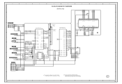
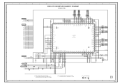
Service Manual - Page 33

... WITHOUT NOTICE
NOTE:THE DC VOLTAGE AT EACH PART WAS MEASURED WITH THE DIGITAL TESTER WHEN THE COLOR BROADCAST WAS RECEIVED IN GOOD CONDITION AND PICTURE IS NORMAL. B
C
D
E
F
G
H 8
ATSC/CLEAR CABLE ASIC IC IC2401 X242 (2/14 VSS)
7
0
0
D11 VSS_1
VSS_56 P9
0
0
D12 VSS_2
VSS_57 P10
0
0
D14 VSS_3
VSS_58 P11
0
0
D15 VSS_4...
Service Manual - Page 34

... PART WAS MEASURED
OF PRINTING AND SUBJECT TO CHANGE WITHOUT NOTICE
WITH THE DIGITAL TESTER WHEN THE COLOR BROADCAST
WAS RECEIVED IN GOOD CONDITION AND PICTURE IS NORMAL. A
B
C
H-3
D
E
F
G
H 8
7
6 5
4
3
2
PCBDH0 CEF276
H
1
H-4
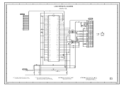
Service Manual - Page 35
...44 43 42 41 40 39 38 37 36 35 34 33 32 31 30 29 28 27 26 25
HY27US08281A-TP
FLASH MEMORY IC
FOR FIRM UPDATE
CP2401 YKF45-0036N
1
+5V
2
USBN
3
USBP.../TO AV SWITCH/JACK I2C_DATA I2C_CLK
5
FROM/TO MICON TX_[X242] RX_[X242]
FROM/TO SOUND I2C_DATA I2C_CLK
FROM/TO ASIC
4
DTV_RESET
FROM/TO VIDEO AD CONVERTER I2C_CLKC I2C_DATC
DVI_INT_ADC
FROM/TO POWER3...IN GOOD CONDITION AND PICTURE IS NORMAL.
Service Manual - Page 37

...-
5
6
7
8
5.9 6.0 6.0 9.0
R2498 43K
C2579 68P CH
C2584 10 C
B2430 FCM1608KF-151T06 C2585
10 C
W900 W901
P.CON+9V
C2586 0.001 B
7
6
5
FROM/TO SOUND 4
AUDIO_R_OUT AUDIO_L_OUT
3
C2557 10 C
C2558 10 C
C2587 0.001 B
2
NOTE: THIS SCHEMATIC DIAGRAM IS THE LATEST AT THE TIME
NOTE:THE DC VOLTAGE AT EACH PART... THE COLOR BROADCAST
1
WAS RECEIVED IN GOOD CONDITION AND PICTURE IS NORMAL.
Service Manual - Page 38

...CP3401(CP411) 127301123K2
1
SOUND+B
2
SOUND+B
3 SOUND GND
B3406 HCB3216KF-391T20
SOUND+B SOUND_GND
R3433 47
R3441 2.2K +-1%
4 SOUND GND
5.0
6
5
GND
6
GND
7
GND
8
SW+12V
9
SW+12V
10
LCD+B
11 SYS_POWER_H
12 ...THE DIGITAL TESTER WHEN THE COLOR BROADCAST WAS RECEIVED IN GOOD CONDITION AND PICTURE IS NORMAL. CAUTION:SINCE THESE PARTS MARKED BY CRITICAL FOR SAFETY,USE...
Service Manual - Page 39
...DIGITAL PCB)
C2591 0.1 B
C2593 0.1 B C2592 6.3V 220
V-S
C2594 0.1 B
3.3 Vcc
1
28 27 26 25 24 23 22 21 20 19 18 17 16 15 14 13 12 11 10 9
R7
2
3.3 TxIN5
...
R2507 180
B2503
FCM1608KF-151T06
B2504
FCM1608KF-151T06
CD7201 CHRU1301
LCD PANEL
V2301 LK255T3LZ5AZ
C2595 6.3V 220 V-S
NOTE:THE DC...COLOR BROADCAST WAS RECEIVED IN GOOD CONDITION AND PICTURE IS NORMAL. C
D
CAUTION:SINCE THESE...
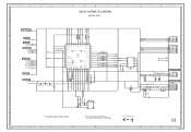
Service Manual - Page 40
... AVDD_PLL
1 2 3 4 5 6 7 8 9 10 11 12 13 14 15 16 17 18 19 20 21 22 23 24 25 26 27 28 29 30 31 32 33 34 35 36 37 38
1.0 2.5 2.5 3.3 0 0.7
0 1.3 1.0
0 0.7
00000000000000000 NC NC ... AT EACH PART WAS MEASURED WITH THE DIGITAL TESTER WHEN THE COLOR BROADCAST WAS RECEIVED IN GOOD CONDITION AND PICTURE IS NORMAL. C
D
NOTE: THIS SCHEMATIC DIAGRAM IS THE LATEST AT THE TIME OF PRINTING AND SUBJECT TO...
Service Manual - Page 41
... END AFT_1 AFT_2 SD-H AFT
5
FROM/TO POWER3
DTV_ON-H LIGHT_CTL
LCD-H INVETER_H POWER_ON-H POWER_FAIL
P.CON+5V
4
FROM/TO SOUND
POWER_ON_MUTE_H
5.0 LCD_ON
5.0 LCD_H
5.0 NC NC
0 NC NC
0 ...KEY_B
5.0 KEY_A
5.0 AFT
2.5 NC NC
0 REMOCON_IN
5.0
LED-H DTV_ON-H POWER_ON-H
C102 0.01 B
R104
100
33 32 31 30 29 28 27 26...PICTURE IS NORMAL.
Service Manual - Page 42

.../CVBS_OUT SW_C_OUT
4
PC/HDMI_H
SIF FROM/TO FLASH
I2C_CLK I2C_DATA
FROM/TO MICON C_SYNC
3
FROM/TO SOUND SW_A_OUT_L SW_A_OUT_R
FROM/TO PC JACK
2
VGA-R
VGA-G
VGA-B
DVI_A_IN_L
DVI_A_IN_R
FROM/TO POWER3 P.CON+...BUFFER Q702
3.0
KTA1504S_Y_RTK 0
R718 470 R742 470
C725 1B 36 35 34 33 32 31 30 29 28 27 26 25 24 23 22 21 20 19
C721
0.01 B C722
0.01 B C723
0.01 B C724
0.01 B
...PICTURE IS NORMAL.
Service Manual - Page 44

... C3654
HDMI_+1.8V
GND
C3616 0.1 B
6
0 1.8 3.2 0 3.1 3.1 0 0 3.3 3.3 3.3 0 01.8 1.8 0
3.3 0
3.3 03.3 3.3 3.3
DVIDE
C3604 10 C
36 35 34 33 32 31 30 29 28 27 26 25 24 23 22 21 20 19 18 17 16 15 14 13 12 11 10 9 8 7 6 5 4 3 2 1
R0PWR5V R1PWR5V
DSCL0 DSDA0 DSCL1 DSDA1
CSCL CSDA OVCC...
WITH THE DIGITAL TESTER WHEN THE COLOR BROADCAST
WAS RECEIVED IN GOOD CONDITION AND PICTURE IS NORMAL.
Service Manual - Page 45

... 22P CH
NOTE:THE DC VOLTAGE AT EACH PART WAS MEASURED WITH THE DIGITAL TESTER WHEN THE COLOR BROADCAST WAS RECEIVED IN GOOD CONDITION AND PICTURE IS NORMAL.
NOTE: THIS SCHEMATIC DIAGRAM IS THE LATEST AT THE TIME OF PRINTING AND SUBJECT TO CHANGE WITHOUT NOTICE
B
C
D
E
F
FROM/TO AV SWITCH JACK...
Service Manual - Page 47

...THE COLOR BROADCAST WAS RECEIVED IN GOOD CONDITION AND PICTURE IS NORMAL.
A
B
C
D
E
F
...
13.5
12.4 5.1
0 R499 2.5 0
SOUND+B[SW]
SOUND+B 1
P.CON+5V
R495
12.8
5.1
5.2
100 R483
R484
GND_S
SOUND+B 2 SOUND GND 3
C461 6.3V 1000 ZL_P
C453 16V1000... LIGHT_CTL LIGHT_POWER_H AT+5V
S802X S803X
S803Y
SW+12V 9
LCD+B
10
SYS_POWER_H 11
LIGHTE_CTL 12
LIGHT_POWER_H13
AT+5V
14
AT...
Service Manual - Page 49

...CP102
GND
1
RESET
2
TEST
3
TX
4
RX
5
VDD
6
G
H
8
CP3401
CP411
CP406
SOUND+B 1
1
SOUND+B
+24V
1
SOUND+B 2
2
SOUND+B
+24V
2
SOUND GND 3
3 SOUND GND
+24V
3
SOUND GND 4
4 SOUND GND
+24V
4
GND
5
5
GND
+24V
5
GND
6
6
GND
GND
6
GND
7
... PIECES
C
D
TO LCD PANEL CD7201
LCD PANEL V2301
E
21
GND
22
NC
23
GND
24
GND
25
GND
26
GND
27
GND
28 ...
Similar Questions


My Sharp Aquos Lc C4067un Tv Stopped Working No Power How Can I Fix This?.
(Posted by BFGOLDSTON43 9 years ago)

My Sharp Lc-26sh12u Will Not Work Through My Stero System On Channel 60.
I have hooked up my sharp T.v. to my Philips stero system through both the digital input and regular...
I have hooked up my sharp T.v. to my Philips stero system through both the digital input and regular...
(Posted by sailrv88 13 years ago)