Sharp LC-26SB14U Support Question
Sharp LC-26SB14U Support Question
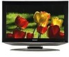
Find answers below for this question about Sharp LC-26SB14U - 26" LCD TV.Need a Sharp LC-26SB14U manual? We have 1 online manual for this item!
Question posted by jaimeleeann on October 18th, 2010
How Do I Get The Captions Off If I Lost The Controller?
The person who posted this question about this Sharp product did not include a detailed explanation. Please use the "Request More Information" button to the right if more details would help you to answer this question.
Current Answers
Related Sharp LC-26SB14U Manual Pages
Service Manual - Page 1
...-6
Parts marked with specified ones for maintaining the safety and performance of the set . " are subject to change without notice.
SERVICE MANUAL
No.S480ILC26SB14
LCD COLOR TELEVISION
MODEL LC-26SB14U
In the interests of user-safety (Required by safety regulations in some countries) the set should be restored to its original condition and only...
Service Manual - Page 2
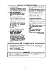
... MANUAL. Therefore, the part which are assembled in the original positions.
6. BE CAREFUL WITH THE LCD PANEL
Avoid a shock to the important parts for safety, or which is replaced should be found on ...the cabinet, chassis and parts. Remove the antenna terminal on TV and turn
on the contact section of the heat sink. PART NO. Avoid an electric shock...
Service Manual - Page 3
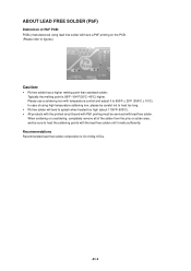
... to splash when heated too high (about 1100oF/ 600oC). • All products with the printed circuit board with PbF printing must be serviced with temperature control and adjust it melts sufficiently. Typically the melting point is Sn-3.0Ag-0.5Cu.
Service Manual - Page 4
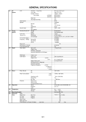
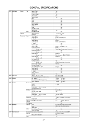
GENERAL SPECIFICATIONS
G-1 TV System
G-2 Tuning System
G-3 Signal
LCD
LCD Size / Visual Size
LCD Type
Number of Pixels
View Range
Left/Right
Up/...CH
Destination
CH Coverage
Intermediate Digital
Frequency Analog Picture(FP)
Sound(FS)
FP-FS
Preset CH
Stereo/Dual TV Sound
Tuner Sound Muting
Video Signal
Input Level
Output Level
S/N Ratio (Weighted)
Horizontal Resolution at DVD ...
Service Manual - Page 5
G-9 Remote Control
GENERAL SPECIFICATIONS
Unit
Glow in Dark Remocon
Remocon Format
Format
Custom Code
Power Source
Voltage(D.C)
UM size x pcs
Total Keys
Keys
POWER
FUNCTION
Source POWER
...
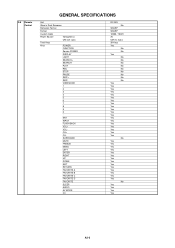
Service Manual - Page 6
...Filter
Game Position
Auto Setup(Language/CH Program)
Picture Setting(TV)
AV Mode(Picture Preference)
Brightness , Contrast , Color
Tint...Phase, Clock
Red, Green, Blue
Auto Adjust
Audio
MTS
Tone Control (Bass/Treble/Balance)
Stable Sound
Surround
BBE
SRS WOW (...
Lock
Hotel Lock
Channel Lock
Video Lock
Panel Lock
Menu Language
Closed Caption
CC Advanced
View Mode (Picture Size)
...
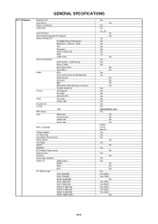
Service Manual - Page 7
...;1080i
Wall Mount
Size W x H(mm)
Screw Size
Owner's Manual
Language
w/Guarantee Card
Remote Control Unit
Rod Antenna
Poles
Terminal
Loop Antenna
Terminal
U/V Mixer
DC Car Cord (Center+)
Guarantee Card
Warning... size x pcs
OEM Brand
AC Adapter
AC Cord (for AC Adapter)
AC Cord (Flat Polarity Plugs)
Cable Cramp
Stand
Stand Screw
Hexagon Wrench
AV Cord (2Pin-1Pin)
Registration ...
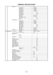
Service Manual - Page 8
...
Eject
Skip+, Search+
Skip-, Search- No
Yes
Green procurement of Origin
Drop Test
Height (cm)
Container Stuffing (40' container)
w/Pallet
w/Wrapping
Cabinet Front
Rear
Jack Panel
PCB
Non-Halogen Demand
Eyelet Demand
Environmental standard requirement
Pb-free
Measures for Whisker
Rohs
Yes
Yes
Yes
Yes
Yes
No
No
No
No
No...
Service Manual - Page 9
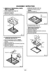
... 14 screws (1). 2. Remove the Operation PCB in the direction of arrow (A).
(1) (1) Remocon PCB
(A)
Fig. 1-3
Back Cabinet
1-4 LCD BLOCK (Refer to Fig. 1-2)
1. DISASSEMBLY INSTRUCTIONS
1. Remove the 7 screws (2). 3. Remove the 7 screws (3). 7. Remove the Holder Panel. 3. REMOVAL OF MECHANICAL PARTS AND P.C. Remove the Back Cabinet in the direction of
arrow (A). 3. Disconnect the following...
Service Manual - Page 10
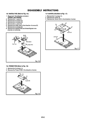
... INSTRUCTIONS
1-5: DIGITAL PCB (Refer to Fig. 1-7)
1. Remove the 1 screw (1). 3. Remove the 4 screws (1). 2. Remove the 5 screws (1). 2. Remove the Cover LCD in the direction of arrow.
(2)
(1) (1)
(1) (1)
Cover LCD
LCD Panel
(B)
Fig. 1-7
Fig. 1-6
1-6: POWER PCB (Refer to Fig. 1-6)
1. Remove the 1 screw (4). 6. Remove the 5 screws (5). 8. Remove the 3 screws (3). 5. Remove...
Service Manual - Page 11
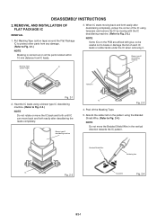
... pickup the corner of each IC leads or solder lands under the IC when removing it. REMOVAL AND INSTALLATION OF FLAT PACKAGE IC
REMOVAL
1. Absorb the solder left on the pattern using tweezers and remove the IC by moving with glue,... Wire
Soldering Iron
IC
Fig. 2-2
IC pattern
Fig. 2-4
B2-1 Put Masking Tape (cotton tape) around the Flat Package IC to protect other parts from IC leads.
3.
Service Manual - Page 13
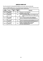
..."WHEN REPLACING EEPROM (MEMORY) IC".
Check of the SUM DATA and MICON VERSION on the screen.
Releasing of factory TV data. Power ON
VOL.
DOWN (Minimum)
6
2 sec. Refer to the "WHEN REPLACING EEPROM (MEMORY) IC".... press and hold both buttons simultaneously on the main unit and on the remote control for more than a the standard time in the appropriate condition. (See below chart...
Service Manual - Page 14
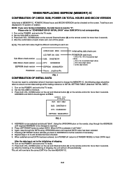
...Sub Micon check version Main Micon check version
EEPROM check version Parameter
CHECK SUM: 3ED6 LCD PWR ON: 0000 SUB: DA0E782141 DTV: CA09E83052 EEPROM: W34N02PE01 Picture: _dispSmartPic
Initial ...has been entered, turn off the power. After the data input, set to the TV mode. 11. Turn on the remote control for more than 2 seconds. 12. After the finishing of the initializing of shipping, ...
Service Manual - Page 15
...Fig. 12.
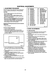
4. Use the UP/DOWN button or Channel button (0-9) on the remote control to select "R DRIVE(N)". 6.
D-1 ADJUSTMENT PROCEDURE
Read and perform these adjustments when repairing ...cause damages to minimum. 2.
ELECTRICAL ADJUSTMENTS
1. TV s.stretch 480i
Function
03 R DRIVE (N)
8
Step No. Adjust the LEFT/RIGHT button on the remote control to
the AV mode. 4. Place the ...
Service Manual - Page 16
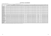
... of Fixed Value (Step No.) Please check if the fixed values of each of the set correctly referring below. (TV/AV/COMPONENT/HDMI/PC/DTV)
NO. FUNCTION
AV
COMPONENT
HDMI
PC
TV
GAME
CVBS Y/C
480i/576i 480p/576p 720p 1080i 480i/576i 480p/576p 720p 1080i VGA 640x480 1280x720 640*480 720...
Service Manual - Page 20
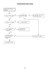
No
Change DIGITAL PCB.
Is there voltage at pins 13, Yes 14, 16, 17, 19, 20, 22, 23, 25 and 26 of CP2804?
Check IC401, T401, D437 and peripheral circuit. E-3
Change V2301 (PANEL). Check IC407 and peripheral circuit. Yes
Connected CD2804.
Yes
Is there signal at pins 1, No 2, 3, 4 and 5 of CP2804 5V?
Yes...
Service Manual - Page 33
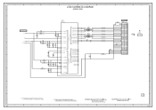
.../GND 29
GND
28
LVDS0OUT0M E19 1.5 LVDS0OUT0P F19 1.5
NR2811 CRA108220JV
LCD_TXOUT0LCD_TXOUT0+
GND
27
RXIN0- 26
RXIN0+ 25
FROM REGULATOR2
B2806
HCB1608KF-221T20
D3.3V
B2807
HCB1608KF-221T20
6
C2865 10V 22 V-S... 23
RXIN1+ 22
GND
21
RXIN2- 20
CD2804
V2301_1 V260B1-L01_M
RXIN2+ 19
CURU1704
LCD PANEL
6
GND
18
RXCLK IN- 17
RXCLK IN+ 16
PLL POWER LVDS_CH0
D1.0V VDD_PANEL
...
Service Manual - Page 41
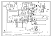
... P_GND
SOUND+B SOUND_GND
5
D405
R412 B404
R429 1M 1/4W RCR C423
T401 81400854
B401
1.0
0 6.0
D416 31DQ06-FC
1N5406FL-6737
POWER CONTROL IC
0.22 1W
W5RH3.5X5X1.0
630V 0.082 FGSM
W5RH3.5X5X1.0
8
9
C424_1 2KV 220P
R
W840
P_GND
FROM/TO REGULATOR
5
IC401
...CRITICAL FOR SAFETY,USE ONES DESCRIBED IN PARTS LIST ONLY
CAUTION: DIGITAL TRANSISTOR
F
G
2
PCB240 CEG353
1
H
H-26
Service Manual - Page 49
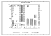
...GND
18
RXIN2+
19
RXIN2-
20
GND
21
RXIN1+
22
RXIN1-
23
GND
24
RXIN0+
25
RXIN0-
26
GND
27
GND
28
VDD+3.3V/NC/GND 29 NC VDD+3.3V/NC/GND 30
SUB MICON CP6201
GND 1... TRST_N 2 TDO 3 ASEBRKAK_N 4 TMS 5 TDI 6 RESET_N 7 FLASH_WP 8 ASEMD0 9 GND 10 VDD33 11 GND 12
CD2804
V2301_1 LCD PANEL
24
DIGITAL PCB PCBDH0 CEG352
SIF-out 5
AGC 7 NC V_OUT 8
+5V 9
TU 11 NC +30V 12
IF_OUT 18 NC...
Service Manual - Page 55
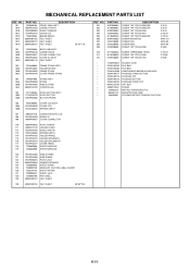
...'Y COVER LCD SPRING EARTH
107
8965TS1210 CUSHION W10/H12/L10
108
761WSA0459 SHIELD IC
109
706WPA0027 COVER CONNECTOR
110
706WPA0033 PLATE POWER
111
899RFC21V0 HOLDER CORD
112
752WSA0705 SHIELD DIGITAL
113
753WUA0063 SPRING EARTH
114
761WPAA183 HOLDER PANEL
115
761WPA0473 HOLDER SPEAKER-L
116
761WPA0474 HOLDER SPEAKER-R
117
761WPA0477 COVER HINGE
118
723000D908...
Similar Questions

How To Fix A Sharp Lcd Tv Wont Power On Model Lc 26sb14u
(Posted by lilKo 9 years ago)

White Screen Problem With Lcd Tv Lc26sb14u
How to troubleshoot and repair ?
How to troubleshoot and repair ?
(Posted by thl748 11 years ago)

Sharp 26' Lcd Lc-26sb24u
I have a shrp 26" LCD tv model LC-26SB24U the the green light will come on for about 15-20 sec. then...
I have a shrp 26" LCD tv model LC-26SB24U the the green light will come on for about 15-20 sec. then...
(Posted by awoliver86 12 years ago)

Lcd Tv -- Lamp
Does the sharp LC42SB45UT LCD TV contain a lamp?The Sharp warranty will not cover a tech to come out...
Does the sharp LC42SB45UT LCD TV contain a lamp?The Sharp warranty will not cover a tech to come out...
(Posted by kles 12 years ago)

Sharp Lc-26sb14u Closed Caption
Help Needed, Sharp LC-26SB14U Closed Caption will not work with COMCAST Cable.
Help Needed, Sharp LC-26SB14U Closed Caption will not work with COMCAST Cable.
(Posted by connieusa 13 years ago)