
Pioneer PRO-507PU Support Question
Pioneer PRO-507PU Support Question
Find answers below for this question about Pioneer PRO-507PU.Need a Pioneer PRO-507PU manual? We have 1 online manual for this item!
Question posted by franciscosalazar1821 on July 18th, 2022
Hiw To Either Reprogramate Or Exchange Cable Card
The person who posted this question about this Pioneer product did not include a detailed explanation. Please use the "Request More Information" button to the right if more details would help you to answer this question.
Current Answers
Answer #1: Posted by SonuKumar on July 18th, 2022 8:10 AM
SonuKumar

Member since:
May 9th, 2021 Points: 16,609,790

Member since:
May 9th, 2021 Points: 16,609,790
https://www.amazon.com/HQRP-PRO-505PU-PRO506PU-PRO-506PU-PRO-507PU/dp/B00L48VR68
https://www.ebay.com/itm/283781907301
https://www.pioneerelectronics.com/PUSA/Home/Plasma/PDP-5070HD
Please respond to my effort to provide you with the best possible solution by using the "Acceptable Solution" and/or the "Helpful" buttons when the answer has proven to be helpful.
Regards,
Sonu
Your search handyman for all e-support needs!!
Answer #2: Posted by Technoprince123 on July 18th, 2022 8:48 AM
Technoprince123

Member since:
February 8th, 2021 Points: 1,205,190
Member since:
February 8th, 2021 Points: 1,205,190
https://www.manualslib.com/products/Pioneer-Pro-507pu-155137.html
https://manualzz.com/doc/23060006/pioneer-pro-507pu-service-manual
Please response if this answer is acceptable and solw your problem thanks
Related Pioneer PRO-507PU Manual Pages
Service Manual - Page 1
... INFORMATION etc. ARP3355
SCHEMATIC DIAGRAM and PCB CONNECTION DIAGRAM
CONTENTS
1. Model
Type
Power Requirement
Remarks
PRO-507PU
KUCXC
AC120 V
¶ This service manual should be used together with the following manual(s):
...2.8 HN MODULE ASSY (5/6 24 2.9 HN MODULE ASSY (6/6 26 3.
ARP3399
PLASMA DISPLAY
PRO-507PU
THIS MANUAL IS APPLICABLE TO THE FOLLOWING MODEL(S) AND TYPE(S).
Service Manual - Page 2
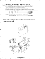
...effective digits (such as shown in this manual. 1.1 PACKING SECTION
B 18
17
22
C
6
4
3
Noise filter for antenna cable
13
9, 11, 14
Binder for the base model. CONTRAST OF MISCELLANEOUS PARTS
NOTES: Parts marked by J=5%,
and K=10%).
560...
Bead band x3
10 20 12
19 15 D
21
2
PRO-507PU
1
2
3
4
indicate the pages and Nos. in our Master Spare Parts List. 1
2
3
4
1.
Service Manual - Page 4
... Assy 2..P. Mark
Symbol and Description
Part No. No. 1
2
3
4
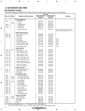
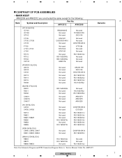
1.2 EXTERIOR SECTION
CONTRAST TABLE
PRO-507PU/KUCXC and PDP-5071PU/KUCXC are constructed the same except for the following :
A Ref. Chassis (507E)... Wire (J124)
Not used
ADX3417
No.4
3P Housing Wire (J125)
Not used
ADX3484
No.5
Flexible Cable (J216)
Not used
ADD1474
No.6
P13 - 17 P13 - 22 P13 - 22
NSP
REAR SECTION...
Service Manual - Page 6
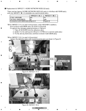
... (4th pin in IC7803) on a service parts ass'y 3. Fix the wire by bond-lock.
4th pin in IC7803
C
Figure A: AWV2311-A /J
ADX3484
M17
D CN7802
Figure B: AWV2311-B /J
6
PRO-507PU
1
2
3
4 1
2
3
4
Replacement of AWV2311: HOME NETWORK MODULE ass'y
There are two types of HOME NETWORK MODULE ass'y in interface with MAIN ass'y,
and only AWV2311-B /J is...
Service Manual - Page 7
ARP3355"
Remarks
PRO-507PU
5
6
7
8
A B C D 7 AWV2312
AWV2309
[DT AV BLOCK] IC7105 IC7108 Q7102
R5520H001B Not used Not used
Not used TC7WH157FU
2SC4116
C7135 C7136, C7138 C7178
ACH1421 CKSSYB104K10
Not used
...
Service Manual - Page 8
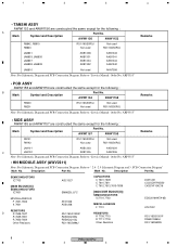
... DDR BLOCK(U)] SEMICONDUCTORS
IC7701,7702
MISCELLANEOUS F 7701
RESISTORS R 7709,7710 R 7711-7718 Other Resistors
DCH1201 CCSSCH7R0D50 CKSSYF104Z16
EDD2516AKTA-6B
ATL7002
RS1/16SS1001F RAB4CQ560J RS1/16SS###J
8
PRO-507PU
1
2
3
4 Refer to "Service Manual: Order No.
ARP3355"
• HN MODULE ASSY (AWV2311)
Note: For Schematic Diagram and PCB Connection Diagram. Description
Part No...
Service Manual - Page 10
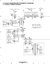
BLOCK DIAGRAM AND SCHEMATIC DIAGRAM
2.1 OVERALL WIRING DIAGRAM
A
B
C
D 10 1
AWV2313- (REGULAR) AWW1156
AWV2310- (ELITE) AWW1153
(REGULAR) AWV2313AWW1157
(ELITE) AWV2310AWW1155
PRO-507PU
2
3
4 1
2
3
4
2.
Service Manual - Page 12
IC]
IC7902 NJM2846DL3-25
[Regulator IC]
IC7904 LTC3412EFE [SW Reg. IC]
IC7901 LM2664M6X [Converter IC]
12
PRO-507PU
1
2
3
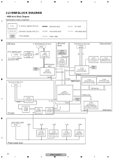
4 Ethernet block
+5V for Power supply
CN7901
+5.0V
D Power supply block
+3.3V
+2.5V
+1.2V
-5.0V
IC7903 LTC3412EFE [SW Reg. mode filter]
B
directly to USB Receptacle ...
Service Manual - Page 13
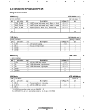
USB cable
voltage (V)
+5.0
+3.3 / 0
+3.3 / 0
0
C
0
HNM Ass'y
[HN7] CN7802*
pin
pin name
1 N.C.
2 +5.1V
3 N.C.
MTB MAIN Ass'y
[M15] ...wire is directly soldered to 4th pin of IC78.03
MTB MAIN Ass'y
CN4011
voltage (V)
pin
-
1
+5.1
2
-
3
D
PRO-507PU
13
5
6
7
8 5
6
7
8
2.3 CONNECTOR PIN DESCRIPTION
• Voltage at each connecter. I /O USB differential signal...
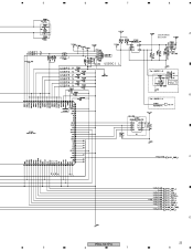
Service Manual - Page 23
5
6
7
8
A
USB POWER SECTION
B
C
D
PRO-507PU
23
5
6
7
8
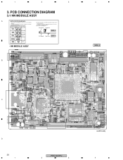
Service Manual - Page 28
..., be sure to check with resistor
DGS
D G SD G S
Field effect transistor
P.C.Board Chip Part SIDE B
Resistor array
3-terminal regulator
• HN MODULE ASSY
B
4 SIDE A
C
D
28 1
PRO-507PU
2
3
(ANP2148B) 4 Part numbers in PCB diagrams match those in the schematic diagrams.
2. Symbol In PCB Diagrams
Symbol In Schematic Diagrams B C EB C E
Part Name
3. PCB CONNECTION...
Service Manual - Page 30
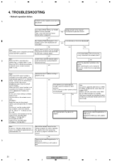
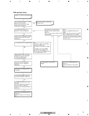
...the network client? Replace the HNM ass'y with a network cable? 1
2
3
4
4. yes
Jump and refer to... and correctly inserted into both
network hub, a straight cable is properly set an appropriate IP address by the Subnet...Try WMV, except that a correct network cable is
B
When the PDP is connected to...network server, a cross (reverse)
yes
cable is the network server name displayed and ...
Service Manual - Page 31
...played though it can be displayed!
There may be selected, try a multi card reader instead of 720p resolution are not supported by this . D
PRO-507PU
31
5
6
7
8 Refer to CN4011 in HNM ass'y? yes
Is...
The failed contents may be something defective in the device displayed?
C
Is the inside USB cable is used as a USB device, try other end is attached to the sheet of the ...
Service Manual - Page 32
...
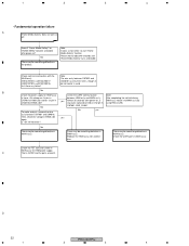
B
Check the power supply for about 40 seconds until "Home Media Gallery" turns selectable.
Check the FET transistor switch in
between CN7901 and CN4016. D
32
PRO-507PU
1
2
3
4 Check each wire connection with another one. Check the UART communication
Note:
Is there +5V voltage on , is
HNM ass'y notice it . Then, check the...
Service Manual - Page 33
5
6
7
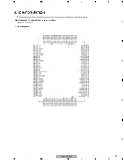
5. IC INFORMATION
• The information shown in the list is basic information and may not correspond exactly to that shown in the schematic diagrams.
RTL8100CL-LF (HN MODULE Assy: IC7754)
• Ethernet Controller IC
Pin Arrangement
8 A
B
C
D
PRO-507PU
33
5
6
7
8
Similar Questions

Elite Pro-507 Pu Plasma Tv By Pioneer Needs Repair Here Is My Email.
Thanks.
Thanks.
(Posted by samsonomoregie 6 years ago)

Cablecard With Pioneer Elite 507pu
Can I use a cable card with this tv or do in need a box ?
Can I use a cable card with this tv or do in need a box ?
(Posted by Ritalowes 9 years ago)
Pioneer Elite Plasma Tv Pro-ro4u No Signal With Satellite Conection
(Posted by jadgjust4u 10 years ago)

Elite Pro -506 Pu Operating Instructions
Where can I down the manual operating instructions for Elite Pio neer PRO-506PU
Where can I down the manual operating instructions for Elite Pio neer PRO-506PU
(Posted by meket3 10 years ago)

Cables For Pioneer Pdp-4360hd Plasma Display System
RE: PioneerPDP-4360HD Plasma Display System I recently relocated to Vancouver, during the move I lo...
RE: PioneerPDP-4360HD Plasma Display System I recently relocated to Vancouver, during the move I lo...
(Posted by rahimlavji 11 years ago)