
LiftMaster LA400 Support Question
LiftMaster LA400 Support Question
Find answers below for this question about LiftMaster LA400.Need a LiftMaster LA400 manual? We have 3 online manuals for this item!
Question posted by albeech56 on March 25th, 2014
How To Connect A Gatemate Free Exit 5 Wire System To A La400s
What connections do you use on the control board?
Current Answers
Related LiftMaster LA400 Manual Pages
LA400 Manual - Page 2

...Gate Post Secure Gate Bracket to Gate Warning Sign Placement Standard Control Box Large Metal Control Box (XLM)
WIRING
Connect the Gate Operator (Gate 1) to the Control Box Set the Bipart Delay (Model LA400-S Only) Connect the Gate Operator (Gate 2) to the Control Box (Model LA400-S Only) Junction Box (Model LA400-S Only) Connect Transformer to Control Board Earth Ground Rod Installation (Optional...
LA400 Manual - Page 6

... in fire. Upon completion of entrapment or obstruction exists. Operator MUST be properly grounded and connected in separate conduit.
• BEFORE installing power wiring or control stations be enclosed in BOTH the open and close gate. • NEVER use force adjustments to run in accordance with proper weatherproof fixtures. To AVOID damaging plug-in transformer...
LA400 Manual - Page 19

....
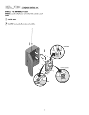
1 Remove screws and open the control box.
1
2 Disconnect the reset button, alarm, and coaxial connector.
3 Loosen screws to remove the control board and mounting bracket.
4 Remove the control board.
5 Remove batteries and set aside.
6 Select mounting holes and knock out using a screwdriver and hammer.
7 Secure the control box to mounting surface using the appropriate hardware (not...
LA400 Manual - Page 20
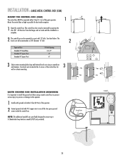
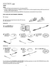
INSTALLATION » STANDARD CONTROL BOX
INSTALL THE CONTROL BOARD
NOTE: Make sure the battery leads are on the left side of the control box and not pinched.
1 Attach the antenna. 2 Reinstall the batteries, control board, alarm and reset button.
1 2
Coaxial Connector
Reset Button Connections Alarm
19
LA400 Manual - Page 21
... PWR
AC PWR /SOLAR
LOOP INPUTS
20 The control box door may be mounted to a post with #12 copper wire to one of the two green ground screws inside the control box. Use knock outs located at the 4 corners of the control box for best radio reception.
1
Open the control box. NOTE: The additional standoffs are specifically designed...
LA400 Manual - Page 22

...: There are two receptacles located inside the control box. The illustrations show the standard control box, not the XLM control box.
21 One of the control box based on the application requirements.
2 Depending on the voltage and application the 120 Vac access panel may be used to access the wiring.
3 Connect two 7AH batteries, purchased separately.
ALARM...
LA400 Manual - Page 24

... the control board. BIPART DELAY
BI-PART DELAY
Z9
Z8
OFF
MAX
OUTSIDE PROPERTY
Primary Gate - WIRING » SET THE BIPART DELAY (MODEL LA400-S ONLY)
SET THE BIPART DELAY (MODEL LA400-S ONLY)
In some dual gate installations, one gate or if using a
solenoid lock, for the control box, then mount the control box on the opposite side, but connect...
LA400 Manual - Page 25

... conduit at least 18" (45.7 cm) below ground level (grade)
Terminal blocks can be used for the extension cable.
WIRING » CONNECT THE GATE OPERATOR (GATE 2) TO THE CONTROL BOX (MODEL LA400-S ONLY)
CONNECT THE GATE OPERATOR (GATE 2) TO THE CONTROL BOX (MODEL LA400-S ONLY) Before digging, contact local underground utility locating companies.
1 Trench across driveway to be...
LA400 Manual - Page 28
...
Refer.
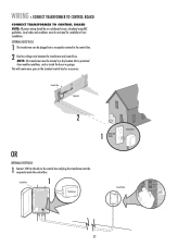
Eug. NOTE: The transformer must be located in the standard control box for suitability of wire installation. WIRING » CONNECT TRANSFORMER TO CONTROL BOARD
CONNECT TRANSFORMER TO CONTROL BOARD
NOTE: All power wiring should be plugged into a receptacle external to the control box and plug the transformer into the receptacle inside the house or garage. Manu. 1 Rm Main Dept.
LA400 Manual - Page 29
...
The batteries are charged in circuit using the transformer (provided). The 24 Vac input can accept a charging transformer (26 Vac, 29 VA or 36 Vdc, 40 VA).
1 Connect the plugs from the batteries to the screw terminal of the control board marked . WIRING » EARTH GROUND ROD INSTALLATION (OPTIONAL) + CONNECT BATTERIES
EARTH GROUND ROD INSTALLATION (OPTIONAL...
LA400 Manual - Page 32
...by pressing the SBC to open the left operator. GATE 2 may need to be closed
first if there is overlap or a gate lock is being used. • The programming can be connected to close the gate.... be exited at any time by turning the release lever clockwise 180°, then turning the key clockwise 180°. SET OPEN LIMIT
SET CLOSE LIMIT
The control board beeps and the SET OPEN LIMIT and...
LA400 Manual - Page 33

... lock is being used. • The programming can be connected to GATE 1 so...control board beeps and the SET OPEN LIMIT and SET CLOSE LIMIT LEDs stop blinking, programming is now complete. (If the SET OPEN LIMIT LED continues to move the left button to open the right operator.
ADJUSTMENT » LIMITS
LIMITS
NOTES: • The gate with the longer travel span (opening) must be exited...
LA400 Manual - Page 37
... must be lit except when the control board goes into Sleep Mode).
RESET CONTROL INPUT
The control box has a factory installed internal reset button. OPEN
CONTROL INPUTS
SINGLE BUTTON
RESET
STOP COM COM
OPEN
CONTROL INPUTS
SINGLE BUTTON
RESET
S T O P COM COM
POWER
OPEN
CONTROL INPUTS
SINGLE BUTTON
RESET
S T O P
COM COM
POWER
OPEN
CONTROL INPUTS
SINGLE BUTTON
RESET
STOP COM...
LA400 Manual - Page 38

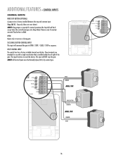
.../EDGE INPUTS (P6-7-8 AND 9)
LOOP INPUTS
OPEN INPUT AND EXIT LOOP These terminals are intended for use as telephone entry systems, radio receivers (open only applications), exit loop detectors, keypads and 7-day timers may be wired to this input. INTERRUPT LOOP INPUT TERMINAL AND COMMON This input functions to open limit. Latching this input will continue to...
LA400 Manual - Page 39

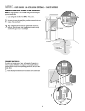
... with the LA400 to control box depending on three sides. (Requires mounting channel. Secure the control box cover with reflector and mounting brackets
+24 Vdc
SENSING EDGES
DESCRIPTION Miller MG020 2-wire electric edge... OVLD
COM
F1 20A 32V
MOV1 JMPR2 DB1
C64 U2
R9 D1
JMPR1
D4 D2
FUSE OPEN
BATT 2 BATT 1
Accessory Power
AUXILIARY OUTPUT POWER FOR OPTIONAL DEVICES
(2) +24 Vdc Outputs...
LA400 Manual - Page 43
...R1ÿ 1
21 24 FORCE
BIPART DELAY
TIMER TO SINGLE CLOSE BUTTON
OPEN
CONTROL INPUTS
R1ÿÿ
23
F4
ACCESSORY OVLD
K4 F5 D21
K3 D8
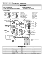
...OPEN (EXIT LOOP) SINGLE BUTTON RESET S T O P COMMON (+24VDC) COMMON (+24VDC)
7
SHADOW LOOP INTERRUPT LOOP COMMON (+24VDC)
8
NOTE: Yellow/green wire must
9
be disconnected when earth
ground rod is installed.
16
15
NOTE: Batteries must be connected...
LA400 Manual - Page 44

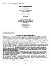
... not set. 3) Accessory device wired to -Close not turned on. 2) Gate has opened on next page to -Close section for proper installation of operator arm.
Check STOP connections. Replace control board. Voltage must be >23 V at battery connection.
Replace motor. Clear gate from obstruction. Check for adjustment instructions. Replace arm. Use reference chart on Obstruction...
LA400 Manual - Page 46
... TO, THE GARAGE DOOR OR GARAGE DOOR HARDWARE, INCLUDING BUT NOT LIMITED TO THE DOOR SPRINGS, DOOR ROLLERS, DOOR ALIGNMENT OR HINGES. UNDER NO CIRCUMSTANCES SHALL SELLER BE LIABLE FOR CONSEQUENTIAL, INCIDENTAL OR SPECIAL DAMAGES ARISING IN CONNECTION WITH USE, OR INABILITY TO USE, THIS PRODUCT. Technical Support Group 6050 S. The proper operation of this product is free from defect in...
LA400 Manual - Page 47
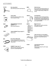
... Commercial Protector System® (Direct Connect): Maximum range is a replacement battery for a Open, Close, Stop command of remote controls. To order visit www.liftmaster.com 46 OPEN
LM202
02101
OPEN OPEN
OPEN
370LM
1-Button Station:
Steel enclosure wired station will allow the gate operator to push the gate open.
Recommended for free exit only.
Requires separate power supply...
LA400 Push to Open Addendum Manual - Page 2
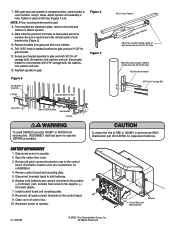
... and connect red wires to the positive (+) terminals (red). Connect black wires to the control
board.
Remove brackets from electrocution, DISCONNECT electrical power to persons use to the negative (-) terminals (black). 7. Drill 13/32" holes in the vertical center of FIRE or INJURY to operator BEFORE proceeding.
Open the control box cover. 3. Install control board and...
Similar Questions

Can't Set Limits
When pressing learn limits button to save after setting limits, open limit light flashes again, star...
When pressing learn limits button to save after setting limits, open limit light flashes again, star...
(Posted by nhidalgo 1 year ago)

Garage Door Opens After Shutting.
My Lift master 8550 inside keypad is Inside wall pad is model #880LM. outside keypad Model # is 877M...
My Lift master 8550 inside keypad is Inside wall pad is model #880LM. outside keypad Model # is 877M...
(Posted by BONNIECA92 2 years ago)

Car To La400
how do you connect the La400 to a door opener in the car
how do you connect the La400 to a door opener in the car
(Posted by vanvrancken 6 years ago)

How To Install Cable Wire For Garage Door Opener Model 3800
(Posted by laedmhrink 10 years ago)