Gateway MT6840 Support Question
Gateway MT6840 Support Question
Find answers below for this question about Gateway MT6840 - MT - Core Duo 2 GHz.Need a Gateway MT6840 manual? We have 7 online manuals for this item!
Question posted by arkaNav on March 20th, 2014
How To Remove Motherboard In Gateway Mt6840
The person who posted this question about this Gateway product did not include a detailed explanation. Please use the "Request More Information" button to the right if more details would help you to answer this question.
Current Answers
Related Gateway MT6840 Manual Pages
8511725 - Gateway Service Guide - Page 9
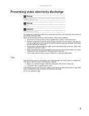
...static electricity, also known as carpeted floors, plastic, and packing foam. • Remove components from their edges.
Both types of tape. Do not use them. Before performing...follow these guidelines:
• Avoid static-causing surfaces such as electrostatic discharge (ESD). www.gateway.com
Preventing static electricity discharge
Warning
To avoid exposure to a bare
metal part of the...
8511725 - Gateway Service Guide - Page 11
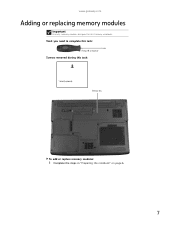
Tools you need to complete this task:
Phillips #0 screwdriver
Screws removed during this Gateway notebook. www.gateway.com
Adding or replacing memory modules
Important
Use only memory modules designed for this task:
1 black (keyboard)
Memory bay
To add or replace memory modules:
1 Complete the steps in "Preparing the notebook" on page 6.
7
8511725 - Gateway Service Guide - Page 13
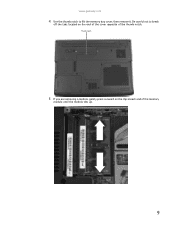
Be careful not to lift the memory bay cover, then remove it.
Thumb notch
5 If you are removing a module, gently press outward on the end of the cover opposite of the memory
module until the module tilts up.
9 www.gateway.com
4 Use the thumb notch to break
off the tabs located on the clip at each end of the thumb notch.
8511725 - Gateway Service Guide - Page 15
Tip
The screw hole is marked with a K.
www.gateway.com
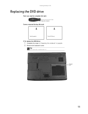
Replacing the DVD drive
Tools you need to complete this task:
Phillips #0 screwdriver
Screws removed during this task:
1 black (keyboard)
1 black (DVD drive)
To replace the DVD drive:
1 Complete the steps in "Preparing the notebook" on page 6. 2 Remove the keyboard screw. Keyboard screw
11
8511725 - Gateway Service Guide - Page 17
...
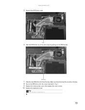
7 Slide the new DVD drive into the drive bay. www.gateway.com
5 Remove the DVD drive screw. Screw
6 Slide the DVD drive out of the drive bay by pushing on the DVD bracket.
Tip
The screw hole is marked with the screw removed in the bay. 8 Secure the DVD drive with a K.
13
Make...
8511725 - Gateway Service Guide - Page 19
Thumb notch
15
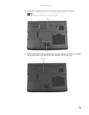
Screws
Screws
4 Use the thumb notch to break
off the tabs located on your model, not all screws may be removed). Be careful not to lift the memory bay cover, then remove it. www.gateway.com
3 Loosen the six memory bay cover screws (these screws cannot be captive. Tip
Depending on the end of the cover opposite of the thumb notch.
8511725 - Gateway Service Guide - Page 21
...gateway.com
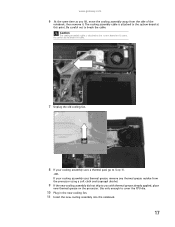
6 .At the same time as you with thermal grease already applied, place
new thermal grease on the processor.
Be careful not to break the cable.
7 Unplug the old cooling fan.
8 If your cooling assembly uses a thermal pad, go to Step 10.
-ORIf your cooling assembly uses thermal grease, remove... away from the side of the
notebook, then remove it. Be careful not to cover the CPU ...
8511725 - Gateway Service Guide - Page 23
www.gateway.com
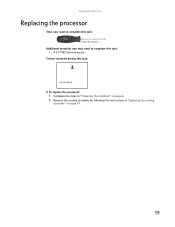
Replacing the processor
Tools you need to complete this task:
Phillips #0 screwdriver
Additional materials you may need to complete this task:
• X-23-7762 thermal grease
Screws removed during this task:
1 black (keyboard)
To replace the processor:
1 Complete the steps in "Preparing the notebook" on page 6. 2 Remove the cooling assembly by...
8511725 - Gateway Service Guide - Page 25
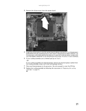
... thermal grease residue from the cooling assembly using a soft cloth and isopropyl alcohol.
7 Place new thermal grease on page 14.
21 www.gateway.com
4 Remove the old processor from the system board.
5 Install the new processor onto the system board making sure that Pin 1 on the processor
(indicated by the ...
8511725 - Gateway Service Guide - Page 26
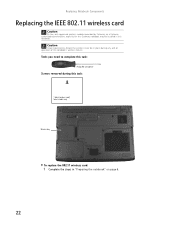
..., explicitly for this Gateway notebook may be in place during this task:
1 black (wireless card) Select models only
Wireless bay
To replace the 802.11 wireless card:
1 Complete the steps in "Preparing the notebook" on page 6.
22
Tools you need to complete this task:
Phillips #0 screwdriver
Screws removed during any and all...
8511725 - Gateway Service Guide - Page 27

www.gateway.com
2 Loosen the wireless bay cover screw (this screw cannot be removed), then remove the
wireless bay cover. Screw
3 Unplug the two antenna cables.
4 Move the antenna cables out of the way.
23
8511725 - Gateway Service Guide - Page 31

Screws
Screws
27 www.gateway.com
3 Slide the old hard drive kit out of the notebook.
4 If the hard drive shipped to you without a new cover, remove the four screws that secure the hard drive to Step 8.
-OR-
If the hard drive shipped to you already attached to a new cover, go to the hard drive bay cover.
8511725 - Gateway Service Guide - Page 33
... cover:
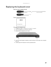
1 Complete the steps in "Preparing the notebook" on page 6. 2 Turn the notebook over so the top is facing up. 3 Remove the two keyboard cover screws.
Phillips #0 screwdriver
Screws removed during this task:
Flat-blade driver
- OR -
www.gateway.com
Replacing the keyboard cover
Tools you need to the fully opened position.
29
8511725 - Gateway Service Guide - Page 35
OR -
www.gateway.com
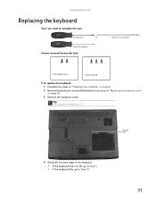
Replacing the keyboard
Tools you need to Step 10.
31 Phillips #0 screwdriver
Screws removed during this task:
Flat-blade driver
- Keyboard screw
4 Gently lift the back edge...(keyboard)
To replace the keyboard:
1 Complete the steps in "Preparing the notebook" on page 6. 2 Remove the keyboard cover by following the instructions in "Replacing the keyboard cover"
on page 29...
8511725 - Gateway Service Guide - Page 37
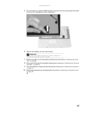
...LCD panel to the fully opened
position.
10 With the back edge of these screws may be removed), then remove the
wireless bay cover. Tip
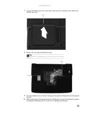
Depending on the keyboard features, one or both of the keyboard ...Be careful not to release
the keyboard retaining tabs.
Screw
8 Remove the two optional keyboard screws. www.gateway.com
7 Loosen the wireless bay cover screw (this screw cannot be absent.
8511725 - Gateway Service Guide - Page 39
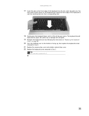
... hole is facing up, then replace the keyboard screws
removed in Step 8.
21 Replace the memory bay cover and wireless network bay cover. 22 Replace the keyboard screw removed in "Replacing the keyboard
cover" on page 29.
...place. You
may need to press down until it is flat all the way across. www.gateway.com
17 Insert the tabs on the keyboard keys along the front edge of the keyboard into the ...
8511725 - Gateway Service Guide - Page 41
... not reusable.
7 Replace the palm rest (if removed) by following the instructions in "Replacing the palm
rest" on page 56.
8 Remove the LCD panel (if removed) by following the instructions in "Replacing the LCD ... the system board. Important
Use only CMOS batteries designed for this Gateway notebook. www.gateway.com
5 Use your fingers to touch or damage any other components.
6 Plug the new...
8511725 - Gateway Service Guide - Page 47
www.gateway.com
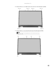
6 Remove the four or six rubber inserts from the front of the LCD panel assembly. Rubber insert
Rubber insert Rubber insert
Rubber insert
Rubber insert
Rubber insert
7 Remove the four or six screws from the front of the LCD panel assembly. Screw
Screw
Screw
Screw
Screw
Screw
43
Tip
On select...
8511725 - Gateway Service Guide - Page 49

... then insert the new one. 12 Connect the cables to the new inverter. 13 If you removed the bracket in Step 9, replace it, then replace the two screws. 14 Press the front ...31.
19 Replace the keyboard cover by following the instructions in place. www.gateway.com
10 Unplug both cables from the front of the LCD panel assembly removed in Step 7. 16 Replace the four or six rubber inserts onto the front...
8511725 - Gateway Service Guide - Page 51
www.gateway.com
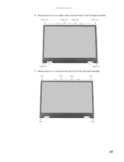
6 Remove the four or six rubber inserts from the front of the LCD panel assembly.
Rubber insert
Rubber insert Rubber insert
Rubber insert
Rubber insert
Rubber insert
7 Remove the four or six screws from the front of the LCD panel assembly. Screw
Screw
Screw
Screw
Screw
Screw
47
Similar Questions

How To Do A Full Recovery On Gateway Laptop Mt6840 Using
(Posted by rhinerad 9 years ago)

What Screw Need To Be Removed Replacing Gateway Nv55c Keyboard
(Posted by jar41samira 9 years ago)


Notebook
What i sthe difference between the Gateway MT6840 and the Gateway MT6728. Is one better then the oth...
What i sthe difference between the Gateway MT6840 and the Gateway MT6728. Is one better then the oth...
(Posted by corrine2020 12 years ago)