
Dell PowerEdge T610 Support Question
Dell PowerEdge T610 Support Question
Find answers below for this question about Dell PowerEdge T610.Need a Dell PowerEdge T610 manual? We have 15 online manuals for this item!
Question posted by ghraypo on November 12th, 2013
Poweredge T610 How To Clear Lcd Panel Messages
The person who posted this question about this Dell product did not include a detailed explanation. Please use the "Request More Information" button to the right if more details would help you to answer this question.
Current Answers
Related Dell PowerEdge T610 Manual Pages
Information Update - Page 1
... information, see the knowledge base article at support.microsoft.com: • Systems running Windows Server 2008 do not support iSCSI boot when they have been removed.
On the PowerEdge T610 system, the labels are located on the information panel on the front of the system. In addition, iSCSI boot does not work with your...
Hardware Owner's Manual - Page 3

...-Panel Features and Indicators 12 LCD Panel Features 14
Home Screen 16 Setup Menu 16 View Menu 17 Hard-Drive Indicator Patterns for RAID 18 Back-Panel Features and Indicators 20 Power Indicator Codes 21 NIC Indicator Codes 24 LCD Status Messages 24 Viewing Status Messages 25 Removing LCD Status Messages 25 System Messages 37 Warning Messages 54 Diagnostics Messages 54 Alert Messages...
Hardware Owner's Manual - Page 13

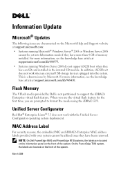
... To force an ungraceful shutdown, press and hold the power button for five seconds.
When one of these buttons is pushed, the LCD panel on the front and the system status indicator on the back flashes blue until one of memory installed in the system. Allows you ... depending on .
About Your System
13 The power button controls the DC power supply output to navigate the control panel LCD menu.
Hardware Owner's Manual - Page 14
... or two optional SATA DVD-ROM or DVD+RW drives.
See "LCD Status Messages" for information on the LCD panel. One optional half-height (using one drive bay) or full-height drive (using two drive bays). The LCD backlight will remain off if LCD messaging is operating correctly or when the system needs attention. NOTE: DVD devices...
Hardware Owner's Manual - Page 15

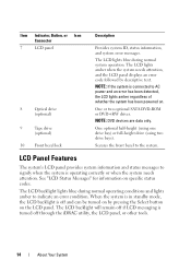
LCD Panel Features
2 3
1
4
Item
Buttons
Description
1
Left
Moves the cursor back in one-step increments.
2
Select
Selects ... to repeat the cycle.
4
System identification Turns the system ID mode on and off . About Your System
15 Figure 1-2. During message scrolling:
• Press once to increase scrolling speed.
• Press again to stop.
• Press again to return to ...
Hardware Owner's Manual - Page 16
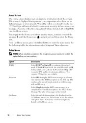
...items that matches the IPMI description in this format. Select Simple to display LCD error messages in standby mode, the LCD backlight will turn off after five minutes of the three navigation buttons (...press the Select button to display by default on the Setup and View submenus. See "LCD Status Messages" for information on the Home screen.
16
About Your System Setup Menu
NOTE: When ...
Hardware Owner's Manual - Page 21
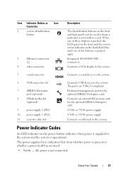
...on the back flash blue until one of these buttons is pushed, the LCD panel on the front and the system status indicator on the power button indicates ...system identification
button
3
Ethernet connectors
(2)
4
video connector
Description
The identification buttons on the front and back panels can be used to the system. Connects a VGA display to the system.
5
serial connector
Connects ...
Hardware Owner's Manual - Page 25
... seconds, reconnect the power cable, and restart the system.
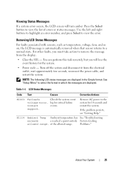
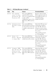
LCD Status Messages
Code Text
Causes
Corrective Actions
E1000
Failsafe
Check the system event...Clear the SEL - Table 1-1. log for critical failure
Contact
events.
Viewing Status Messages
If a system error occurs, the LCD screen will lose the event history for the system.
• Power cycle - Removing LCD Status Messages...
Hardware Owner's Manual - Page 26
... "Troubleshooting the
has failed.
E1216
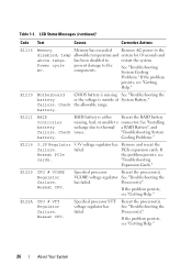
3.3V Regulator 3.3V voltage regulator has Remove and reseat the
failure. Specified processor VTT voltage regulator has failed. Table 1-1. LCD Status Messages (continued)
Code Text
Causes
Corrective Actions
E1116
Memory
Memory has exceeded Remove AC power to
restart the system. has been disabled to the
disabled, temp...
Hardware Owner's Manual - Page 27
... the on-board voltage regulators failed.
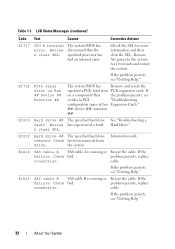
If the problem persists, see "Getting Help." E1310
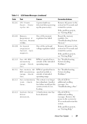
Fan ## RPM exceeding range.
heating.
Check LCD for additional scrolling messages. About Your System
27 LCD Status Messages (continued)
Code Text
Causes
Corrective Actions
E122C CPU Power Fault.
Check fan. Check fan redundant.
E122E
On-board regulator...
Hardware Owner's Manual - Page 30
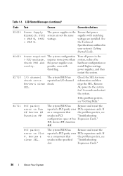
...power supplies, and then restart the system. E1711
PCI parity error on Slot #.
Review & clear SEL. If
on a component that
the problem persists, see
resides in PCI
"Troubleshooting
configuration ...with matching
= ### W, PSU2 wattage. Table 1-1. LCD Status Messages (continued)
Code Text
Causes
Corrective Actions
E1626
Power Supply The power supplies in
your system's Getting...
Hardware Owner's Manual - Page 31
...system
for more
determined there has been information and then
a fatal error in bus clear the SEL. for more
Bus ## Dev ## reported a chipset internal information and then...Chipset IERR The system BIOS has
Check the SEL for 10 seconds and restart
the system.
LCD Status Messages (continued)
Code Text
Causes
Corrective Actions
E1712
PCI system error on a component that resides in...
Hardware Owner's Manual - Page 32
LCD Status Messages (continued)
Code Text
Causes
Corrective Actions
E1717
CPU # internal error.
E171F
PCIe fatal error on a component that the ...persists, see "Getting Help."
32
About Your System If the problem persists, see "Getting Help." Check bad. Review & clear SEL. Review has experienced a fault. & clear SEL. Remove AC power to the system for more information and then...
Hardware Owner's Manual - Page 33
LCD Status Messages (continued)
Code Text
Causes
Corrective Actions
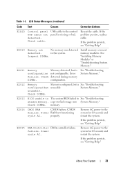
E1A1D
Control panel USB cable not detected.
E2011
Memory
Memory detected,... memory.
Check cable.
Check DIMMs.
E2013 BIOS unable to The system BIOS failed to the control panel is
configuration not configurable. CMOS
failure.
System Memory." copy its flash image into System Memory."
About...
Hardware Owner's Manual - Page 36
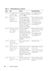
... will not log anymore If the problem persists, SBEs until the system is unable to the
disabled memory
system for details
Review & clear and is see "Troubleshooting
errors. LCD overflow message. A Check the SEL for details
maximum of events Check the SEL for 10 seconds and
mirroring because it has restart the system...
Hardware Owner's Manual - Page 66
... screen.
66
Using the System Setup Program and UEFI Boot Manager
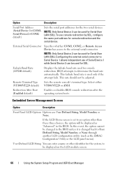
Remote Terminal Type Sets the remote console's terminal type. Embedded Server Management Screen
Option
Description
Front Panel LCD Options Options are User Defined String, Model Number, or None.
BIOS attempts to the external serial connector. This rate should not be changed in...
Hardware Owner's Manual - Page 155

.... For all external cables are securely attached to servicing that appear onscreen. Read and follow the safety instructions that all other startup issues, note the LCD panel messages and any video output. Troubleshooting External Connections
Ensure that came with the product. You should only perform troubleshooting and simple repairs as authorized in UEFI...
Hardware Owner's Manual - Page 162

... Replace the expansion card stabilizer. If the replacement fan does not operate, see "LCD Status Messages") or the diagnostic software.
2 Turn off the system and attached peripherals, and ... certified service technician. Troubleshooting a Fan
CAUTION: Many repairs may only be done by the LCD panel (see "Getting Help."
162
Troubleshooting Your System See "Opening the System."
4 Remove the ...
Hardware Owner's Manual - Page 163
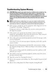
... and then reconnect the system to the memory settings, if needed. See "Using Dell™ PowerEdge™ Diagnostics." Make any changes to power.
3 Turn on the system and attached peripherals and note the messages on the screen or LCD panel.
Wait at startup without video output. See "Removing the Cooling Shroud." See "General Memory...
Hardware Owner's Manual - Page 199
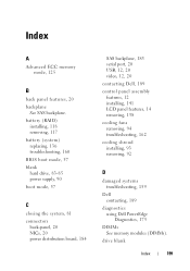
... port, 20 USB, 12, 20 video, 12, 20
contacting Dell, 189
control panel assembly features, 12 installing, 141 LCD panel features, 14 removing, 138
cooling fans removing, 94 troubleshooting, 162
cooling shroud installing, 93 removing, 92
D
damaged systems troubleshooting, 159
Dell contacting, 189
diagnostics using Dell PowerEdge Diagnostics, 175
DIMMs See memory modules (DIMMs).
Similar Questions

How Do I Clear A Message On My Lcd Panel On My Dell Poweredge T610
(Posted by nadCaes 9 years ago)
How To Clear The Error Message On Dell T610 Poweredge
(Posted by kahec 9 years ago)

How To Clear Bios Related Errors From Poweredge 2950 Lcd Panel
(Posted by thken 10 years ago)

Why There Is Amber Colour On The Lcd Panel.
Hi.. my LCD panel on the rack server shows nothing (blank) in amber color light. When I press the "i...
Hi.. my LCD panel on the rack server shows nothing (blank) in amber color light. When I press the "i...
(Posted by hairil 12 years ago)