Dell Latitude E6330 Support Question
Dell Latitude E6330 Support Question
Find answers below for this question about Dell Latitude E6330.Need a Dell Latitude E6330 manual? We have 5 online manuals for this item!
Question posted by mjbea on February 2nd, 2014
How,to Remove Lcd Assembly On Latitude E 6330
The person who posted this question about this Dell product did not include a detailed explanation. Please use the "Request More Information" button to the right if more details would help you to answer this question.
Current Answers
Related Dell Latitude E6330 Manual Pages
Statement of Volatility - Page 1
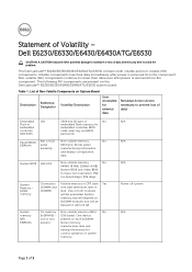
...N/A N/A Power off system
N/A
Page 1 of LCD Non-volatile memory
No
EEPROM
panel
64K bytes.
Table 1. Stores panel
assembly
manufacturing information
and display configuration
data. DDR3 memory
... GB to retain their data immediately after power is removed from the component. The Dell Latitude™ E6230/E6330/E6430/E6430ATG/E6530 contains both modules
will be populated...
Owner's Manual - Page 4
... ExpressCard Cage...29 Installing the ExpressCard Cage...30 Removing the Speakers...31 Installing the Speakers...32 Removing the Display-Hinge Covers...32 Installing the Display Hinge Covers...33 Removing the Display Assembly...33 Installing the Display Assembly...36 Removing the System Board...36 Installing the System Board...38 Removing the Heat Sink...39 Installing the Heat Sink...
Owner's Manual - Page 20
Remove the screws that secure the keyboard to access the keyboard cable. 7. Disconnect the keyboard cable from the computer. 20 5. Remove the keyboard from the system board. 8. Lift and turn the keyboard to palmrest assembly. 6.
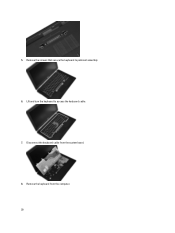
Owner's Manual - Page 26

Disconnect the LED-board cable from the system board.
26 Remove the screws that secure the palmrest assembly to the base of the computer.
5. Remove the screws that secure the palmrest assembly to the front of the computer.
4. Disconnect the touchpad cable from the system board.
6. e) optical drive f) base cover g) keyboard trim h) keyboard i) bluetooth module 3.
Owner's Manual - Page 33

... b) bluetooth module c) keyboard d) keyboard trim e) base cover f) optical drive g) hard drive h) battery i) ExpressCard j) SD card 3.
Follow the procedures in After Working Inside Your Computer.
Removing the Display Assembly
1. f) base cover g) keyboard trim h) keyboard i) bluetooth module j) palmrest 3. Tighten the screws to secure the display hinge covers to the computer.
4.
Owner's Manual - Page 34

... b) ExpressCard c) battery d) hard drive e) optical drive f) base cover g) keyboard trim h) keyboard i) bluetooth module j) palmrest 3. Remove the screws that secures the left display hinge to the computer.
5. Remove the screw that secure the display assembly to the computer.
6. Remove the screws that secure the Low-Voltage Differential Signaling (LVDS) support bracket.
34 Release the...
Owner's Manual - Page 35
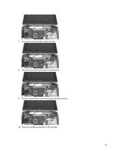
Lift up and remove the LVDS support bracket. 8. Disconnect the LVDS cable from the opening on the system board. 10. Pull the antenna cables from the system board. 9. Remove the display assembly from the computer.
35 7.
Owner's Manual - Page 36
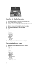
... trim e) base cover f) optical drive g) hard drive h) battery i) ExpressCard j) SD card 8. Removing the System Board
1. Remove:
a) SD card b) ExpressCard c) battery d) hard drive e) optical drive f) base cover g) keyboard... in After Working Inside Your Computer. Tighten the screws to secure the display assembly to the system board. 3. Route the antennae cables through their routing channel....
Owner's Manual - Page 37

Lift the left edge of system board partially to the computer.
7. Disconnect the speaker cable from the system board.
5. Remove the screws that secure the system board to a 45-degree angle. 37 m) display assembly 3. Disconnect the ExpressCard cable from the system board.
6. Disconnect the coin-cell battery cable from the system board.
4.
Owner's Manual - Page 41
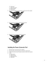
k) media board l) display hinge covers m) display assembly n) system board 3. Remove the power connector port from the computer.
5. Install:
a) system board b) display assembly c) display hinge covers d) media board
41 Installing the Power-Connector Port
1. Tighten the screw to secures the power-connector bracket to the computer.
4.
Remove the screw that secures the power connector...
Owner's Manual - Page 42

... trim i) base cover j) optical drive k) hard drive l) battery m) ExpressCard n) SD card 5.
Follow the procedures in After Working Inside Your Computer. Remove the screw that secures the I/O board to the computer.
4. Remove:
a) SD card b) ExpressCard c) battery d) hard drive e) optical drive f) base cover g) keyboard trim h) keyboard i) bluetooth module j) palmrest k) media board l) display...
Owner's Manual - Page 43

... edges of the display bezel.
4. Install:
a) system board b) display assembly c) display hinge covers d) media board e) palmrest f) bluetooth module g) keyboard h) keyboard trim i) base cover j) optical drive k) hard drive l) battery m) ExpressCard n) SD card 4. Installing the I /O board. 3. Removing the Display Bezel
1. Remove the battery. 3. Place the I/O board in After Working Inside...
Owner's Manual - Page 44

... the procedures in Before Working Inside Your Computer. 2. Follow the procedures in After Working Inside Your Computer. Remove the battery. 3. Install the battery. 5. Remove the screws that secure the display panel to the display assembly.
44 Remove the display bezel from the top corner, press on the left and right edges of the display...
Owner's Manual - Page 45
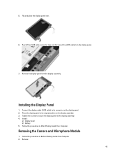
... After Working Inside Your Computer. Connect the display cable (LVDS cable) to the display assembly. 4.
Peel off the LVDS cable connector tape and disconnect the LVDS cable from the display assembly. Installing the Display Panel
1. Install :
a) display bezel b) battery 5. Removing the Camera and Microphone Module
1. 5. Follow the procedures in Before Working Inside Your...
Owner's Manual - Page 46
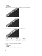
... 5. Follow the procedures in After Working Inside Your Computer. 46 Installing the Camera and Microphone Module
1. Remove the screws that secure the camera and microphone module to the camera. 4. Connect the camera and microphone cable to the display assembly.
4. a) battery b) display bezel 3. Disconnect the camera and microphone module cable from the display...
Owner's Manual - Page 47
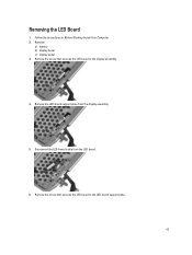
...-board support plate from the LED board.
6. Remove the screw that secures the LED board to the LED-board support plate.
47 Remove the screw that secures the LED board to the display assembly.
4. Disconnect the LED-board cable from the display assembly.
5. Removing the LED Board
1. Remove:
a) battery b) display bezel c) display panel 3. Follow the procedures...
Specifications - Page 1
...between select laptops. Business-Class Control
Manage and maintain your network and removable media. Strengthen security with one common dock, AC adapter and accessories across your Latitude E6330 with ...processors, high-bandwidth DDR3 memory and Intel® HD graphics.
The Latitude E6330 180 degree LCD movement and optional backlit keyboard enable users to work . Automate manual...
Specifications - Page 2
... copy of Low-Halogen Electronics (BFR-/CFR-/PVC-free)'. Discover leading-edge laptops at Dell.com/Latitude
1. Significant system memory may be less. 10. Feature Processor Options Operating ... or Russia. 5. Based on configuration and manufacturing variability. Factory Image load. D ell Latitude laptops are required)
Intel® HD Graphics 4000 (for Intel Core i3/i5/i7 3xxxM processors...
User Guide - Page 9
...
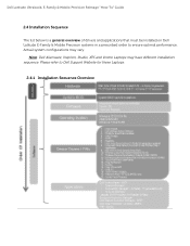
2.4 Installation Sequence
The list below is a general overview of drivers and applications that must be installed on Dell Latitude E-Family & Mobile Precision systems in a prescribed order to Dell Support Website for these Laptops.
2.4.1 Installation Sequence Overview
Please refer to ensure optimal performance. Actual system configurations may have different installation sequence. Note...
User Guide - Page 24
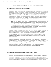
...for WLAN controllers featured in Dell Latitude E-Family & Mobile Precision systems. ...web site (support.dell.com). Dell Latitude Ultrabook, E-Family & Mobile Precision Reimage ...can quickly connect your laptop to uninstall Dell Control...do not support the Bluetooth controllers featured on Latitude E-Family & Mobile Precision systems. To ... no cables between the laptop and TV/Projector. Customers...
Similar Questions

Num Lock Function On The Latitude E6330
Where is the num lock key on the dell latitude e6330 laptop ? it is on and I need to turn it off
Where is the num lock key on the dell latitude e6330 laptop ? it is on and I need to turn it off
(Posted by Melvadegiorgio87 9 years ago)

How To Remove Dell Latitude E6430 From Docking Station
(Posted by ldvreti 9 years ago)

How To Remove Keyboard Dell Latitude 2120 Hard Drive
(Posted by ftschnigo 10 years ago)
My Friend Gave Me His Company Computer (latitude E6330), I Installed Windows Wit
I did not get drivers disk with the system, where can I get that from
I did not get drivers disk with the system, where can I get that from
(Posted by alstonbearded 10 years ago)