User Guide
Page 2
Stop If you ever have to remove the main system unit cover, observe the following conditions: 1 If the power cord or plug is plugged back in damage and may result in . (Apres le couvercle a enleve, visse le ... instructions. Improper adjustment of the following precautions: 1 The power supply cord must be unplugged before the main system unit cover is removed. (Separe le cordon d'alimentation et puis enleve le couvercle.) 2 Once removed, the cover must be replaced and screwed in position before the power supply cord is damaged or frayed. 2 If liquid has...
Stop If you ever have to remove the main system unit cover, observe the following conditions: 1 If the power cord or plug is plugged back in damage and may result in . (Apres le couvercle a enleve, visse le ... instructions. Improper adjustment of the following precautions: 1 The power supply cord must be unplugged before the main system unit cover is removed. (Separe le cordon d'alimentation et puis enleve le couvercle.) 2 Once removed, the cover must be replaced and screwed in position before the power supply cord is damaged or frayed. 2 If liquid has...
User Guide
Page 8
... ...A-2 Audio ...A-2 Floppy Disk Drive A-3 Display & Monitor A-3 Keyboard ...A-4 Mouse ...A-4 Appendix B. Approval Statements Battery Warning Instruction B-1 Fuse Warning Instruction B-1 Laser Product ...B-2 viii Chapter 4 Installing and Removing Drives Removing the Cover 4-1 Replacing the Cover 4-3 Installing an Expansion Card 4-4 Installing an Additional Hard Disk Drive 4-6 Installing the 5.25-inch Device in the Peripheral Bay 4-9 Chapter 5 Using the Restore...
... ...A-2 Audio ...A-2 Floppy Disk Drive A-3 Display & Monitor A-3 Keyboard ...A-4 Mouse ...A-4 Appendix B. Approval Statements Battery Warning Instruction B-1 Fuse Warning Instruction B-1 Laser Product ...B-2 viii Chapter 4 Installing and Removing Drives Removing the Cover 4-1 Replacing the Cover 4-3 Installing an Expansion Card 4-4 Installing an Additional Hard Disk Drive 4-6 Installing the 5.25-inch Device in the Peripheral Bay 4-9 Chapter 5 Using the Restore...
User Guide
Page 23
...Turn off the computer and peripheral devices including the monitor and printer. Then disconnect any of your computer. Removing the Cover You need to the computer. To remove the cover, follow these steps: 1. Then disconnect the computer from its internal components. First of all, disconnect the...power cable from the electrical outlet and from any telecommunications links, networks, or modems before performing any cables connected to remove the cover of the procedures described in your system to access its power source and from the back panel. Chapter 1 2. Turn off ...
...Turn off the computer and peripheral devices including the monitor and printer. Then disconnect any of your computer. Removing the Cover You need to the computer. To remove the cover, follow these steps: 1. Then disconnect the computer from its internal components. First of all, disconnect the...power cable from the electrical outlet and from any telecommunications links, networks, or modems before performing any cables connected to remove the cover of the procedures described in your system to access its power source and from the back panel. Chapter 1 2. Turn off ...

User Guide
Page 24
If you are not properly grounded, you could generate an electric shock when you remove the cover. 3. Set the cover aside. To open the system cover, remove two screws on the back panel of your system every time you touch a component. 4-2 Installing and Removing Drives Slide the cover toward the rear to ground yourself by touching your computer. 4. NOTE Be sure to free it from the system and lift it off until can be removed completely.
If you are not properly grounded, you could generate an electric shock when you remove the cover. 3. Set the cover aside. To open the system cover, remove two screws on the back panel of your system every time you touch a component. 4-2 Installing and Removing Drives Slide the cover toward the rear to ground yourself by touching your computer. 4. NOTE Be sure to free it from the system and lift it off until can be removed completely.

User Guide
Page 25
Installing and Removing Drives 4-3 Hold the cover with the screws you removed. 3. Reconnect the monitor, keyboard, mouse, and any other peripheral device's cable connectors to your hands and gently put it down to the chassis on the rear position (about 1cm) from the front bezel, then push it to the front. 2. Tighten the cover to replace the cover: 1. Replacing the Cover Follow these steps to the chassis with your system.
Installing and Removing Drives 4-3 Hold the cover with the screws you removed. 3. Reconnect the monitor, keyboard, mouse, and any other peripheral device's cable connectors to your hands and gently put it down to the chassis on the rear position (about 1cm) from the front bezel, then push it to the front. 2. Tighten the cover to replace the cover: 1. Replacing the Cover Follow these steps to the chassis with your system.
User Guide
Page 26
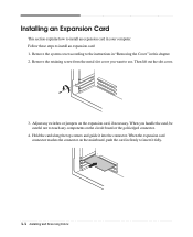
...any components on the mainboard, push the card in firmly to insert it into the connector. Remove the system cover according to the instructions in "Removing the Cover" in your computer. Then lift out the slot cover. 3. When you want to use. Hold the card along the top corners and guide ...it fully. 4-4 Installing and Removing Drives Follow these steps to install an expansion card: 1. When the expansion card...
...any components on the mainboard, push the card in firmly to insert it into the connector. Remove the system cover according to the instructions in "Removing the Cover" in your computer. Then lift out the slot cover. 3. When you want to use. Hold the card along the top corners and guide ...it fully. 4-4 Installing and Removing Drives Follow these steps to install an expansion card: 1. When the expansion card...

User Guide
Page 27
Replace the system cover according to the card. 7. 5. Connect any cables that should be attached to the instructions in "Replacing the Cover" in this chapter. Installing and Removing Drives 4-5 Secure the end of the card to the computer with retaining screw. 6.
Replace the system cover according to the card. 7. 5. Connect any cables that should be attached to the instructions in "Replacing the Cover" in this chapter. Installing and Removing Drives 4-5 Secure the end of the card to the computer with retaining screw. 6.

User Guide
Page 28
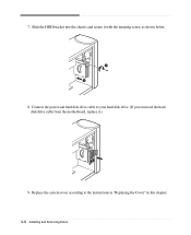
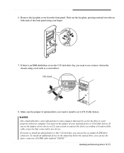
Remove the system cover according to the chassis and pull it . Remove the screw securing the HDD bracket to the instructions in "Removing the Cover" in this chapter. 2. You can install one additional hard disk drive in the HDD bracket attached on the chassis. Detach all cables from the hard disk drive. HDD bracket Hard disk drive 3. Installing an Additional Hard Disk Drive Your hard disk drive is installed in it out, as shown below. 4-6 Installing and Removing Drives Follow these steps to install the hard disk drive: 1.
Remove the system cover according to the chassis and pull it . Remove the screw securing the HDD bracket to the instructions in "Removing the Cover" in this chapter. 2. You can install one additional hard disk drive in the HDD bracket attached on the chassis. Detach all cables from the hard disk drive. HDD bracket Hard disk drive 3. Installing an Additional Hard Disk Drive Your hard disk drive is installed in it out, as shown below. 4-6 Installing and Removing Drives Follow these steps to install the hard disk drive: 1.
User Guide
Page 30
Replace the system cover according to your hard disk drive. (If you removed the hard disk drive cable from the motherboard, replace it with the retaining screw, as shown below. 8. Slide the HDD bracket into the chassis and secure it .) 9. Connect the power and hard disk drive cable to the instructions in "Replacing the Cover" in this chapter. 4-8 Installing and Removing Drives 7.
Replace the system cover according to your hard disk drive. (If you removed the hard disk drive cable from the motherboard, replace it with the retaining screw, as shown below. 8. Slide the HDD bracket into the chassis and secure it .) 9. Connect the power and hard disk drive cable to the instructions in "Replacing the Cover" in this chapter. 4-8 Installing and Removing Drives 7.
User Guide
Page 31
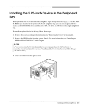
...more information, see "Installing an Additional Hard Disk Drive" in the bay, follow these steps: 1. Detach all cables from the system chassis. Remove the HDD bracket from the optical drive. NOTE If you want to install a 3.5-inch hard disk drive, you can add an optional device... system has two 5.25-inch horizontal peripheral bays. To install an optional device in this chapter. 2. Remove the cover according to install your 3.5-inch hard disk drive to the instructions in "Removing the Cover" in this chapter. If only one device (e.g., CD-ROM/DVDROM drive) is installed in the system...
...more information, see "Installing an Additional Hard Disk Drive" in the bay, follow these steps: 1. Detach all cables from the system chassis. Remove the HDD bracket from the optical drive. NOTE If you want to install a 3.5-inch hard disk drive, you can add an optional device... system has two 5.25-inch horizontal peripheral bays. To install an optional device in this chapter. 2. Remove the cover according to install your 3.5-inch hard disk drive to the instructions in "Removing the Cover" in this chapter. If only one device (e.g., CD-ROM/DVDROM drive) is installed in the system...
User Guide
Page 32
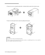
And then slide the optical drive from the chassis by pulling the front panel. Remove the front panel from the system. 5. Remove the screws securing the optical drive. 4. NOTES Be careful, not to split the power and LED cables from the front panel. 4-10 Installing and Removing Drives When you remove the front panel from the chassis, you have to carefully apart the cover not to bent or break the front panel.
And then slide the optical drive from the chassis by pulling the front panel. Remove the front panel from the system. 5. Remove the screws securing the optical drive. 4. NOTES Be careful, not to split the power and LED cables from the front panel. 4-10 Installing and Removing Drives When you remove the front panel from the chassis, you have to carefully apart the cover not to bent or break the front panel.
User Guide
Page 33
...the jumper of optional drive you want to new device. If you can use the spare connector of the cable connector that connected to use, remove it from the front panel. Push out the faceplate, pressing outward two tabs on both ends of the front panel using a tool such as... a screwdriver. Remove the faceplate cover from the chassis using your system recognizes the device according to CS, your finger. 7. NOTES Like a hard disk drive, most optional devices have...
...the jumper of optional drive you want to new device. If you can use the spare connector of the cable connector that connected to use, remove it from the front panel. Push out the faceplate, pressing outward two tabs on both ends of the front panel using a tool such as... a screwdriver. Remove the faceplate cover from the chassis using your system recognizes the device according to CS, your finger. 7. NOTES Like a hard disk drive, most optional devices have...

User Guide
Page 36
14. Replace the system cover according to the chassis. 15. Replace the HDD bracket to the instructions in "Replacing the Cover" in this chapter. 4-14 Installing and Removing Drives
14. Replace the system cover according to the chassis. 15. Replace the HDD bracket to the instructions in "Replacing the Cover" in this chapter. 4-14 Installing and Removing Drives
User Guide
Page 45
...'t set properly Adjust the brightness and contrast controls on the back of your Windows Help in Windows. The cable connecting the monitor to cover the hole. Click Start, click Control Panel, click Appearance and Themes, and then click Display. Or click the right mouse button on... a screen blanking utility installed or your mouse. Press any key or move your computer entered power management mode. Click the OK button. Remove the write-protection or use the Display Properties window. To change the display resolution or color depth? Floppy Disk Drive Cause Floppy disk drive...
...'t set properly Adjust the brightness and contrast controls on the back of your Windows Help in Windows. The cable connecting the monitor to cover the hole. Click Start, click Control Panel, click Appearance and Themes, and then click Display. Or click the right mouse button on... a screen blanking utility installed or your mouse. Press any key or move your computer entered power management mode. Click the OK button. Remove the write-protection or use the Display Properties window. To change the display resolution or color depth? Floppy Disk Drive Cause Floppy disk drive...
User Guide
Page 48
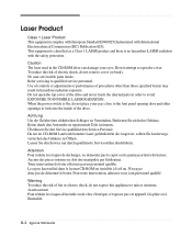
... à la pluie ou à l'humidité. This equipment is classified as a Class 1 LASER product and there is On, do not remove cover (or back). When the power switch is no hazardous LASER radiation with International Electrotechnical Commission (IEC) Publication 825]. Attention Pour reduire les risques de ... of the drive and never touch the internal parts in order to look into the inside . Do not attempt to open the top cover of fire or electric shock, do not expose this appliance to qualified service personnel. B-2 Approva Statements Laser Product Class 1 Laser Product ...
... à la pluie ou à l'humidité. This equipment is classified as a Class 1 LASER product and there is On, do not remove cover (or back). When the power switch is no hazardous LASER radiation with International Electrotechnical Commission (IEC) Publication 825]. Attention Pour reduire les risques de ... of the drive and never touch the internal parts in order to look into the inside . Do not attempt to open the top cover of fire or electric shock, do not expose this appliance to qualified service personnel. B-2 Approva Statements Laser Product Class 1 Laser Product ...


