
User Guide
Page 6
... STAR qualified products: • Produce less heat and reduce cooling loads, and warmer climates. • Automatically go into "display sleep" and "computer sleep" mode after 10 and 30 minute of inactivity respectively. • Wake the computer from sleep mode by the U.S. For lamp-specific disposal information, check www.lamprecycle.org. What...
... STAR qualified products: • Produce less heat and reduce cooling loads, and warmer climates. • Automatically go into "display sleep" and "computer sleep" mode after 10 and 30 minute of inactivity respectively. • Wake the computer from sleep mode by the U.S. For lamp-specific disposal information, check www.lamprecycle.org. What...
User Guide
Page 9
... Getting Started 7 Working safely and comfortably 8 Avoiding discomfort and injury from repetitive strain 8 Preparing power connections 9 Protecting from power source problems 9 Checking the voltage selection 10 Connecting to a broadband modem or network . . 11 Connecting a dial-up modem 11 Using the World Wide Web 12 Connecting to a Web site 13 Downloading files...
... Getting Started 7 Working safely and comfortably 8 Avoiding discomfort and injury from repetitive strain 8 Preparing power connections 9 Protecting from power source problems 9 Checking the voltage selection 10 Connecting to a broadband modem or network . . 11 Connecting a dial-up modem 11 Using the World Wide Web 12 Connecting to a Web site 13 Downloading files...
User Guide
Page 20
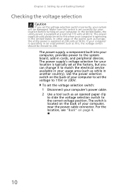
... voltage position. In the United States, the utility power is supplied at a nominal 115 volts at 50 Hz. Use the power selection switch on page 4. 10
... voltage position. In the United States, the utility power is supplied at a nominal 115 volts at 50 Hz. Use the power selection switch on page 4. 10

User Guide
Page 25
... or Gigabit Ethernet components. A DHCP network configuration uses a router to automatically assign IP addresses to obtain a permit and hire a licensed installer. Standard Ethernet runs at 10 Mbps, Fast Ethernet runs at 100 Mbps, and Gigabit Ethernet runs at three different speeds. Ethernet networking Wired Ethernet networking An wired Ethernet network consists...
... or Gigabit Ethernet components. A DHCP network configuration uses a router to automatically assign IP addresses to obtain a permit and hire a licensed installer. Standard Ethernet runs at 10 Mbps, Fast Ethernet runs at 100 Mbps, and Gigabit Ethernet runs at three different speeds. Ethernet networking Wired Ethernet networking An wired Ethernet network consists...
User Guide
Page 26
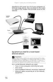
... • One broadband Internet connection (optional) • Ethernet cables connecting all Ethernet components should be either standard Ethernet (10 Mbps), Fast Ethernet (100 Mbps or 10/100), or Gigabit Ethernet (1000 Mbps or 10/100/1000). Cable/DSL modem Router 16 Equipment you need for a router-based Ethernet network Important For best results...
... • One broadband Internet connection (optional) • Ethernet cables connecting all Ethernet components should be either standard Ethernet (10 Mbps), Fast Ethernet (100 Mbps or 10/100), or Gigabit Ethernet (1000 Mbps or 10/100/1000). Cable/DSL modem Router 16 Equipment you need for a router-based Ethernet network Important For best results...
User Guide
Page 38
...; If you assigned IP addresses to the computers, make sure that all Ethernet components should be standard Ethernet (10 Mbps), Fast Ethernet (100 Mbps or 10/100 Mbps), or Gigabit Ethernet (1000 Mbps or 10/100/1000 Mbps). For more information about your Ethernet card, see the documentation that came with your network...
...; If you assigned IP addresses to the computers, make sure that all Ethernet components should be standard Ethernet (10 Mbps), Fast Ethernet (100 Mbps or 10/100 Mbps), or Gigabit Ethernet (1000 Mbps or 10/100/1000 Mbps). For more information about your Ethernet card, see the documentation that came with your network...

User Guide
Page 65
... the essential requirements and other relevant provisions of Conformity for compliance with Telecom's Telepermit requirements are dependent on -hook for a period of not less than 10 call attempts to the same number within any 30 minute period for which it provide any single manual call attempt. 4 Some parameters required for EU...
... the essential requirements and other relevant provisions of Conformity for compliance with Telecom's Telepermit requirements are dependent on -hook for a period of not less than 10 call attempts to the same number within any 30 minute period for which it provide any single manual call attempt. 4 Some parameters required for EU...

Service Guide
Page 8
... and keyboard connectors, COM1, one HDMI port, one VGA1 port, one optical SPDIFO port, four USB ports, one ESATA port, one PCI Express x16 slot, 10 USB 2.0 ports (4 USB ports and 3 USB 2.0 headers support additional 6 USB ports) and SATA support with single channel DDR2 800/667 MHz.
... and keyboard connectors, COM1, one HDMI port, one VGA1 port, one optical SPDIFO port, four USB ports, one ESATA port, one PCI Express x16 slot, 10 USB 2.0 ports (4 USB ports and 3 USB 2.0 headers support additional 6 USB ports) and SATA support with single channel DDR2 800/667 MHz.

Service Guide
Page 11
... to install the motherboard. 5 This concludes Chapter 1. Motherboard Components Table of Motherboard Components No Label 1 CPU Socket 2 CPU_FAN 3 DIMM1~2 4 ATX_POWER 5 GPIO32 6 GPIO33 7 CLR_CMOS1 8 PANEL1 9 F_USB1~3 10 SATA1~2 11 1394A1* 12 F_AUDIO1 13 PCIE16X 14 SPDIF1 15 PCIE1 16 ATX12V1 Component LGA775 socket for Intel® CoreTM2 Quad/Intel® CoreTM 2 Duo...
... to install the motherboard. 5 This concludes Chapter 1. Motherboard Components Table of Motherboard Components No Label 1 CPU Socket 2 CPU_FAN 3 DIMM1~2 4 ATX_POWER 5 GPIO32 6 GPIO33 7 CLR_CMOS1 8 PANEL1 9 F_USB1~3 10 SATA1~2 11 1394A1* 12 F_AUDIO1 13 PCIE16X 14 SPDIF1 15 PCIE1 16 ATX12V1 Component LGA775 socket for Intel® CoreTM2 Quad/Intel® CoreTM 2 Duo...

Service Guide
Page 14
Connects to eSATA devices Lights to a display devices(e.g.,external monitor, LCD projector). Rear view No Icon Component 1 Keyboard connector 2 HDMI Port 3 Monitor port 4 Line-out jack 5 Optical SPDIF 6 Mouse connector 7 Serial port 8 USB ports. 9 eSATA port 10 Network port 8 Description High Definition Multimedia Interface Connects to indicate the status of wireless LAN communications. Accepts audio line-out devices Digital Audio Output Connects to USB 2.0 devices(e.g.,USB mouse, USB camera).
Connects to eSATA devices Lights to a display devices(e.g.,external monitor, LCD projector). Rear view No Icon Component 1 Keyboard connector 2 HDMI Port 3 Monitor port 4 Line-out jack 5 Optical SPDIF 6 Mouse connector 7 Serial port 8 USB ports. 9 eSATA port 10 Network port 8 Description High Definition Multimedia Interface Connects to indicate the status of wireless LAN communications. Accepts audio line-out devices Digital Audio Output Connects to USB 2.0 devices(e.g.,USB mouse, USB camera).
Service Guide
Page 16
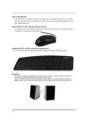
... description of speakers (optional). Connect the mouse to the PS/2 keyboard port or USB port on the back panel of the system. System Peripherals The EL1800 series computer consist of the system itself, and system peripherals, like a mouse, keyboard, card reader and a set of the basic system peripherals. Mouse (PS/2 or... two-button wheel mouse. Keyboard (PS/2 or USB, manufacturing option) Connect the keyboard to the PS/2 mouse port or USB port on the actual product. 10 NOTE: speakers are optional and the appearance might be different depending on the back panel of the system.
... description of speakers (optional). Connect the mouse to the PS/2 keyboard port or USB port on the back panel of the system. System Peripherals The EL1800 series computer consist of the system itself, and system peripherals, like a mouse, keyboard, card reader and a set of the basic system peripherals. Mouse (PS/2 or... two-button wheel mouse. Keyboard (PS/2 or USB, manufacturing option) Connect the keyboard to the PS/2 mouse port or USB port on the actual product. 10 NOTE: speakers are optional and the appearance might be different depending on the back panel of the system.

Service Guide
Page 19
... Support memory interface Support memory module package Support parity check feature Support to Error Correction Code (ECC) feature Memory module combinations Specification 2 slots 512MB to 10 ports 13 Video Interface Item Video controller Video controller resident bus Video Interface NV MCP73PV PCIE X16 Specification Audio Interface Item Audio controller Audio controller...
... Support memory interface Support memory module package Support parity check feature Support to Error Correction Code (ECC) feature Memory module combinations Specification 2 slots 512MB to 10 ports 13 Video Interface Item Video controller Video controller resident bus Video Interface NV MCP73PV PCIE X16 Specification Audio Interface Item Audio controller Audio controller...
Service Guide
Page 21
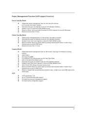
... for hard disk drive devices (0-15 minutes, time step=1 minute). Global Standby Mode z Global power management timer (2-120 minutes, time step=10 minute). z Return to original state by pushing external switch button, modem ring in and USB keyboard for APM mode. ACPI z ACPI specification... 1.0b. Suspend Mode z Independent power management timer (2-120 minutes, time step=10 minutes) or pushing external z switch button. z Resume recovery time: 7-10 sec. z Hard disk drive goes into power saving mode. z Disable H-sync and V-sync signals to control...
... for hard disk drive devices (0-15 minutes, time step=1 minute). Global Standby Mode z Global power management timer (2-120 minutes, time step=10 minute). z Return to original state by pushing external switch button, modem ring in and USB keyboard for APM mode. ACPI z ACPI specification... 1.0b. Suspend Mode z Independent power management timer (2-120 minutes, time step=10 minutes) or pushing external z switch button. z Resume recovery time: 7-10 sec. z Hard disk drive goes into power saving mode. z Disable H-sync and V-sync signals to control...
Service Guide
Page 25
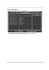
... Processor Type Intel ( R) Core( TM)2 Duo CPU E7200 Processor Speed 2.53 GHz System Memory 2048 MB System Manufacturer eMachines Product Name EL1800 System Serial Number Unknow System BIOS Version R01-A0 BIOS Release Date 10/24/2008 Asset Tag Number Unknow @ 2.53GHz Item Help Move Enter:Select +/-:Value F10:Save...
... Processor Type Intel ( R) Core( TM)2 Duo CPU E7200 Processor Speed 2.53 GHz System Memory 2048 MB System Manufacturer eMachines Product Name EL1800 System Serial Number Unknow System BIOS Version R01-A0 BIOS Release Date 10/24/2008 Asset Tag Number Unknow @ 2.53GHz Item Help Move Enter:Select +/-:Value F10:Save...
Service Guide
Page 56
... manual configured onboard peripherals, memory and I/O decode windows in APIC mode. 01, 02, 03, 04, 05 Entering sleep state S1, S2, S3, S4, or S5. 10, 20, 30, 40, 50 Waking from sleep state S1, S2, S3, S4, or S5. 50 It also assigns PCI bus numbers. Static resources are set...
... manual configured onboard peripherals, memory and I/O decode windows in APIC mode. 01, 02, 03, 04, 05 Entering sleep state S1, S2, S3, S4, or S5. 10, 20, 30, 40, 50 Waking from sleep state S1, S2, S3, S4, or S5. 50 It also assigns PCI bus numbers. Static resources are set...

Service Guide
Page 63
... Error Messages List" on page 64. Power off the system unit. 3. Check the power supply voltages. Perform the following checks, one by one at a time. 10. Load default settings in "or "Error Symptoms List" on the system unit. 12. Repeat steps 2 through 5 until you find the failing device or adapter. 57...
... Error Messages List" on page 64. Power off the system unit. 3. Check the power supply voltages. Perform the following checks, one by one at a time. 10. Load default settings in "or "Error Symptoms List" on the system unit. 12. Repeat steps 2 through 5 until you find the failing device or adapter. 57...

Service Guide
Page 68
ATX_POWER1:ATX 20-pin Power Connector Pin Signal Name 1 +3.3V 2 +3.3V 3 GND 4 +5V 5 GND 6 +5V 7 GND 8 Power Good 9 +5VSB 10 +12V Pin Signal Name 11 +12v 12 -12V 13 GND 14 Power ON 15 GND 16 GND 17 GND 18 NC 19 +5V 20 +5V ...
ATX_POWER1:ATX 20-pin Power Connector Pin Signal Name 1 +3.3V 2 +3.3V 3 GND 4 +5V 5 GND 6 +5V 7 GND 8 Power Good 9 +5VSB 10 +12V Pin Signal Name 11 +12v 12 -12V 13 GND 14 Power ON 15 GND 16 GND 17 GND 18 NC 19 +5V 20 +5V ...

Service Guide
Page 69
... Reserved 11 RSVD Reserved 13 RSVD Reserved *.MSG LED (dual color or single color) Pin Signal Name 2 FP PWR/SLP 4 FP PWR/SLP 6 PWR_SW_P 8 PWR_SW_N 10 Key 12 LAN LED 14 LAN LED Function *MSG LED(+) *MSG LED(-) Power Switch(+) Power Switch(-) No pin LAN LED (+) LAN LED (-) Hard Drive Activity...
... Reserved 11 RSVD Reserved 13 RSVD Reserved *.MSG LED (dual color or single color) Pin Signal Name 2 FP PWR/SLP 4 FP PWR/SLP 6 PWR_SW_P 8 PWR_SW_N 10 Key 12 LAN LED 14 LAN LED Function *MSG LED(+) *MSG LED(-) Power Switch(+) Power Switch(-) No pin LAN LED (+) LAN LED (-) Hard Drive Activity...

Service Guide
Page 78
... Serial ATA devices for easier access. Pin Signal Name 1 PORT 1L 3 PORT 1R 5 PORT 2R 7 SENSE_SEND 9 PORT 2L Pin Signal Name 2 AUD_GND 4 PRESENCE# 6 SENSE1_RETURN 8 KEY 10 SENSE2_RETURN SATA 1~2: Serial ATA connectors These connectors are used to install auxiliary front-oriented microphone and line-out ports for the highest date transfer rates...
... Serial ATA devices for easier access. Pin Signal Name 1 PORT 1L 3 PORT 1R 5 PORT 2R 7 SENSE_SEND 9 PORT 2L Pin Signal Name 2 AUD_GND 4 PRESENCE# 6 SENSE1_RETURN 8 KEY 10 SENSE2_RETURN SATA 1~2: Serial ATA connectors These connectors are used to install auxiliary front-oriented microphone and line-out ports for the highest date transfer rates...

Service Guide
Page 79
... through optical fiber or coaxial connector. Pin Signal Name 1 USBPWR 2 USBPWR 3 USB_FP_P0- 4 USB_FP_P1- 5 USB_FP_P0+ 6 USB_FP_P1+ 7 GND 8 GND 9 Key 10 NC Function Front Panel USB Power Front Panel USB Power USB Port0 Negative Signal USB Port1 Negative Signal USB Port0 Positive Signal USB Port1 Positive... Pin Signal Name 1 TPA+ 3 GND 5 TPB+ 7 Cable-Power 9 Key pin Pin Signal Name 2 TPA- 4 GND 6 TPB- 8 Cable-Power 10 GND 73 A different pin assignment may cause damage or system hang-up. F_USB1~3: Front Panel USB headers The motherboard has four USB ports installed on...
... through optical fiber or coaxial connector. Pin Signal Name 1 USBPWR 2 USBPWR 3 USB_FP_P0- 4 USB_FP_P1- 5 USB_FP_P0+ 6 USB_FP_P1+ 7 GND 8 GND 9 Key 10 NC Function Front Panel USB Power Front Panel USB Power USB Port0 Negative Signal USB Port1 Negative Signal USB Port0 Positive Signal USB Port1 Positive... Pin Signal Name 1 TPA+ 3 GND 5 TPB+ 7 Cable-Power 9 Key pin Pin Signal Name 2 TPA- 4 GND 6 TPB- 8 Cable-Power 10 GND 73 A different pin assignment may cause damage or system hang-up. F_USB1~3: Front Panel USB headers The motherboard has four USB ports installed on...

