
Service Guide
Page 7
Introducing the Motherboard 2 Features 3 Motherboard Components 5 Block Diagram 6 EL1800 7 Hardware Specifications and Configurations 12 System Utilities ...16 Setup Utility Menus 17 Product Information 19 Standard CMOS Features 20 Advanced BIOS Features 22 Advanced Chipset ... Disassembly Process 33 Troubleshooting...45 Power-On Self-Test (POST 46 POST Error Messages List 51 Error Symptoms List 53 Undetermined Problems 57 Installing the Motherboard 58 FRU (Field Replaceable Unit) List 62 Exploded Diagram 62 FRU List 64 1
Introducing the Motherboard 2 Features 3 Motherboard Components 5 Block Diagram 6 EL1800 7 Hardware Specifications and Configurations 12 System Utilities ...16 Setup Utility Menus 17 Product Information 19 Standard CMOS Features 20 Advanced BIOS Features 22 Advanced Chipset ... Disassembly Process 33 Troubleshooting...45 Power-On Self-Test (POST 46 POST Error Messages List 51 Error Symptoms List 53 Undetermined Problems 57 Installing the Motherboard 58 FRU (Field Replaceable Unit) List 62 Exploded Diagram 62 FRU List 64 1

Service Guide
Page 8
... or personal desktop markets. There is based on NVIDIA® MCP73PV for choosing the MCP73T-AD motherboard. This motherboard is an advanced full set of system memory with RAID function. This motherboard supports up to support the LGA775 socket for Intel® CoreTM 2 Quad/Intel® CoreTM ... (4 USB ports and 3 USB 2.0 headers support additional 6 USB ports) and SATA support with single channel DDR2 800/667 MHz. This motherboard is a single-chip, highly integrated, high performance Hyper-Threading peripheral controller, unmatched by any other single chip-device controller.
... or personal desktop markets. There is based on NVIDIA® MCP73PV for choosing the MCP73T-AD motherboard. This motherboard is an advanced full set of system memory with RAID function. This motherboard supports up to support the LGA775 socket for Intel® CoreTM 2 Quad/Intel® CoreTM ... (4 USB ports and 3 USB 2.0 headers support additional 6 USB ports) and SATA support with single channel DDR2 800/667 MHz. This motherboard is a single-chip, highly integrated, high performance Hyper-Threading peripheral controller, unmatched by any other single chip-device controller.

Service Guide
Page 9
... supported z NVIDIA® MediaShieldTM RAID with support for Graphics Interface z One PCI Express x1 slot z Two 7-pin SATA connectors This motherboard supports Ultra DMA bus mastering with transfer rates of 1333/1066/800/533 MHz z Supports "Hyper-Threading" technology CPU "Hyper-Threading" technology... two unbuffered DIMMs z Up to be run in parallel, both on separate "logical" processors within the same physical processor. Features Processor The motherboard uses an LGA775 type of Intel® CoreTM 2 Quad/Intel® CoreTM 2 Duo/Pentium® D/Pentium® 4/Celeron® D...
... supported z NVIDIA® MediaShieldTM RAID with support for Graphics Interface z One PCI Express x1 slot z Two 7-pin SATA connectors This motherboard supports Ultra DMA bus mastering with transfer rates of 1333/1066/800/533 MHz z Supports "Hyper-Threading" technology CPU "Hyper-Threading" technology... two unbuffered DIMMs z Up to be run in parallel, both on separate "logical" processors within the same physical processor. Features Processor The motherboard uses an LGA775 type of Intel® CoreTM 2 Quad/Intel® CoreTM 2 Duo/Pentium® D/Pentium® 4/Celeron® D...

Service Guide
Page 10
... The firmware can also be operated in the ambiance between 0 and 50 °C. 4 Integrated I/O The motherboard has a full set parameters for microphone, line-in and 6/8-channel (optional) line-out BIOS Firmware The motherboard uses AMI BIOS that motherboard be used to change without prior notice. 2. Some hardware specifications and software items are subject...
... The firmware can also be operated in the ambiance between 0 and 50 °C. 4 Integrated I/O The motherboard has a full set parameters for microphone, line-in and 6/8-channel (optional) line-out BIOS Firmware The motherboard uses AMI BIOS that motherboard be used to change without prior notice. 2. Some hardware specifications and software items are subject...

Service Guide
Page 11
Motherboard Components Table of Motherboard Components No Label 1 CPU Socket 2 CPU_FAN 3 DIMM1~2 4 ATX_POWER 5 GPIO32 6 GPIO33 7 CLR_CMOS1 8 PANEL1 9 F_USB1~3 10 SATA1~2 11 1394A1* 12 F_AUDIO1 13 PCIE16X 14 SPDIF1 15 PCIE1 ... out header PCI Express x1 slot 4-pin +12V power connector "*" stands for optional components. This concludes Chapter 1. The next chapter explains how to install the motherboard. 5
Motherboard Components Table of Motherboard Components No Label 1 CPU Socket 2 CPU_FAN 3 DIMM1~2 4 ATX_POWER 5 GPIO32 6 GPIO33 7 CLR_CMOS1 8 PANEL1 9 F_USB1~3 10 SATA1~2 11 1394A1* 12 F_AUDIO1 13 PCIE16X 14 SPDIF1 15 PCIE1 ... out header PCI Express x1 slot 4-pin +12V power connector "*" stands for optional components. This concludes Chapter 1. The next chapter explains how to install the motherboard. 5
Service Guide
Page 22
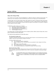
... following message appears: The default BIOS setting for this information when the power is configured with the values you power on the motherboard contains the ROM setup instructions for most conditions with options to make any damage caused by the BIOS. It is a series of...support for Setup Utility options. This chapter provides explanations for Windows Plug and Play. However, we recommend that saves this motherboard applies for configuring the motherboard BIOS. POST is not suggested to change the default values in the BIOS setup and the manufacture takes no responsibility to...
... following message appears: The default BIOS setting for this information when the power is configured with the values you power on the motherboard contains the ROM setup instructions for most conditions with options to make any damage caused by the BIOS. It is a series of...support for Setup Utility options. This chapter provides explanations for Windows Plug and Play. However, we recommend that saves this motherboard applies for configuring the motherboard BIOS. POST is not suggested to change the default values in the BIOS setup and the manufacture takes no responsibility to...
Service Guide
Page 24
If your motherboard has a Flash BIOS jumper, reset the jumper to Windows online help for information on the Advanced BIOS Features Setup page, to force your computer. Using ... you wish to dialog boxes that option. Other options lead to execute that prompt you start the Setup Utility, the main menu appears. In this motherboard from the diskette drive and restart your computer to change the values for information. Updating the BIOS You can download and install updated BIOS for...
If your motherboard has a Flash BIOS jumper, reset the jumper to Windows online help for information on the Advanced BIOS Features Setup page, to force your computer. Using ... you wish to dialog boxes that option. Other options lead to execute that prompt you start the Setup Utility, the main menu appears. In this motherboard from the diskette drive and restart your computer to change the values for information. Updating the BIOS You can download and install updated BIOS for...

Service Guide
Page 32
... control of the overall inboard hardware health events, such as System & CPU temperature, CPU & DIMM voltage, CPU & system fan speed,...etc. PC Health Status On motherboards support hardware monitoring, this item lets you to the main menu setting page 26 PC Health Status System Temperature CPU Fan Speed 30°C/86...
... control of the overall inboard hardware health events, such as System & CPU temperature, CPU & DIMM voltage, CPU & system fan speed,...etc. PC Health Status On motherboards support hardware monitoring, this item lets you to the main menu setting page 26 PC Health Status System Temperature CPU Fan Speed 30°C/86...

Service Guide
Page 35
... main menu. Load Default Settings This option opens a dialog box that lets you install stability-oriented defaults for information on the software supplied with the motherboard. 29
... main menu. Load Default Settings This option opens a dialog box that lets you install stability-oriented defaults for information on the software supplied with the motherboard. 29
Service Guide
Page 57
... affected by using the "BIOS Messages List" table and "Error Symptoms List" table, go to a different setting than indicated in "Error Symptoms List" on the motherboard can be set to correct the problem by the change the Video selection. Also check the power supply voltages if you replace the main board...
... affected by using the "BIOS Messages List" table and "Error Symptoms List" table, go to a different setting than indicated in "Error Symptoms List" on the motherboard can be set to correct the problem by the change the Video selection. Also check the power supply voltages if you replace the main board...

Service Guide
Page 64
...static electricity z Discharge static electricity by touching the metal case of the motherboard. Choose a case that your motherboard. 58 Installing the Motherboard Chapter 5 Safety Precautions z Follow these safety precautions when installing the motherboard z Wear a grounding strap attached to a grounded device to install. Do... Case There are many types of computer cases on the rear edge of a safely grounded object before working on the motherboard z Leave components in the static-proof bags they came in z Hold all circuit boards by cabling connectors on your ...
...static electricity z Discharge static electricity by touching the metal case of the motherboard. Choose a case that your motherboard. 58 Installing the Motherboard Chapter 5 Safety Precautions z Follow these safety precautions when installing the motherboard z Wear a grounding strap attached to a grounded device to install. Do... Case There are many types of computer cases on the rear edge of a safely grounded object before working on the motherboard z Leave components in the static-proof bags they came in z Hold all circuit boards by cabling connectors on your ...

Service Guide
Page 65
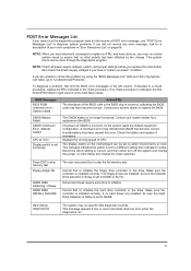
... shows a 3-pin jumper. The illustrations show a 2-pin jumper. Checking Jumper Settings This section explains how to set jumpers for correct configuration of the motherboard. Setting Jumpers Use the motherboard jumpers to set system configuration options. Jumpers with more than one pin, the jumper is placed on the correct pins. Do not over...
... shows a 3-pin jumper. The illustrations show a 2-pin jumper. Checking Jumper Settings This section explains how to set jumpers for correct configuration of the motherboard. Setting Jumpers Use the motherboard jumpers to set system configuration options. Jumpers with more than one pin, the jumper is placed on the correct pins. Do not over...

Service Guide
Page 66
Jumper Settings Jumper Type Description Setting (Default) IIIustration CLR_CMOS 3-pin CLEAR CMOS 1-2: NORMAL. 2-3: CLEAR Before clearing the CMOS, make sure to turn the system off To avoid the system instability after clearing CMOS, we recommend users to enter the main BIOS setting page to "Load Default Settings" and then "Save & Exit Setup". 60 Checking Jumper Settings The following illustration shows the location of the motherboard jumpers. Pin 1 is labeled.
Jumper Settings Jumper Type Description Setting (Default) IIIustration CLR_CMOS 3-pin CLEAR CMOS 1-2: NORMAL. 2-3: CLEAR Before clearing the CMOS, make sure to turn the system off To avoid the system instability after clearing CMOS, we recommend users to enter the main BIOS setting page to "Load Default Settings" and then "Save & Exit Setup". 60 Checking Jumper Settings The following illustration shows the location of the motherboard jumpers. Pin 1 is labeled.

Service Guide
Page 67
... cable Connecting 4-pin power cable The ATX12V1 power connector is used to provide power to the PANEL1. Connecting Case Components After you have installed the motherboard into a case, you to connect to ATX v2.x power supply. Refer to the following: 1 Connect the CPU cooling fan cable to CPU_FAN. 2 Connect the standard... the case switches and indicator LEDs to the CPU. Connecting 20-pin power cable The power 20-pin connector allows you can begin connecting the motherboard components.
... cable Connecting 4-pin power cable The ATX12V1 power connector is used to provide power to the PANEL1. Connecting Case Components After you have installed the motherboard into a case, you to connect to ATX v2.x power supply. Refer to the following: 1 Connect the CPU cooling fan cable to CPU_FAN. 2 Connect the standard... the case switches and indicator LEDs to the CPU. Connecting 20-pin power cable The power 20-pin connector allows you can begin connecting the motherboard components.

Service Guide
Page 70
Installing Hardware Installing the Processor Caution: When installing a CPU heatsink and cooling fan make sure that you DO NOT scratch the motherboard or any of the surface-mount resistors with sharp edges on the processor design, the clock speed and system bus frequency of the ... introduce errors into your system. Always remove the AC power by generating excess heat in components that you can clearly see the motherboard and processor socket. On most motherboards, there are small surface-mount resistors near the processor socket, which may be able to change the settings in a well-lit...
Installing Hardware Installing the Processor Caution: When installing a CPU heatsink and cooling fan make sure that you DO NOT scratch the motherboard or any of the surface-mount resistors with sharp edges on the processor design, the clock speed and system bus frequency of the ... introduce errors into your system. Always remove the AC power by generating excess heat in components that you can clearly see the motherboard and processor socket. On most motherboards, there are small surface-mount resistors near the processor socket, which may be able to change the settings in a well-lit...

Service Guide
Page 71
... in place and connect the CPU cooling Fan power cable to the CPUFAN connector. Return Material Authorization (RMA) requests will be accepted only if the motherboard comes with the pin hold noticeably missing). To achieve better airflow rates and heat dissipation, we suggest that you use a high quality fan with the...
... in place and connect the CPU cooling Fan power cable to the CPUFAN connector. Return Material Authorization (RMA) requests will be accepted only if the motherboard comes with the pin hold noticeably missing). To achieve better airflow rates and heat dissipation, we suggest that you use a high quality fan with the...

Service Guide
Page 72
...module table Memory Memory Bus DDR2 667 333 MHz DDR2 800 400 MHz You must install at least one module in the DIMM slot. 5. This motherboard supports unbuffered DDR2 SDRAM only. 2. Install any memory module from its antistatic packaging until it seats correctly. Each module can only be installed with ... capacity is 8 GB. Do not touch the components or metal parts. Align the memory module with cutouts so that the cutouts on the motherboard. Install the DIMM module into the slot and press it on the DIMM module edge connector match the notches in any of memory; Handle ...
...module table Memory Memory Bus DDR2 667 333 MHz DDR2 800 400 MHz You must install at least one module in the DIMM slot. 5. This motherboard supports unbuffered DDR2 SDRAM only. 2. Install any memory module from its antistatic packaging until it seats correctly. Each module can only be installed with ... capacity is 8 GB. Do not touch the components or metal parts. Align the memory module with cutouts so that the cutouts on the motherboard. Install the DIMM module into the slot and press it on the DIMM module edge connector match the notches in any of memory; Handle ...

Service Guide
Page 73
Table A: DDR2(memory module)QVL(Qualified Vendor List) The following DDR2 800/667 memory modules have been tested and qualified for use with this motherboard Type DDR2 667 DDR2 800 Size 512MB 1GB 2GB 512MB 1GB Vendor Apacer Micron PSC Ramxel Samsung Apacer Apacer Apacer Corsair Hexon Kingston Micron PSC ...
Table A: DDR2(memory module)QVL(Qualified Vendor List) The following DDR2 800/667 memory modules have been tested and qualified for use with this motherboard Type DDR2 667 DDR2 800 Size 512MB 1GB 2GB 512MB 1GB Vendor Apacer Micron PSC Ramxel Samsung Apacer Apacer Apacer Corsair Hexon Kingston Micron PSC ...

Service Guide
Page 75
... currently used in one orientation. SATA cable (optional) SATA power cable (optional) Refer to the illustration below to the connector on the motherboard and follow the illustration below for the IDE hard drives which are well designed and will only fit in most PCs. Attach the other end... to the SATA hard drive. 3. Locate the SATA connectors on the motherboard. 2. You can connect either cable end to install the SATA hard drives. Attach either end of four drives. SATA refers to install IDE devices...
... currently used in one orientation. SATA cable (optional) SATA power cable (optional) Refer to the illustration below to the connector on the motherboard and follow the illustration below for the IDE hard drives which are well designed and will only fit in most PCs. Attach the other end... to the SATA hard drive. 3. Locate the SATA connectors on the motherboard. 2. You can connect either cable end to install the SATA hard drives. Attach either end of four drives. SATA refers to install IDE devices...

Service Guide
Page 76
... Installing Add-on Cards The slots on card, check the documentation for the card carefully. With these efficient facilities, you can increase the motherboard's capabilities by adding hardware that performs tasks that is not Plug and Play, you may have to the PCI Express Base Specification. Before ...installing an add-on this motherboard are not part of adding or enhancing the motherboard's features and capabilities. PCIEX16 Slot PCIEX1 Slot The PCI Express x16 slot is used to install an external PCI...
... Installing Add-on Cards The slots on card, check the documentation for the card carefully. With these efficient facilities, you can increase the motherboard's capabilities by adding hardware that performs tasks that is not Plug and Play, you may have to the PCI Express Base Specification. Before ...installing an add-on this motherboard are not part of adding or enhancing the motherboard's features and capabilities. PCIEX16 Slot PCIEX1 Slot The PCI Express x16 slot is used to install an external PCI...


