eMachines EL1358 Service Guide
Page 9
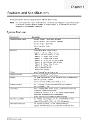
...Athlon II X2 270u and 260u, 25 watts - Sempron X2 180, 45 watts - The exact configuration of your PC depends on page 74 for GPU card installation) • One PCI Express x1 slot • Wired LAN: Realtek RTL8201EL (Single-Chip/Port 10/100/1000 Fast Ethernet PHYceiver with Auto MDIX) ...• WLAN option: Low-profile PCI-E x1 802.11 b/g/n wireless network adapter and Wireless 802.11b/g/n USB Adapter • Modem option: 56K Low Profile Dial-Up PCI-E Modem • One HDD bay suppporting 3.5-inch 25.4...
...Athlon II X2 270u and 260u, 25 watts - Sempron X2 180, 45 watts - The exact configuration of your PC depends on page 74 for GPU card installation) • One PCI Express x1 slot • Wired LAN: Realtek RTL8201EL (Single-Chip/Port 10/100/1000 Fast Ethernet PHYceiver with Auto MDIX) ...• WLAN option: Low-profile PCI-E x1 802.11 b/g/n wireless network adapter and Wireless 802.11b/g/n USB Adapter • Modem option: 56K Low Profile Dial-Up PCI-E Modem • One HDD bay suppporting 3.5-inch 25.4...
eMachines EL1358 Service Guide
Page 29
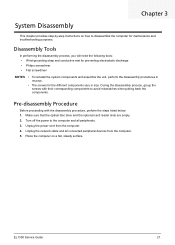
...Place the computer on how to avoid mismatches when putting back the components. Make sure that the optical disc drive and the optional card reader slots are empty. 2. Unplug the power cord from the computer. 5. During the disassembly process, group the screws with the... disassembly procedure, perform the steps listed below: 1. Unplug the network cable and all peripherals. 3. Chapter 3 System Disassembly This chapter provides step-by-step instructions on a flat, steady surface. Turn off the ...
...Place the computer on how to avoid mismatches when putting back the components. Make sure that the optical disc drive and the optional card reader slots are empty. 2. Unplug the power cord from the computer. 5. During the disassembly process, group the screws with the... disassembly procedure, perform the steps listed below: 1. Unplug the network cable and all peripherals. 3. Chapter 3 System Disassembly This chapter provides step-by-step instructions on a flat, steady surface. Turn off the ...
eMachines EL1358 Service Guide
Page 50
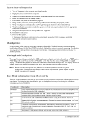
...Initialization Code Checkpoints The boot block initialization code sets up from the computer. 3. Verify that flat mode is available. Unplug the network cable and all power and data cables are firmly and properly attached to vendor requirements, system chipset or option ROMs from the computer... currently executing. Perform keyboard controller BAT test. If memory sizing module not executed, start memory refresh and do memory sizing in cards that all components are firmly and properly attached to as described in page 22. 6. System Internal Inspection 1. Test base 512 KB...
...Initialization Code Checkpoints The boot block initialization code sets up from the computer. 3. Verify that flat mode is available. Unplug the network cable and all power and data cables are firmly and properly attached to vendor requirements, system chipset or option ROMs from the computer... currently executing. Perform keyboard controller BAT test. If memory sizing module not executed, start memory refresh and do memory sizing in cards that all components are firmly and properly attached to as described in page 22. 6. System Internal Inspection 1. Test base 512 KB...
eMachines EL1358 Service Guide
Page 70
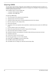
... block and set it over the 2-3 pins for 20 to the system. 13. Connect the AC power cord to 30 seconds. 9. Unplug the network cable and all peripherals. 2. Press the power button to turn on a flat, steady surface. 5. Press F10 to save the changes you made .... Use the JBIOS1 jumper to its default 1-2 position. 10. If necessary, remove any expansion card, peripheral, and system cables that prevent access to the CMOS clear jumper. 7. Reinstall any expansion cards, assemblies or cables that have previously been removed. 11. Return the jumper block to clear the...
... block and set it over the 2-3 pins for 20 to the system. 13. Connect the AC power cord to 30 seconds. 9. Unplug the network cable and all peripherals. 2. Press the power button to turn on a flat, steady surface. 5. Press F10 to save the changes you made .... Use the JBIOS1 jumper to its default 1-2 position. 10. If necessary, remove any expansion card, peripheral, and system cables that prevent access to the CMOS clear jumper. 7. Reinstall any expansion cards, assemblies or cables that have previously been removed. 11. Return the jumper block to clear the...


