
Service Guide
Page 65
.... 2. Chapter 3 55 The use of the computer. Insert a suitable plastic tool (or finger) and pry the Switch Cover upward, away from the Upper Cover. 3. Work along the Switch Cover toward the left hinge, gently prying up the cover as shown. 4. See "Removing the Battery Pack" on the right side of the Keyboard to the outer...
.... 2. Chapter 3 55 The use of the computer. Insert a suitable plastic tool (or finger) and pry the Switch Cover upward, away from the Upper Cover. 3. Work along the Switch Cover toward the left hinge, gently prying up the cover as shown. 4. See "Removing the Battery Pack" on the right side of the Keyboard to the outer...
Service Guide
Page 69
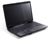
Remove the black Antenna cable from the cable channel as shown, and lift to the hinge well. 9. 7. Open the LCD Panel to the full extent to the Upper Cover. 8. Remove the adhesive tape securing the Antenna cable to expose the Hinge Covers. 10. Chapter 3 59 Ensure that the cable is completely free of the retaining clips all the way to remove the cover from the chassis. 11. Repeat the process for the right side Hinge Cover. Press the left side Hinge Cover inward, as shown.
Remove the black Antenna cable from the cable channel as shown, and lift to the hinge well. 9. 7. Open the LCD Panel to the full extent to the Upper Cover. 8. Remove the adhesive tape securing the Antenna cable to expose the Hinge Covers. 10. Chapter 3 59 Ensure that the cable is completely free of the retaining clips all the way to remove the cover from the chassis. 11. Repeat the process for the right side Hinge Cover. Press the left side Hinge Cover inward, as shown.

Service Guide
Page 70
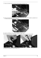
Remove the four securing screws (two each side) from on top of the Upper Cover. 60 Chapter 3 Lift the LCD Module clear of the hinges Screw Type 14. Remove the left and right screw covers from the LCD module. 12. Step LCD Module Size M2.5*8 Quantity 4 13.
Remove the four securing screws (two each side) from on top of the Upper Cover. 60 Chapter 3 Lift the LCD Module clear of the hinges Screw Type 14. Remove the left and right screw covers from the LCD module. 12. Step LCD Module Size M2.5*8 Quantity 4 13.
Service Guide
Page 119
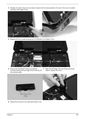
Ensure that the securing tab on the rear of the covers by the down to the Upper Cover. 6. Align the left Hinge Cover as shown. Replace the four screws securing the LCD Module to replace the cover. Identify the rear edge of the cover is seated correctly in the Upper Cover. 5. two securing clips. Repeat the process for the right side Hinge Cover. Replace the right screw cover as shown and press correctly. Chapter 3 109 Ensure that the Hinge Covers are replaced 7. Rear Securing Clips 8. 4.
Ensure that the securing tab on the rear of the covers by the down to the Upper Cover. 6. Align the left Hinge Cover as shown. Replace the four screws securing the LCD Module to replace the cover. Identify the rear edge of the cover is seated correctly in the Upper Cover. 5. two securing clips. Repeat the process for the right side Hinge Cover. Replace the right screw cover as shown and press correctly. Chapter 3 109 Ensure that the Hinge Covers are replaced 7. Rear Securing Clips 8. 4.

Service Guide
Page 157
No. Description 1 Middle Cover Assy 2 Hinge Cap Assy 3 Upper Case Assy 4 Mainboard 5 Lower Case Acer P/N 60.N2802.003 42.N2802.001 60.N2802.001 MB.N6502.001 60.N2802.002 Chapter 6 147
No. Description 1 Middle Cover Assy 2 Hinge Cap Assy 3 Upper Case Assy 4 Mainboard 5 Lower Case Acer P/N 60.N2802.003 42.N2802.001 60.N2802.001 MB.N6502.001 60.N2802.002 Chapter 6 147

Service Guide
Page 161
CATEGORY LOWER CASE Description TP BRACKET MIDDLE COVER ASSY HINGE CAP ASSY UP CAP R UP CAP L RAM DOOR ASSY HDD DOOR ASSY AcerPN 60.N2802.002 33.N2802.001 60.N2802.003 42.N2802.001 42.N2802.002 42.N2802.003 42.N2802.004 42.N2802.005 Chapter 6 151
CATEGORY LOWER CASE Description TP BRACKET MIDDLE COVER ASSY HINGE CAP ASSY UP CAP R UP CAP L RAM DOOR ASSY HDD DOOR ASSY AcerPN 60.N2802.002 33.N2802.001 60.N2802.003 42.N2802.001 42.N2802.002 42.N2802.003 42.N2802.004 42.N2802.005 Chapter 6 151


