
User Guide
Page 10
Table of Contents 3.1.5 Procedure to Turn on the Switch Power 36 3.1.6 Power Connector (AC 36 3.1.7 Signal Slot ...36 3.2 LEDs ...38 Part II: Technical Reference 41 Chapter 4 The Web Configurator ...43 4.1 Introduction ...43 4.2 System Login ...43 4.3 The Status Screen ...44 4.3.1 Change Your Password 49 4.4 Saving ... 6.2.3 Configuring DHCP Relay 67 6.2.4 Troubleshooting ...68 Chapter 7 System Status and Port Statistics 69 7.1 Overview ...69 7.2 Port Status Summary ...70 7.2.1 Status: Port Details 71 10 MES-3528 User's Guide
Table of Contents 3.1.5 Procedure to Turn on the Switch Power 36 3.1.6 Power Connector (AC 36 3.1.7 Signal Slot ...36 3.2 LEDs ...38 Part II: Technical Reference 41 Chapter 4 The Web Configurator ...43 4.1 Introduction ...43 4.2 System Login ...43 4.3 The Status Screen ...44 4.3.1 Change Your Password 49 4.4 Saving ... 6.2.3 Configuring DHCP Relay 67 6.2.4 Troubleshooting ...68 Chapter 7 System Status and Port Statistics 69 7.1 Overview ...69 7.2 Port Status Summary ...70 7.2.1 Status: Port Details 71 10 MES-3528 User's Guide
User Guide
Page 17
... ...319 38.2 Viewing the ARP Table ...320 Chapter 39 Configure Clone...321 39.1 Configure Clone ...321 Chapter 40 Troubleshooting...323 40.1 Power, Hardware Connections, and LEDs 323 40.2 Switch Access and Login 324 40.3 Switch Configuration ...326 Chapter 41 Product Specifications ...327 Appendix A Changing a Fuse 335 Appendix B Common Services 337 MES...
... ...319 38.2 Viewing the ARP Table ...320 Chapter 39 Configure Clone...321 39.1 Configure Clone ...321 Chapter 40 Troubleshooting...323 40.1 Power, Hardware Connections, and LEDs 323 40.2 Switch Access and Login 324 40.3 Switch Configuration ...326 Chapter 41 Product Specifications ...327 Appendix A Changing a Fuse 335 Appendix B Common Services 337 MES...
User Guide
Page 31
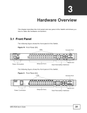
Figure 10 Front Panel (DC) LEDs Console Port Power Connection Ethernet Ports Signal slot Dual Personality Interfaces The following figure shows the front panel of the Switch. Figure 11 Front Panel (AC) LEDs Console Port Power Connection Ethernet Ports Signal slot Dual Personality Interfaces MES-3528 User's Guide 31 CHAPTER 3 Hardware Overview This chapter describes the front panel and rear panel of the Switch and shows you how to make the hardware connections. 3.1 Front Panel The following figure shows the front panel of the Switch.
Figure 10 Front Panel (DC) LEDs Console Port Power Connection Ethernet Ports Signal slot Dual Personality Interfaces The following figure shows the front panel of the Switch. Figure 11 Front Panel (AC) LEDs Console Port Power Connection Ethernet Ports Signal slot Dual Personality Interfaces MES-3528 User's Guide 31 CHAPTER 3 Hardware Overview This chapter describes the front panel and rear panel of the Switch and shows you how to make the hardware connections. 3.1 Front Panel The following figure shows the front panel of the Switch.
User Guide
Page 34
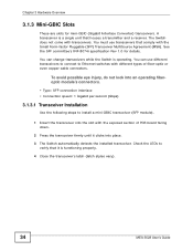
...transmitter and a receiver. You can use transceivers that it clicks into place. 3 The Switch automatically detects the installed transceiver. Check the LEDs to verify that comply with different types of PCB board facing down. 2 Press the transceiver firmly until it is functioning properly. 4 Close... the transceiver's latch (latch styles vary). 34 MES-3528 User's Guide Chapter 3 Hardware Overview 3.1.3 Mini-GBIC Slots These are slots for details. You must use different transceivers to connect to ...
...transmitter and a receiver. You can use transceivers that it clicks into place. 3 The Switch automatically detects the installed transceiver. Check the LEDs to verify that comply with different types of PCB board facing down. 2 Press the transceiver firmly until it is functioning properly. 4 Close... the transceiver's latch (latch styles vary). 34 MES-3528 User's Guide Chapter 3 Hardware Overview 3.1.3 Mini-GBIC Slots These are slots for details. You must use different transceivers to connect to ...
User Guide
Page 38
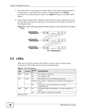
...off or the system is not ready/ malfunctioning. The power is functioning normally. 38 MES-3528 User's Guide Chapter 3 Hardware Overview 1 Use wires of the correct gauge to connect either...3-normal open) on the Signal connector to the input signal pin pairs of an Signal connector on another ZyXEL Switch. 2 When daisy-chaining further Switches ensure that the signal output pins you use are the same ...as those you connect the power to the Switch, view the LEDs to ensure proper functioning of the Same Model 3.2 LEDs After you used when connecting to Other Switches of the Switch and ...
...off or the system is not ready/ malfunctioning. The power is functioning normally. 38 MES-3528 User's Guide Chapter 3 Hardware Overview 1 Use wires of the correct gauge to connect either...3-normal open) on the Signal connector to the input signal pin pairs of an Signal connector on another ZyXEL Switch. 2 When daisy-chaining further Switches ensure that the signal output pins you use are the same ...as those you connect the power to the Switch, view the LEDs to ensure proper functioning of the Same Model 3.2 LEDs After you used when connecting to Other Switches of the Switch and ...
User Guide
Page 39
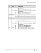
... Blinking The system is transmitting/receiving to this port is up . Off The Gigabit port is negotiating in full-duplex mode. MES-3528 User's Guide 39 On The link to a 10 Mbps or a 1000 Mbps Ethernet network is up . On The link to ...Dual Personality Interface) LNK/ACT Green Blinking The system is transmitting/receiving to /from a 10 Mbps Ethernet network. Chapter 3 Hardware Overview Table 2 LED Descriptions (continued) LED COLOR STATU S DESCRIPTION 1 ~ 24 Green Blinking The system is transmitting/receiving to /from a 10 Mbps or a 1000 Mbps Ethernet network. ...
... Blinking The system is transmitting/receiving to this port is up . Off The Gigabit port is negotiating in full-duplex mode. MES-3528 User's Guide 39 On The link to a 10 Mbps or a 1000 Mbps Ethernet network is up . On The link to ...Dual Personality Interface) LNK/ACT Green Blinking The system is transmitting/receiving to /from a 10 Mbps Ethernet network. Chapter 3 Hardware Overview Table 2 LED Descriptions (continued) LED COLOR STATU S DESCRIPTION 1 ~ 24 Green Blinking The system is transmitting/receiving to /from a 10 Mbps or a 1000 Mbps Ethernet network. ...
User Guide
Page 323
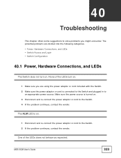
...following categories. • Power, Hardware Connections, and LEDs • Switch Access and Login • Switch Configuration 40.1 Power, Hardware Connections, and LEDs The Switch does not turn on . None of the LEDs does not behave as expected. The ALM LED is connected to the Switch and plugged in to ...3 Disconnect and re-connect the power adaptor or cord to the Switch. 2 If the problem continues, contact the vendor. One of the LEDs turn on . 1 Make sure you might encounter. CHAPTER 40 Troubleshooting This chapter offers some suggestions to an appropriate power source. MES...
...following categories. • Power, Hardware Connections, and LEDs • Switch Access and Login • Switch Configuration 40.1 Power, Hardware Connections, and LEDs The Switch does not turn on . None of the LEDs does not behave as expected. The ALM LED is connected to the Switch and plugged in to ...3 Disconnect and re-connect the power adaptor or cord to the Switch. 2 If the problem continues, contact the vendor. One of the LEDs turn on . 1 Make sure you might encounter. CHAPTER 40 Troubleshooting This chapter offers some suggestions to an appropriate power source. MES...
User Guide
Page 324
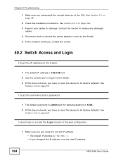
... username and/or password. 1 The default username is admin and the default password is 192.168.1.1. • If you understand the normal behavior of the LED. See Section 40.1 on page 50. Chapter 40 Troubleshooting 1 Make sure you changed the IP address, use the new IP address. 324 MES...
... username and/or password. 1 The default username is admin and the default password is 192.168.1.1. • If you understand the normal behavior of the LED. See Section 40.1 on page 50. Chapter 40 Troubleshooting 1 Make sure you changed the IP address, use the new IP address. 324 MES...
User Guide
Page 325
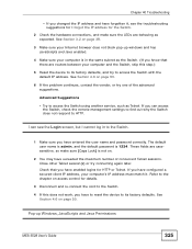
... respond to its factory defaults, and try to access the Switch using another service, such as expected. These fields are casesensitive, so make sure the LEDs are routers between your Internet browser does not block pop-up Windows, JavaScripts and Java Permissions MES...
... respond to its factory defaults, and try to access the Switch using another service, such as expected. These fields are casesensitive, so make sure the LEDs are routers between your Internet browser does not block pop-up Windows, JavaScripts and Java Permissions MES...
User Guide
Page 327
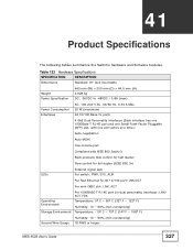
... Auto-MDIX One console port Compliant with IEEE 802.3ad/u/x Back pressure flow control for half duplex Flow control for full duplex (IEEE 802.3x) LEDs External signal jack Per switch: PWR, SYS, ALM Per Fast Ethernet RJ-45 10/100 port: LNK/ACT Per mini-GBIC slot: LNK, ACT Operating... ~ 90% (non-condensing) Temperature: -10º C ~ 70º C (14º F ~ 158º F) Ground Wire Gauge Humidity: 10 ~ 90% (non-condensing) 18 AWG or larger MES-3528 User's Guide 327 CHAPTER 41 Product Specifications The following tables summarize the Switch's hardware and firmware features.
... Auto-MDIX One console port Compliant with IEEE 802.3ad/u/x Back pressure flow control for half duplex Flow control for full duplex (IEEE 802.3x) LEDs External signal jack Per switch: PWR, SYS, ALM Per Fast Ethernet RJ-45 10/100 port: LNK/ACT Per mini-GBIC slot: LNK, ACT Operating... ~ 90% (non-condensing) Temperature: -10º C ~ 70º C (14º F ~ 158º F) Ground Wire Gauge Humidity: 10 ~ 90% (non-condensing) 18 AWG or larger MES-3528 User's Guide 327 CHAPTER 41 Product Specifications The following tables summarize the Switch's hardware and firmware features.
User Guide
Page 348
... 242 UDLD 241 VTP 241 LACP 147, 244 system priority 154 timeout 154 layer 2 features 330 Layer 2 protocol tunneling, see L2PT layer 3 features 331 LEDs 38 limit MAC address learning 163 link aggregation 147 dynamic 147 ID information 148 setup 151, 153 status 149 traffic distribution algorithm 150 traffic distribution... login password 292 loop guard 237 examples 238 port shut down 239 setup 239 vs. See FTP. 25 using FTP. See command interface. 25 MES-3528 User's Guide STP 237 M MAC (Media Access Control) 76 MAC address 76, 319 maximum number per port 163 MAC address learning 98, 101, 107,...
... 242 UDLD 241 VTP 241 LACP 147, 244 system priority 154 timeout 154 layer 2 features 330 Layer 2 protocol tunneling, see L2PT layer 3 features 331 LEDs 38 limit MAC address learning 163 link aggregation 147 dynamic 147 ID information 148 setup 151, 153 status 149 traffic distribution algorithm 150 traffic distribution... login password 292 loop guard 237 examples 238 port shut down 239 setup 239 vs. See FTP. 25 using FTP. See command interface. 25 MES-3528 User's Guide STP 237 M MAC (Media Access Control) 76 MAC address 76, 319 maximum number per port 163 MAC address learning 98, 101, 107,...

