

User Guide
Page 5
... ports 24 10/100/1000Base-T Ethernet ports 2 100/1000Base-X SFP slots One physical IEEE 802.3az ON/OFF button One power ON/OFF switch GS1100-24 GS1100-24E The GS1100-8HP has four GbE PoE ports that offers low latency for 100Mbps or 1Gbps connections to Know Your Switch 1.1 Introduction This chapter describes the key...
... ports 24 10/100/1000Base-T Ethernet ports 2 100/1000Base-X SFP slots One physical IEEE 802.3az ON/OFF button One power ON/OFF switch GS1100-24 GS1100-24E The GS1100-8HP has four GbE PoE ports that offers low latency for 100Mbps or 1Gbps connections to Know Your Switch 1.1 Introduction This chapter describes the key...

User Guide
Page 6
...Supports automatic address learning. • Supports IEEE 802.3az EEE • Supports IEEE 802.3af and IEEE 802.3at PoE standards (only GS1100-8HP) • Full wire speed forwarding rate. • Supports 802.1p CoS. • Embedded 8K MAC address table providing 8000 MAC ... Applications This section provides two network topology examples in which the Switch is used. 6 GS1100 Series User's Guide Chapter 1 Getting to Know Your Switch Figure 1 Front Panel GS1100-8HP GS1100-16 GS1100-24 GS1100-24E 1.2 Features The following are the essential features of the Switch. • Conforms to IEEE...
...Supports automatic address learning. • Supports IEEE 802.3az EEE • Supports IEEE 802.3af and IEEE 802.3at PoE standards (only GS1100-8HP) • Full wire speed forwarding rate. • Supports 802.1p CoS. • Embedded 8K MAC address table providing 8000 MAC ... Applications This section provides two network topology examples in which the Switch is used. 6 GS1100 Series User's Guide Chapter 1 Getting to Know Your Switch Figure 1 Front Panel GS1100-8HP GS1100-16 GS1100-24 GS1100-24E 1.2 Features The following are the essential features of the Switch. • Conforms to IEEE...

User Guide
Page 9
... the supplied power cord or power adaptor to the power receptacle on or off. 2.2 Front Panel The front panel of the Switch. For the GS1100-8HP, GS1100-16 and GS1100-24E, use the POWER ON/OFF switch to have the Switch power on the back of the Switch and the other end to the power...
... the supplied power cord or power adaptor to the power receptacle on or off. 2.2 Front Panel The front panel of the Switch. For the GS1100-8HP, GS1100-16 and GS1100-24E, use the POWER ON/OFF switch to have the Switch power on the back of the Switch and the other end to the power...

User Guide
Page 13
... to the PoE port(s) is on the Switch. Figure 11 Front Panel LEDs GS1100-8HP GS1100-16 GS1100-24 GS1100-24E Chapter 2 Hardware Description and Connection The following table describes the LEDs. GS1100 Series User's Guide 13 Table 3 The Front Panel LED Descriptions: GS1100-8HP LED COLOR STATUS DESCRIPTION PWR Green On The Switch is below the power budget...
... to the PoE port(s) is on the Switch. Figure 11 Front Panel LEDs GS1100-8HP GS1100-16 GS1100-24 GS1100-24E Chapter 2 Hardware Description and Connection The following table describes the LEDs. GS1100 Series User's Guide 13 Table 3 The Front Panel LED Descriptions: GS1100-8HP LED COLOR STATUS DESCRIPTION PWR Green On The Switch is below the power budget...
User Guide
Page 14
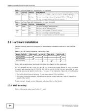
... The port is not receiving power. Off The Switch is receiving or transmitting data at 10M or 100M speed. For GS1100-16, GS1100-24 and GS110-24E, the size is not connected to an Ethernet network. 2.3 Hardware Installation See the following : • The Switch ...For GS1100-8HP, GS1100-16 and GS110-24E, you can place the Switch directly on and receiving power. Off The port is able to support the weight of each GS1100 model: Table 5 GS1100 Series Installation Comparison Table MODEL FEATURE Desktop Device Wall-mountable Rack-mountable GS1100-8HP GS1100-16 GS1100-24 GS1100-24E ...
... The port is not receiving power. Off The Switch is receiving or transmitting data at 10M or 100M speed. For GS1100-16, GS1100-24 and GS110-24E, the size is not connected to an Ethernet network. 2.3 Hardware Installation See the following : • The Switch ...For GS1100-8HP, GS1100-16 and GS110-24E, you can place the Switch directly on and receiving power. Off The port is able to support the weight of each GS1100 model: Table 5 GS1100 Series Installation Comparison Table MODEL FEATURE Desktop Device Wall-mountable Rack-mountable GS1100-8HP GS1100-16 GS1100-24 GS1100-24E ...
User Guide
Page 15
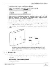
... slots and the connection cables to hold the weight of the Switch with the connection cables. 2 Align the holes on the back of the Switch. GS1100 Series User's Guide 15 Use screws with other equipment. The Switch should not be facing up or down the back of the Switch with your... in step 2). Follow the steps below to place the screws. Table 6 Distance between the head of the holes for wall mounting MODEL GS1100-8HP GS1100-16 DISTANCE 120 mm 148 mm GS1100-24E 207 mm 1 Screw the two screws provided with the screws on the screws. Do not screw the screws all the way in...
... slots and the connection cables to hold the weight of the Switch with the connection cables. 2 Align the holes on the back of the Switch. GS1100 Series User's Guide 15 Use screws with other equipment. The Switch should not be facing up or down the back of the Switch with your... in step 2). Follow the steps below to place the screws. Table 6 Distance between the head of the holes for wall mounting MODEL GS1100-8HP GS1100-16 DISTANCE 120 mm 148 mm GS1100-24E 207 mm 1 Screw the two screws provided with the screws on the screws. Do not screw the screws all the way in...

User Guide
Page 16
... two screw holes on the bracket with the screw holes on the side of the rack. 16 GS1100 Series User's Guide Figure 12 Attaching the Mounting Brackets (GS1100-16 and GS1100-24E) Figure 13 Attaching the Mounting Brackets (GS1100-24) 2 Using a #2 Philips screwdriver, install the M3 flat head screws through the mounting bracket holes into...
... two screw holes on the bracket with the screw holes on the side of the rack. 16 GS1100 Series User's Guide Figure 12 Attaching the Mounting Brackets (GS1100-16 and GS1100-24E) Figure 13 Attaching the Mounting Brackets (GS1100-24) 2 Using a #2 Philips screwdriver, install the M3 flat head screws through the mounting bracket holes into...

User Guide
Page 17
GS1100 Series User's Guide 17 Chapter 2 Hardware Description and Connection Figure 14 Mounting the Switch on a Rack (GS1100-16 and GS1100-24E) Figure 15 Mounting the Switch on a Rack (GS1100-24) 2 Using a #2 Philips screwdriver, install the M5 flat head screws through the mounting bracket holes into the rack. 3 Repeat steps 1 and 2 to attach the second mounting bracket on the other side of the rack.
GS1100 Series User's Guide 17 Chapter 2 Hardware Description and Connection Figure 14 Mounting the Switch on a Rack (GS1100-16 and GS1100-24E) Figure 15 Mounting the Switch on a Rack (GS1100-24) 2 Using a #2 Philips screwdriver, install the M5 flat head screws through the mounting bracket holes into the rack. 3 Repeat steps 1 and 2 to attach the second mounting bracket on the other side of the rack.