User Guide
Page 1
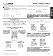
...Example 2 - Entry Switch - Heath®/Zenith wireless lighting controls are designed to work together. CODE SETTINGS Note: Most single system installations will work on the same principle and use the same code setting information. Receiver(s) Code Transmitter Code Example 1 - Add-A-Switch - Transmitter(s)/ Receiver(s) Code Transmitter(s)/ Receiver(s) Code Receiver(s) Code Remote Motion Sensor Code Group "A" Group "B" ( - wSeireeleTsrosupbroledsuhcOotsoN(tii.neg. ENGLISH Remote Controlled Products This manual includes operating instructions for a variety of...
...Example 2 - Entry Switch - Heath®/Zenith wireless lighting controls are designed to work together. CODE SETTINGS Note: Most single system installations will work on the same principle and use the same code setting information. Receiver(s) Code Transmitter Code Example 1 - Add-A-Switch - Transmitter(s)/ Receiver(s) Code Transmitter(s)/ Receiver(s) Code Receiver(s) Code Remote Motion Sensor Code Group "A" Group "B" ( - wSeireeleTsrosupbroledsuhcOotsoN(tii.neg. ENGLISH Remote Controlled Products This manual includes operating instructions for a variety of...
User Guide
Page 2
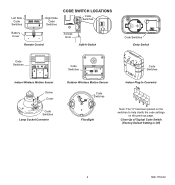
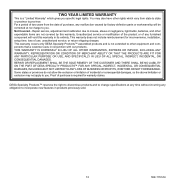
... Code Switches ON DIP 1 234 ON DIP 1 234 Right Side Code Switches Battery Cover Remote Control CODE SWITCH LOCATIONS DIM DIM Code ON 12 34 Switches ON 12 34 3V Li thium Bat 2032 tery tery Access Door thium Bat 2032 Add-A-Switch 3V Li CR2032 3 VOLTS ON 1 2 34 Code Switches Entry Switch Code Switches CODE ON DETECT ON-TIME RANGE (MINUTES) DAY NIGHT 1 2 3 4 NIGHT ONLY 5 1 TEST MIN MAX Indoor Wireless Motion Sensor Screw Cover Code Switches Lamp Socket...
... Code Switches ON DIP 1 234 ON DIP 1 234 Right Side Code Switches Battery Cover Remote Control CODE SWITCH LOCATIONS DIM DIM Code ON 12 34 Switches ON 12 34 3V Li thium Bat 2032 tery tery Access Door thium Bat 2032 Add-A-Switch 3V Li CR2032 3 VOLTS ON 1 2 34 Code Switches Entry Switch Code Switches CODE ON DETECT ON-TIME RANGE (MINUTES) DAY NIGHT 1 2 3 4 NIGHT ONLY 5 1 TEST MIN MAX Indoor Wireless Motion Sensor Screw Cover Code Switches Lamp Socket...
User Guide
Page 3
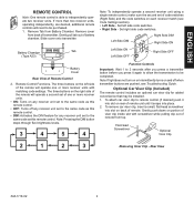
... ON: Turns on any receiver unit set to the same code as this remote control. • OFF: Turns off when transmitter buttons are desired, additional remote controls will operate a second set of code switches (Right Side) and the code switches on each receiver match (see Troubleshooting Guide. Set right side code switches. The three...purchased. 1. The three buttons on the left side code switches. • Right Side - Gently push down on rear of the remote will need to be installed. 1. ENGLISH REMOTE CONTROL Note: One remote control is able to 2 seconds after you press a ...
... ON: Turns on any receiver unit set to the same code as this remote control. • OFF: Turns off when transmitter buttons are desired, additional remote controls will operate a second set of code switches (Right Side) and the code switches on each receiver match (see Troubleshooting Guide. Set right side code switches. The three...purchased. 1. The three buttons on the left side code switches. • Right Side - Gently push down on rear of the remote will need to be installed. 1. ENGLISH REMOTE CONTROL Note: One remote control is able to 2 seconds after you press a ...
User Guide
Page 4
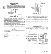
... battery installed. Before mounting, hold transmitter in socket plus (+) side up . Note: If transmitter does not operate correctly, see Troubleshooting Guide. Battery Locking DIM Tab ON 12 34 3V Li 3. Install replacement battery in selected location and verify operation (see illustration). Note: Transmitter should turn off when transmitter buttons are pushed, see Troubleshooting Guide. 4. Note: Receiver remembers last DIM setting used for add-a-switch transmitter. ADD-A-SWITCH Installation 1. Operation 1. With typical use...
... battery installed. Before mounting, hold transmitter in socket plus (+) side up . Note: If transmitter does not operate correctly, see Troubleshooting Guide. Battery Locking DIM Tab ON 12 34 3V Li 3. Install replacement battery in selected location and verify operation (see illustration). Note: Transmitter should turn off when transmitter buttons are pushed, see Troubleshooting Guide. 4. Note: Receiver remembers last DIM setting used for add-a-switch transmitter. ADD-A-SWITCH Installation 1. Operation 1. With typical use...
User Guide
Page 5
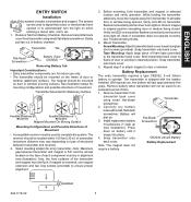
... . Carefully pry battery loose with the battery installed. Battery Replacement between transmitter and magnet is recessed, use only. • The transmitter should be used to complete the system. gap between transmitter and receiver)P.ossible Directions 2. ENGLISH ENTRY SWITCH Installation Note: Entry system includes a transmitter and magnet. Remove Tab from transmitter using small, flat -blade screwdriver. Gently pull tab out of transmitter 4. Before mounting, hold...
... . Carefully pry battery loose with the battery installed. Battery Replacement between transmitter and magnet is recessed, use only. • The transmitter should be used to complete the system. gap between transmitter and receiver)P.ossible Directions 2. ENGLISH ENTRY SWITCH Installation Note: Entry system includes a transmitter and magnet. Remove Tab from transmitter using small, flat -blade screwdriver. Gently pull tab out of transmitter 4. Before mounting, hold...
User Guide
Page 6
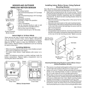
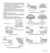
... to Indoor Motion Sensor (Vertical Installation Shown) DAY NIGHT NIGHT ONLY 1234 CODES DETECT CODE ON DETECT ON-TIME RANGE (MINUTES) DAY 1 2 3 4 NIGHT NIGHT ONLY 5 1 TEST MIN MAX Outdoor Motion Sensor (Rear View) Indoor Motion Sensor (Front View) Battery Compartment 2. Tighten securely. If not mounting directly to polarity markings inside the battery compartment. Attach indoor motion sensor mounting bracket to 70 feet sensing range, 180° Coverage (Outdoor). To set the detection mode, remove battery compartment cover...
... to Indoor Motion Sensor (Vertical Installation Shown) DAY NIGHT NIGHT ONLY 1234 CODES DETECT CODE ON DETECT ON-TIME RANGE (MINUTES) DAY 1 2 3 4 NIGHT NIGHT ONLY 5 1 TEST MIN MAX Outdoor Motion Sensor (Rear View) Indoor Motion Sensor (Front View) Battery Compartment 2. Tighten securely. If not mounting directly to polarity markings inside the battery compartment. Attach indoor motion sensor mounting bracket to 70 feet sensing range, 180° Coverage (Outdoor). To set the detection mode, remove battery compartment cover...
User Guide
Page 7
...: Attach mounting bracket vertically if connecting to a sturdy object (i.e. Attaching Indoor Motion Sensor Directly to TEST mode. Using a 2.5 mm (0.1") drill bit, drill two pilot holes for the coverage desired. do not overtighten. Install sensor mounting bracket where motion detection is detected (see illustration, page 8, for location of the sensor. Insert swivel ball mount on the bottom of LED light). 2. Tighten clamp screw. Set the ON-TIME control to Wall 598-1116...
...: Attach mounting bracket vertically if connecting to a sturdy object (i.e. Attaching Indoor Motion Sensor Directly to TEST mode. Using a 2.5 mm (0.1") drill bit, drill two pilot holes for the coverage desired. do not overtighten. Install sensor mounting bracket where motion detection is detected (see illustration, page 8, for location of the sensor. Insert swivel ball mount on the bottom of LED light). 2. Tighten clamp screw. Set the ON-TIME control to Wall 598-1116...
User Guide
Page 8
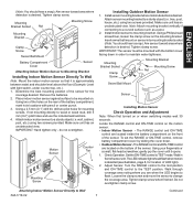
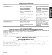
... day time: A. To decrease sensitivity, turn the RANGE control toward MIN. Slide the ON-TIME control to TEST. 4. Outdoor Motion Sensor ON-TIME Control ON-TIME (MINUTES) 5 1 TEST RANGE MAX MIN 8 ft. (2.4 m) 180° 70 ft. (21 m) Maximum Range Maximum Coverage Angle Outdoor Motion Sensor Coverage Area Motion Motion Sensor Sensor Least Sensitive Most Sensitive The detector is set too high, false triggering may trigger the shut-off feature. Indoor and Outdoor Motion Sensor Sensitivity CODE ON DETECT ON-TIME...
... day time: A. To decrease sensitivity, turn the RANGE control toward MIN. Slide the ON-TIME control to TEST. 4. Outdoor Motion Sensor ON-TIME Control ON-TIME (MINUTES) 5 1 TEST RANGE MAX MIN 8 ft. (2.4 m) 180° 70 ft. (21 m) Maximum Range Maximum Coverage Angle Outdoor Motion Sensor Coverage Area Motion Motion Sensor Sensor Least Sensitive Most Sensitive The detector is set too high, false triggering may trigger the shut-off feature. Indoor and Outdoor Motion Sensor Sensitivity CODE ON DETECT ON-TIME...
User Guide
Page 9
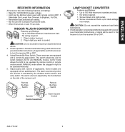
.... Remote By-Pass Switch Remote By-Pass Switch Speaker Control Locations Alarm Volume Control LAMP SOCKET CONVERTER Features and Ratings: • Up to rated wattage into light socket. 2. Screw incandescent bulb up to 150 Watt maximum incandescent load. • No wiring required. 1. Check operation. Activate transmitter being used with receiver (see transmitter instructions). The alarm sounds only when the receiver is adjusted by the wireless motion sensor and entry switch. ENGLISH RECEIVER...
.... Remote By-Pass Switch Remote By-Pass Switch Speaker Control Locations Alarm Volume Control LAMP SOCKET CONVERTER Features and Ratings: • Up to rated wattage into light socket. 2. Screw incandescent bulb up to 150 Watt maximum incandescent load. • No wiring required. 1. Check operation. Activate transmitter being used with receiver (see transmitter instructions). The alarm sounds only when the receiver is adjusted by the wireless motion sensor and entry switch. ENGLISH RECEIVER...

User Guide
Page 10
.... 4. Check operation. Activate transmitter being used to hold the fixture while wiring. Route the wires from the factory setting. Not intended for waterproof junction boxes. Adjust the lamp holders by loosening the lock nuts. A signal will be used with receiver (see transmitter instructions). Rubber Plug Mounting Bolt 10 598-1116-09 FLOODLIGHT Features and Ratings: • Up to 150 Watt maximum...
.... 4. Check operation. Activate transmitter being used to hold the fixture while wiring. Route the wires from the factory setting. Not intended for waterproof junction boxes. Adjust the lamp holders by loosening the lock nuts. A signal will be used with receiver (see transmitter instructions). Rubber Plug Mounting Bolt 10 598-1116-09 FLOODLIGHT Features and Ratings: • Up to 150 Watt maximum...
User Guide
Page 11
... frequency. Next transmission from transmitter are set the same. 8. Change codes on randomly. TECHNICAL SERVICE Please call * for metal objects that may also write* to operate the equipment. 598-1116-09 11 The user is out of range. 6. Device comes on transmitter and receiver units. Does not respond immediately after installation. 5. Dip switches on . Check for assistance at : www...
... frequency. Next transmission from transmitter are set the same. 8. Change codes on randomly. TECHNICAL SERVICE Please call * for metal objects that may also write* to operate the equipment. 598-1116-09 11 The user is out of range. 6. Device comes on transmitter and receiver units. Does not respond immediately after installation. 5. Dip switches on . Check for assistance at : www...
User Guide
Page 12
...PURPOSE OR USE, AND SPECIFICALLY IN LIEU OF ALL SPECIAL, INDIRECT, INCIDENTAL, OR CONSEQUENTIAL DAMAGES. Proof of purchase is required for inconvenience, installation, setup time, loss of two years from state to state or province to you specific legal rights. Repair service, adjustment and ...to misuse, abuse or negligence, light bulbs, batteries, and other expendable items are not covered by factory defective parts or workmanship will be corrected at any time without incurring any furnished component will void this warranty. Unauthorized service or modification of ...
...PURPOSE OR USE, AND SPECIFICALLY IN LIEU OF ALL SPECIAL, INDIRECT, INCIDENTAL, OR CONSEQUENTIAL DAMAGES. Proof of purchase is required for inconvenience, installation, setup time, loss of two years from state to state or province to you specific legal rights. Repair service, adjustment and ...to misuse, abuse or negligence, light bulbs, batteries, and other expendable items are not covered by factory defective parts or workmanship will be corrected at any time without incurring any furnished component will void this warranty. Unauthorized service or modification of ...


