Owner's Manual
Page 3
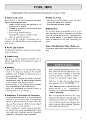
...may result in severe damage. Disassembly steps are in the opposite order of different adapters may cause damage to the tone bars and frame parts or topple the instrument, which is disconnected and the caster brakes are released. Assembly in the wrong order may be wiped off the ... the instrument or cause noise. • Make sure to adjust the wire clip positions after assembly. (YV-3910/3710/3700: P. 17) • Height adjustment of the striking surface (YV3910/3710/3700: P. 18, YV-2700/2700G/ 1600A/520: P 25) should be polished from high humidity to avoid corrosion and short circuit....
...may result in severe damage. Disassembly steps are in the opposite order of different adapters may cause damage to the tone bars and frame parts or topple the instrument, which is disconnected and the caster brakes are released. Assembly in the wrong order may be wiped off the ... the instrument or cause noise. • Make sure to adjust the wire clip positions after assembly. (YV-3910/3710/3700: P. 17) • Height adjustment of the striking surface (YV3910/3710/3700: P. 18, YV-2700/2700G/ 1600A/520: P 25) should be polished from high humidity to avoid corrosion and short circuit....
Owner's Manual
Page 5
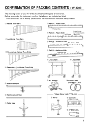
... The shipping carton of your YV-3700 should contain the parts shown below. q Natural Tone Bars i Rail (1) : Player Side w Accidental Tone Bars Name Plate o Rail (2) : Player Side Rail Clamp Posts (Larger number than parts !0 and !1) !0 Rail (3) : Audience Side Rail Clamp Posts e Resonators (Natural Tone Side) !1 Rail (4) : Audience Side YAMAHA Logo Posts !2 Leg (Large) !3 Leg...
... The shipping carton of your YV-3700 should contain the parts shown below. q Natural Tone Bars i Rail (1) : Player Side w Accidental Tone Bars Name Plate o Rail (2) : Player Side Rail Clamp Posts (Larger number than parts !0 and !1) !0 Rail (3) : Audience Side Rail Clamp Posts e Resonators (Natural Tone Side) !1 Rail (4) : Audience Side YAMAHA Logo Posts !2 Leg (Large) !3 Leg...
Owner's Manual
Page 6
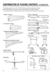
... The shipping carton of your YV-3910/3710 should contain the parts shown below. q Natural Tone Bars w Accidental Tone Bars u Rail (1) : Player Side Name Plate i Rail (2) : Player Side Rail Clamp Posts (Larger number than parts o and !0) o Rail (3) : Audience Side Rail Clamp Posts e Resonators (Natural Tone Side) !0 Rail (4) : Audience Side YAMAHA Logo Posts !1 Leg (Large...
... The shipping carton of your YV-3910/3710 should contain the parts shown below. q Natural Tone Bars w Accidental Tone Bars u Rail (1) : Player Side Name Plate i Rail (2) : Player Side Rail Clamp Posts (Larger number than parts o and !0) o Rail (3) : Audience Side Rail Clamp Posts e Resonators (Natural Tone Side) !0 Rail (4) : Audience Side YAMAHA Logo Posts !1 Leg (Large...
Owner's Manual
Page 7
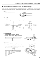
... and separate left and right sections and the pedal itself. q Pedal Stay The pedal stay divides into left and right sections. CONFIRMATION OF PACKING CONTENTS : YV-3910/3710 s Dividable Parts and Collapsible Parts (YV-3910/3710 only) The YV-3910's/YV-3710's large parts are properly aligned.
... and separate left and right sections and the pedal itself. q Pedal Stay The pedal stay divides into left and right sections. CONFIRMATION OF PACKING CONTENTS : YV-3910/3710 s Dividable Parts and Collapsible Parts (YV-3910/3710 only) The YV-3910's/YV-3710's large parts are properly aligned.
Owner's Manual
Page 8
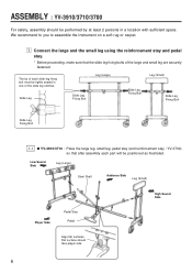
...(Small) Slide Leg Fixing Bolt Slide Leg Fixing Bolt Slide Leg Fixing Bolt 1-1 q YV-3910/3710 : Place the large leg, small leg, pedal stay (and reinforcement stay : YV-3700) so that the slide leg fixing bolts of each part will be positioned as illustrated. Low Sound Side Leg (Large) Slant Shaft Audience Side... performed by at least 2 persons in one of the slide leg notches. The tip of the large and small leg are securely fastened. ASSEMBLY : YV-3910/3710/3700 For safety, assembly should face player side. 6 We recommend to you to assemble the instrument on a soft rug or carpet.
...(Small) Slide Leg Fixing Bolt Slide Leg Fixing Bolt Slide Leg Fixing Bolt 1-1 q YV-3910/3710 : Place the large leg, small leg, pedal stay (and reinforcement stay : YV-3700) so that the slide leg fixing bolts of each part will be positioned as illustrated. Low Sound Side Leg (Large) Slant Shaft Audience Side... performed by at least 2 persons in one of the slide leg notches. The tip of the large and small leg are securely fastened. ASSEMBLY : YV-3910/3710/3700 For safety, assembly should face player side. 6 We recommend to you to assemble the instrument on a soft rug or carpet.
Owner's Manual
Page 10
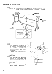
ASSEMBLY: YV-3910/3710/3700 1-1 q YV-3700 : Place the large leg, small leg, pedal stay (and reinforcement stay : YV3700) so that after assembly each part will go (aligning the notch with the small leg in the same way. Leg (Large) Fixing Bolt Leg (Large) Tighten Pedal Stay Notch ...Reference Hole Pedal Stay Notch 8 Flat surface should face player side. 1-2 q YV-3700 : Insert the pedal stay with its notch...
ASSEMBLY: YV-3910/3710/3700 1-1 q YV-3700 : Place the large leg, small leg, pedal stay (and reinforcement stay : YV3700) so that after assembly each part will go (aligning the notch with the small leg in the same way. Leg (Large) Fixing Bolt Leg (Large) Tighten Pedal Stay Notch ...Reference Hole Pedal Stay Notch 8 Flat surface should face player side. 1-2 q YV-3700 : Insert the pedal stay with its notch...
Owner's Manual
Page 14
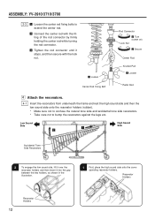
.... 1 First, place the high sound side onto the corre- z Loosen Center Rod Fixing Bolt Rod Connector x Turn (screw on) Lock Nut c Secure Center Rod Knurled Part z Loosen Pedal Rod v Attach the resonators. 4-1 Insert the resonators from underneath the frame and rest the high sound side and then the low sound side... to confuse the natural tone side and accidental tone side resonators. * Take care not to extend the center rod. Resonator Holders Resonator Holders 12 ASSEMBLY: YV-3910/3710/3700 3-3 z Loosen the center rod fixing bolts to bump the resonators against the legs etc.
.... 1 First, place the high sound side onto the corre- z Loosen Center Rod Fixing Bolt Rod Connector x Turn (screw on) Lock Nut c Secure Center Rod Knurled Part z Loosen Pedal Rod v Attach the resonators. 4-1 Insert the resonators from underneath the frame and rest the high sound side and then the low sound side... to confuse the natural tone side and accidental tone side resonators. * Take care not to extend the center rod. Resonator Holders Resonator Holders 12 ASSEMBLY: YV-3910/3710/3700 3-3 z Loosen the center rod fixing bolts to bump the resonators against the legs etc.
Owner's Manual
Page 15
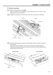
ASSEMBLY: YV-3910/3710/3700 b Set the tone bars. 5-1 (Refer to their posts, and then hook the two springs at the low sound side into each tone ... High Sound Side Springs 13 Align each other. Confirm that all strings are secured to the illustration of step 3-3 ) Raise the pedal until the knurled part is fully retracted, and fix the center rod by tightening the center rod fixing bolt. 5-2 Engage the rail clamp on rail (2) and rail (3) with rail...
ASSEMBLY: YV-3910/3710/3700 b Set the tone bars. 5-1 (Refer to their posts, and then hook the two springs at the low sound side into each tone ... High Sound Side Springs 13 Align each other. Confirm that all strings are secured to the illustration of step 3-3 ) Raise the pedal until the knurled part is fully retracted, and fix the center rod by tightening the center rod fixing bolt. 5-2 Engage the rail clamp on rail (2) and rail (3) with rail...
Owner's Manual
Page 17
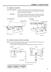
...*. Controller Screw Arrow Mark Driver 8P DIN Cable * In case the 8P DIN cable is misplaced, the following spare part may be ordered: Part No. ASSEMBLY: YV-3910/3710/3700 m Attach the controller. 7-1 q YV-3910/3710 : Loosen the fixing bolt, slide out the controller hanger and hang the controller on the high sound side...
...*. Controller Screw Arrow Mark Driver 8P DIN Cable * In case the 8P DIN cable is misplaced, the following spare part may be ordered: Part No. ASSEMBLY: YV-3910/3710/3700 m Attach the controller. 7-1 q YV-3910/3710 : Loosen the fixing bolt, slide out the controller hanger and hang the controller on the high sound side...
Owner's Manual
Page 18
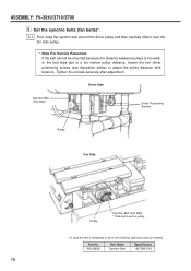
W5128092 Part Name Synchro Belt Specification 18OTN15-3.0 16 Tighten the screws securely after adjustment. Set the synchro belts (fan belts)*. 9-1 First, wrap the synchro belt around the ... fan side pulley. * Note For Service Personnel If the belt cannot be mounted because the distance between pulleys is misplaced or worn, the following spare part may be ordered: Part No. ASSEMBLY: YV-3910/3710/3700 .
W5128092 Part Name Synchro Belt Specification 18OTN15-3.0 16 Tighten the screws securely after adjustment. Set the synchro belts (fan belts)*. 9-1 First, wrap the synchro belt around the ... fan side pulley. * Note For Service Personnel If the belt cannot be mounted because the distance between pulleys is misplaced or worn, the following spare part may be ordered: Part No. ASSEMBLY: YV-3910/3710/3700 .
Owner's Manual
Page 20
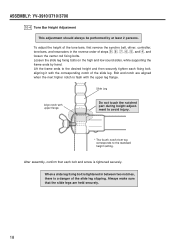
... and low sound sides, while supporting the frame ends by at least 2 persons. When a slide leg fixing bolt is tightened securely. ASSEMBLY: YV-3910/3710/3700 10-4 Tone Bar Height Adjustment This adjustment should always be performed by hand. Bolt and notch are held securely. 18 To adjust... the height of the slide leg slipping. Do not touch the notched part during height adjustment to avoid injury. * The fourth notch from top corresponds to the desired height and then securely tighten each bolt and ...
... and low sound sides, while supporting the frame ends by at least 2 persons. When a slide leg fixing bolt is tightened securely. ASSEMBLY: YV-3910/3710/3700 10-4 Tone Bar Height Adjustment This adjustment should always be performed by hand. Bolt and notch are held securely. 18 To adjust... the height of the slide leg slipping. Do not touch the notched part during height adjustment to avoid injury. * The fourth notch from top corresponds to the desired height and then securely tighten each bolt and ...
Owner's Manual
Page 22
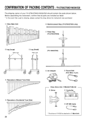
... Cable * The driver of your YV-2700/2700G/1600A/520 should contain the parts shown below. Before assembling the instrument, confirm that all parts are included as listed. * In the event that a part is attached to q Main Unit. CONFIRMATION OF PACKING CONTENTS : YV-2700/2700G/1600A/520 The shipping carton of YV-520 is missing, please contact the...
... Cable * The driver of your YV-2700/2700G/1600A/520 should contain the parts shown below. Before assembling the instrument, confirm that all parts are included as listed. * In the event that a part is attached to q Main Unit. CONFIRMATION OF PACKING CONTENTS : YV-2700/2700G/1600A/520 The shipping carton of YV-520 is missing, please contact the...
Owner's Manual
Page 24
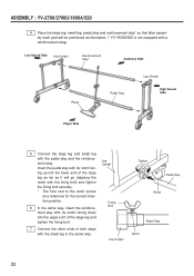
tion position. 6 In the same way, insert the reinforce- ASSEMBLY : YV-2700/2700G/1600A/520 4 Place the large leg, small leg, pedal stay and reinforcement stay* so that after assembly each part will go (aligning the notch with the small leg in the same way. Insert the pedal stay with the ...with the fixing bolt) and tighten the fixing bolt securely. * The hole next to the notch serves as it will be positioned as illustrated. (* YV-1600A/520 is not equipped with a reinforcement stay) Low Sound Side Leg (Large) Reinforcement Stay* Audience Side Pedal Pedal Stay Leg (Small) High ...
tion position. 6 In the same way, insert the reinforce- ASSEMBLY : YV-2700/2700G/1600A/520 4 Place the large leg, small leg, pedal stay and reinforcement stay* so that after assembly each part will go (aligning the notch with the small leg in the same way. Insert the pedal stay with the ...with the fixing bolt) and tighten the fixing bolt securely. * The hole next to the notch serves as it will be positioned as illustrated. (* YV-1600A/520 is not equipped with a reinforcement stay) Low Sound Side Leg (Large) Reinforcement Stay* Audience Side Pedal Pedal Stay Leg (Small) High ...
Owner's Manual
Page 25
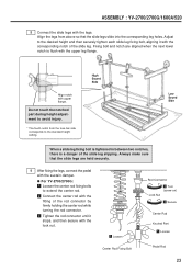
.... z Loosen Center Rod Fixing Bolt Rod Connector x Turn (screw on) Lock Nut c Secure Center Rod Knurled Part z Loosen Pedal Rod 23 Fixing bolt and notch are held securely. 9 After fixing the legs, connect the pedal... slide leg. Do not touch the notched part during height adjustment to the standard height setting. Always make sure that the slide legs slide into the corresponding leg holes. q For YV-2700/2700G: z Loosen the center rod fixing...flush with upper flange. Adjust to extend the center rod. ASSEMBLY : YV-2700/2700G/1600A/520 8 Connect the slide legs with the legs.
.... z Loosen Center Rod Fixing Bolt Rod Connector x Turn (screw on) Lock Nut c Secure Center Rod Knurled Part z Loosen Pedal Rod 23 Fixing bolt and notch are held securely. 9 After fixing the legs, connect the pedal... slide leg. Do not touch the notched part during height adjustment to the standard height setting. Always make sure that the slide legs slide into the corresponding leg holes. q For YV-2700/2700G: z Loosen the center rod fixing...flush with upper flange. Adjust to extend the center rod. ASSEMBLY : YV-2700/2700G/1600A/520 8 Connect the slide legs with the legs.
Owner's Manual
Page 26
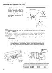
... mounted because the distance between the pulleys is misplaced or worn, the following spare part may be ordered: Model YV-2700/2700G YV-1600A/520 Part No. ASSEMBLY : YV-2700/2700G/1600A/520 q For YV-1600A/520 Loosen the center rod fixing bolts to YV-3910/3710/3700 assembly steps n through , on pages 14 and 15.) 12 Attach the...
... mounted because the distance between the pulleys is misplaced or worn, the following spare part may be ordered: Model YV-2700/2700G YV-1600A/520 Part No. ASSEMBLY : YV-2700/2700G/1600A/520 q For YV-1600A/520 Loosen the center rod fixing bolts to YV-3910/3710/3700 assembly steps n through , on pages 14 and 15.) 12 Attach the...
Owner's Manual
Page 27
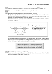
... center rod fixing bolts. (* To remove the tone bars, disengage the springs on page 19.) 25 Do not touch ! ASSEMBLY : YV-2700/2700G/1600A/520 13 Adjust the pedal stroke. (Refer to YV-3910/3710/3700 assembly step 10-1 on page 17.) 14 After assembly, confirm that the slide legs are aligned when... Supply", on the low sound side, and then unhook the string from the post.) Support both frame ends by hand (do not touch the metal parts shown in between two notches, there is tightened securely. 15 Height adjustment should always be performed by the wooden frame. Bolt and notch are held...
... center rod fixing bolts. (* To remove the tone bars, disengage the springs on page 19.) 25 Do not touch ! ASSEMBLY : YV-2700/2700G/1600A/520 13 Adjust the pedal stroke. (Refer to YV-3910/3710/3700 assembly step 10-1 on page 17.) 14 After assembly, confirm that the slide legs are aligned when... Supply", on the low sound side, and then unhook the string from the post.) Support both frame ends by hand (do not touch the metal parts shown in between two notches, there is tightened securely. 15 Height adjustment should always be performed by the wooden frame. Bolt and notch are held...

