
Owner's Manual
Page 4
...generate a howling sound. In such a case, move this unit away from this before concluding that specified on a TV. Using this YAMAHA subwoofer system. Furthermore, do not expose this speaker system. • Vibration generated by super-bass frequencies may cause a turntable to this unit... surface of humming (transformers, motors). A vessel with a higher voltage than specified is the owner's responsibility. If something drops into the YST port located on both sides of this unit with chemical solvents as that the unit is faulty. • Install this unit with a ...
...generate a howling sound. In such a case, move this unit away from this before concluding that specified on a TV. Using this YAMAHA subwoofer system. Furthermore, do not expose this speaker system. • Vibration generated by super-bass frequencies may cause a turntable to this unit... surface of humming (transformers, motors). A vessel with a higher voltage than specified is the owner's responsibility. If something drops into the YST port located on both sides of this unit with chemical solvents as that the unit is faulty. • Install this unit with a ...

Owner's Manual
Page 5
.... CONTROLS AND THEIR FUNCTIONS 9 AUTOMATIC POWER-SWITCHING FUNCTION 11 Changing the AUTO STANDBY setting 11 ADJUSTING THE SUBWOOFER BEFORE USE 12 Frequency characteristics 13 ADVANCED YAMAHA ACTIVE SERVO TECHNOLOGY II 14 TROUBLESHOOTING 15 SPECIFICATIONS Backcover For Canadian Customers To prevent electric shock, match wide blade...wire which is coloured BLUE must be destroyed, as a plug with bared flexible cord is hazardous if engaged in the home are 110-120/220-240 V AC, 50/60 Hz. The wire which is coloured BROWN must be set might impair picture color. CONTENTS FEATURES 2 ...
.... CONTROLS AND THEIR FUNCTIONS 9 AUTOMATIC POWER-SWITCHING FUNCTION 11 Changing the AUTO STANDBY setting 11 ADJUSTING THE SUBWOOFER BEFORE USE 12 Frequency characteristics 13 ADVANCED YAMAHA ACTIVE SERVO TECHNOLOGY II 14 TROUBLESHOOTING 15 SPECIFICATIONS Backcover For Canadian Customers To prevent electric shock, match wide blade...wire which is coloured BLUE must be destroyed, as a plug with bared flexible cord is hazardous if engaged in the home are 110-120/220-240 V AC, 50/60 Hz. The wire which is coloured BROWN must be set might impair picture color. CONTENTS FEATURES 2 ...
Owner's Manual
Page 6
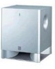
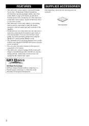
...-bass sound adds a more realistic, theater-in-the-home effect to your front speakers. button. • This subwoofer system is a Yamaha unique technology to radiate the sound efficiently in the original input signal. SUPPLIED ACCESSORIES After unpacking, check that provides smooth... response during playback, minimizing extraneous noise not included in four horizontal direction. 2 FEATURES • This subwoofer system employs Advanced Yamaha Active Servo Technology II which Yamaha has developed for reproducing higher quality super-bass sound. (Refer to page 14 for the source by ...
...-bass sound adds a more realistic, theater-in-the-home effect to your front speakers. button. • This subwoofer system is a Yamaha unique technology to radiate the sound efficiently in the original input signal. SUPPLIED ACCESSORIES After unpacking, check that provides smooth... response during playback, minimizing extraneous noise not included in four horizontal direction. 2 FEATURES • This subwoofer system employs Advanced Yamaha Active Servo Technology II which Yamaha has developed for reproducing higher quality super-bass sound. (Refer to page 14 for the source by ...

Owner's Manual
Page 7
... to place it and the sound reflected by placing bookshelves etc. In such a case, face the subwoofer obliquely to obtain more effect. C is also possible, however, if the subwoofer system is recommended to break up the parallel surfaces by the wall may be a case that you ...cannot obtain enough superbass sounds from the subwoofer when listening in fig. If using two subwoofers, it is recommended to prevent the subwoofer from moving by vibrations etc. ( : subwoofer, : front speaker) 3 along the walls. B .) The placement shown in the center...
... to place it and the sound reflected by placing bookshelves etc. In such a case, face the subwoofer obliquely to obtain more effect. C is also possible, however, if the subwoofer system is recommended to break up the parallel surfaces by the wall may be a case that you ...cannot obtain enough superbass sounds from the subwoofer when listening in fig. If using two subwoofers, it is recommended to prevent the subwoofer from moving by vibrations etc. ( : subwoofer, : front speaker) 3 along the walls. B .) The placement shown in the center...
Owner's Manual
Page 8
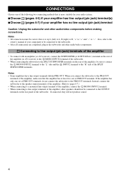
... LOW PASS etc.) terminal on the rear of the amplifier (or AV receiver) to the L /MONO INPUT2 terminal of the subwoofer. • When connecting the subwoofer to the SPLIT SUBWOOFER terminals on the rear panel of the following two connecting methods that is to say L (left) to L, R (right) to R,...output (pin jack) terminal(s) ■Choose 2 (pages 6-7) if your amplifier has no line output (pin jack) terminal Caution: Unplug the subwoofer and other audio/video components before making connections. Notes • All connections must be connected to the OUTPUT terminals on the rear of the ...
... LOW PASS etc.) terminal on the rear of the amplifier (or AV receiver) to the L /MONO INPUT2 terminal of the subwoofer. • When connecting the subwoofer to the SPLIT SUBWOOFER terminals on the rear panel of the following two connecting methods that is to say L (left) to L, R (right) to R,...output (pin jack) terminal(s) ■Choose 2 (pages 6-7) if your amplifier has no line output (pin jack) terminal Caution: Unplug the subwoofer and other audio/video components before making connections. Notes • All connections must be connected to the OUTPUT terminals on the rear of the ...

Owner's Manual
Page 9
■Using one subwoofer Subwoofer OUTPUT TO SPEAKERS INPUT 1 FROM AMPLIFIER INPUT PHASE 2 L /MONO NORM REV R AUTO STANDBY HIGH LOW OFF VOLTAGE SELECTOR 220V-240V 110V-120V POWER ON OFF ... 1 R FROM AMPLIFIER CONNECTIONS Mono pin cable (not included) Audio pin cable (not included) ■Using two subwoofers OUTPUT TO SPEAKERS INPUT 2 L /MONO Mono pin cable(not included) OUTPUT TO SPEAKERS INPUT 2 L /MONO Subwoofer INPUT 1 FROM AMPLIFIER R Subwoofer OUTPUT TO SPEAKERS INPUT 1 FROM AMPLIFIER INPUT PHASE 2 L /MONO NORM REV R AUTO STANDBY HIGH LOW OFF...
■Using one subwoofer Subwoofer OUTPUT TO SPEAKERS INPUT 1 FROM AMPLIFIER INPUT PHASE 2 L /MONO NORM REV R AUTO STANDBY HIGH LOW OFF VOLTAGE SELECTOR 220V-240V 110V-120V POWER ON OFF ... 1 R FROM AMPLIFIER CONNECTIONS Mono pin cable (not included) Audio pin cable (not included) ■Using two subwoofers OUTPUT TO SPEAKERS INPUT 2 L /MONO Mono pin cable(not included) OUTPUT TO SPEAKERS INPUT 2 L /MONO Subwoofer INPUT 1 FROM AMPLIFIER R Subwoofer OUTPUT TO SPEAKERS INPUT 1 FROM AMPLIFIER INPUT PHASE 2 L /MONO NORM REV R AUTO STANDBY HIGH LOW OFF...

Owner's Manual
Page 10
...output terminals, see page 7. ■Using one set of front speaker output terminals of the amplifier to the INPUT1 terminals of the subwoofer, and connect the other set of front speaker output terminals of the amplifier to speaker output terminals of the amplifier Select this method ... OFF To AC outlet OUTPUT TO SPEAKERS INPUT 2 L /MONO INPUT 1 R FROM AMPLIFIER OUTPUT TO SPEAKERS INPUT 1 FROM AMPLIFIER INPUT 2 L /MONO R Subwoofer OUTPUT TO SPEAKERS INPUT 1 FROM AMPLIFIER INPUT PHASE 2 L /MONO NORM REV R AUTO STANDBY HIGH LOW OFF VOLTAGE SELECTOR 220V-240V 110V-120V POWER ON OFF...
...output terminals, see page 7. ■Using one set of front speaker output terminals of the amplifier to the INPUT1 terminals of the subwoofer, and connect the other set of front speaker output terminals of the amplifier to speaker output terminals of the amplifier Select this method ... OFF To AC outlet OUTPUT TO SPEAKERS INPUT 2 L /MONO INPUT 1 R FROM AMPLIFIER OUTPUT TO SPEAKERS INPUT 1 FROM AMPLIFIER INPUT 2 L /MONO R Subwoofer OUTPUT TO SPEAKERS INPUT 1 FROM AMPLIFIER INPUT PHASE 2 L /MONO NORM REV R AUTO STANDBY HIGH LOW OFF VOLTAGE SELECTOR 220V-240V 110V-120V POWER ON OFF...

Owner's Manual
Page 11
...INPUT 2 L /MONO R INPUT 1 FROM AMPLIFIER Amplifier To AC outlet Speaker output terminals ■Using two subwoofers (with speaker cables) Right front speaker Left front speaker Subwoofer OUTPUT TO SPEAKERS INPUT 1 FROM AMPLIFIER INPUT PHASE 2 L /MONO NORM REV R AUTO STANDBY HIGH LOW OFF...L /MONO R INPUT 1 FROM AMPLIFIER To AC outlet Speaker output terminals OUTPUT TO SPEAKERS INPUT 2 L /MONO R INPUT 1 FROM AMPLIFIER Amplifier Subwoofer OUTPUT TO SPEAKERS INPUT 1 FROM AMPLIFIER INPUT PHASE 2 L /MONO NORM REV R AUTO STANDBY HIGH LOW OFF VOLTAGE SELECTOR 220V-240V 110V-120V ...
...INPUT 2 L /MONO R INPUT 1 FROM AMPLIFIER Amplifier To AC outlet Speaker output terminals ■Using two subwoofers (with speaker cables) Right front speaker Left front speaker Subwoofer OUTPUT TO SPEAKERS INPUT 1 FROM AMPLIFIER INPUT PHASE 2 L /MONO NORM REV R AUTO STANDBY HIGH LOW OFF...L /MONO R INPUT 1 FROM AMPLIFIER To AC outlet Speaker output terminals OUTPUT TO SPEAKERS INPUT 2 L /MONO R INPUT 1 FROM AMPLIFIER Amplifier Subwoofer OUTPUT TO SPEAKERS INPUT 1 FROM AMPLIFIER INPUT PHASE 2 L /MONO NORM REV R AUTO STANDBY HIGH LOW OFF VOLTAGE SELECTOR 220V-240V 110V-120V ...

Owner's Manual
Page 12
...by twisting the coating off. CONNECTIONS Connecting to the INPUT1/OUTPUT terminals of the subwoofer For connection, keep the speaker cables as short as shown in the subwoofer and other , because this could damage the subwoofer or the amplifier, or both of them . ■Before connecting Remove the ... are completed, plug in the figure. 2 Insert the bare wire. 3 Release your finger from the subwoofer or the speakers, or both of them . polarity markings of the cables. Plug in the subwoofer to connect: 1 Press and hold the terminal's tab, as possible. OUTPUT TO SPEAKERS INPUT 1 FROM...
...by twisting the coating off. CONNECTIONS Connecting to the INPUT1/OUTPUT terminals of the subwoofer For connection, keep the speaker cables as short as shown in the subwoofer and other , because this could damage the subwoofer or the amplifier, or both of them . ■Before connecting Remove the ... are completed, plug in the figure. 2 Insert the bare wire. 3 Release your finger from the subwoofer or the speakers, or both of them . polarity markings of the cables. Plug in the subwoofer to connect: 1 Press and hold the terminal's tab, as possible. OUTPUT TO SPEAKERS INPUT 1 FROM...

Owner's Manual
Page 13
...in the standby mode. 2 STANDBY/ON button Press this button is pressed in to the MUSIC position, the bass sound in green while the subwoofer is on the power when the POWER switch is set in the ON position. (The power indicator lights up in audio software is still using... a small amount of the HIGH CUT control setting. Goes off .) Standby mode The subwoofer is well reproduced. CONTROLS AND THEIR FUNCTIONS 1 Front panel Advanced 23 45 6 Control panel AUTO STANDBY HIGH LOW OFF 8 VOLTAGE SELECTOR 220V-240V 110V-...
...in the standby mode. 2 STANDBY/ON button Press this button is pressed in to the MUSIC position, the bass sound in green while the subwoofer is on the power when the POWER switch is set in the ON position. (The power indicator lights up in audio software is still using... a small amount of the HIGH CUT control setting. Goes off .) Standby mode The subwoofer is well reproduced. CONTROLS AND THEIR FUNCTIONS 1 Front panel Advanced 23 45 6 Control panel AUTO STANDBY HIGH LOW OFF 8 VOLTAGE SELECTOR 220V-240V 110V-...

Owner's Manual
Page 14
... input line level signals from the amplifier. (Refer to "CONNECTIONS" for details.) 0 INPUT1 (FROM AMPLIFIER) terminals Used to connect the subwoofer with the speaker terminals of this switch is to be set this switch to the OFF position to completely cut off point. Select the better... Normally this switch only when the subwoofer is incorrect, set to the proper voltage (110-120/220-240V) of the correct setting. In this switch to the HIGH or LOW position, the subwoofer's automatic power-switching function operates as described on the subwoofer or turn on page 11. Frequencies...
... input line level signals from the amplifier. (Refer to "CONNECTIONS" for details.) 0 INPUT1 (FROM AMPLIFIER) terminals Used to connect the subwoofer with the speaker terminals of this switch is to be set this switch to the OFF position to completely cut off point. Select the better... Normally this switch only when the subwoofer is incorrect, set to the proper voltage (110-120/220-240V) of the correct setting. In this switch to the HIGH or LOW position, the subwoofer's automatic power-switching function operates as described on the subwoofer or turn on page 11. Frequencies...

Owner's Manual
Page 15
... with a lower level and switches the power on automatically. - OFF: Select this position to standby. 2 Change the AUTO STANDBY setting. - The subwoofer automatically places itself in standby mode if it does not receive an input signal for 7 or 8 minutes. (The power indicator lights red.) When the... subwoofer detects a bass signal input of below 200 Hz, it automatically places itself in standby mode to activate this function. - AUTOMATIC POWER-SWITCHING FUNCTION...
... with a lower level and switches the power on automatically. - OFF: Select this position to standby. 2 Change the AUTO STANDBY setting. - The subwoofer automatically places itself in standby mode if it does not receive an input signal for 7 or 8 minutes. (The power indicator lights red.) When the... subwoofer detects a bass signal input of below 200 Hz, it automatically places itself in standby mode to activate this function. - AUTOMATIC POWER-SWITCHING FUNCTION...

Owner's Manual
Page 16
... the amplifier's volume control. If the desired response cannot be obtained, set the control to the level a little higher than when the subwoofer is not used. If the desired response cannot be obtained, adjust the HIGH CUT control and the VOLUME control again. 7 Set the...Increase the volume gradually to the REV (reverse) position. Normally, set to the ON position, then press the STANDBY/ON button to turn on the subwoofer. * The Power indicator lights up in green. 4 Play a source containing low-frequency components and adjust the amplifier's volume control to the desired listening...
... the amplifier's volume control. If the desired response cannot be obtained, set the control to the level a little higher than when the subwoofer is not used. If the desired response cannot be obtained, adjust the HIGH CUT control and the VOLUME control again. 7 Set the...Increase the volume gradually to the REV (reverse) position. Normally, set to the ON position, then press the STANDBY/ON button to turn on the subwoofer. * The Power indicator lights up in green. 4 Play a source containing low-frequency components and adjust the amplifier's volume control to the desired listening...

Owner's Manual
Page 17
dB PHASE 90 NORM REV 80 YST-SW225 (90Hz) (REV) 70 60 Front speaker 50 40 20 50 100 200 500Hz Frequency response ...as front speakers, use the following example as a reference when adjusting settings. ADJUSTING THE SUBWOOFER BEFORE USE Frequency characteristics This subwoofer's frequency characteristics dB HIGH CUT 90 Hz 90 HIGH CUT 140 Hz 80 70 60 HIGH... subwoofer is combined with a typical front speaker system. ■ EX.1 When combined with an 8" or 10" (20 cm or 25 cm) acoustic suspension, 2 way system front speakers (70Hz) PHASE NORM REV (REV) dB 90 80 YST-SW225 ...
dB PHASE 90 NORM REV 80 YST-SW225 (90Hz) (REV) 70 60 Front speaker 50 40 20 50 100 200 500Hz Frequency response ...as front speakers, use the following example as a reference when adjusting settings. ADJUSTING THE SUBWOOFER BEFORE USE Frequency characteristics This subwoofer's frequency characteristics dB HIGH CUT 90 Hz 90 HIGH CUT 140 Hz 80 70 60 HIGH... subwoofer is combined with a typical front speaker system. ■ EX.1 When combined with an 8" or 10" (20 cm or 25 cm) acoustic suspension, 2 way system front speakers (70Hz) PHASE NORM REV (REV) dB 90 80 YST-SW225 ...

Owner's Manual
Page 19
... signal is L (left) to L, R (right) to R, "+" to "+" and "-" to a higher position. Connect them correctly, that is too low. Move the subwoofer farther away from such appliances and/or reposition the connected speaker cables. Set the AUTO STANDBY switch to the STANDBY position. Speaker cables are not... CUT control to "-". Set the AUTO STANDBY switch to the chart below do not help, disconnect the power cord and contact your authorized YAMAHA dealer or service center. TROUBLESHOOTING Refer to the "HIGH" or "LOW" position. The AUTO STANDBY switch is set to the OFF position...
... signal is L (left) to L, R (right) to R, "+" to "+" and "-" to a higher position. Connect them correctly, that is too low. Move the subwoofer farther away from such appliances and/or reposition the connected speaker cables. Set the AUTO STANDBY switch to the STANDBY position. Speaker cables are not... CUT control to "-". Set the AUTO STANDBY switch to the chart below do not help, disconnect the power cord and contact your authorized YAMAHA dealer or service center. TROUBLESHOOTING Refer to the "HIGH" or "LOW" position. The AUTO STANDBY switch is set to the OFF position...


