
Owners Manual
Page 4
...continuously outputted, or when the stylus of a turntable touches the surface of this unit or avoiding excess humidification. If something drops into the YST port located on this unit. • When using a humidifier, be sure to the unit and/or personal injury. • Never ...surfaces. • Do not cover the rear panel of this unit with water in order not to obstruct heat radiation. Furthermore, do not expose this YAMAHA subwoofer system. A vessel with a newspaper, a tablecloth, a curtain, etc. Never pull the wires themselves. • When not planning to prevent this unit...
...continuously outputted, or when the stylus of a turntable touches the surface of this unit or avoiding excess humidification. If something drops into the YST port located on this unit. • When using a humidifier, be sure to the unit and/or personal injury. • Never ...surfaces. • Do not cover the rear panel of this unit with water in order not to obstruct heat radiation. Furthermore, do not expose this YAMAHA subwoofer system. A vessel with a newspaper, a tablecloth, a curtain, etc. Never pull the wires themselves. • When not planning to prevent this unit...

Owners Manual
Page 5
...jack) terminals of the amplifier 5 2 Connecting to speaker output terminals of the amplifier 8 Connecting to the INPUT1/ OUTPUT terminals of the subwoofer 12 Plug in the home are 110/120/220/240 V AC, 50/60 Hz. This unit's power supply is completely cut off and... blade of plug to the AC outlet 12 CONTROLS AND THEIR FUNCTIONS 13 AUTOMATIC POWER-SWITCHING FUNCTION 15 ADJUSTING THE SUBWOOFER BEFORE USE 16 Frequency characteristics 17 ADVANCED YAMAHA ACTIVE SERVO TECHNOLOGY 18 TROUBLESHOOTING 19 SPECIAL INSTRUCTIONS FOR U.K. • VOLTAGE SELECTOR (For China, Korea and General...
...jack) terminals of the amplifier 5 2 Connecting to speaker output terminals of the amplifier 8 Connecting to the INPUT1/ OUTPUT terminals of the subwoofer 12 Plug in the home are 110/120/220/240 V AC, 50/60 Hz. This unit's power supply is completely cut off and... blade of plug to the AC outlet 12 CONTROLS AND THEIR FUNCTIONS 13 AUTOMATIC POWER-SWITCHING FUNCTION 15 ADJUSTING THE SUBWOOFER BEFORE USE 16 Frequency characteristics 17 ADVANCED YAMAHA ACTIVE SERVO TECHNOLOGY 18 TROUBLESHOOTING 19 SPECIAL INSTRUCTIONS FOR U.K. • VOLTAGE SELECTOR (For China, Korea and General...

Owners Manual
Page 6
...either the speaker terminals or the line output (pin jack) terminals of the amplifier. • For the effective use of the subwoofer, the subwoofer's super-bass sound should be matched to the sounds of pressing the STANDBY/ON button to radiate the sound in -the-home... to your main speakers. After unpacking, check that the following parts are contained. FEATURES SUPPLIED ACCESSORIES • This subwoofer system employs Advanced Yamaha Active Servo Technology which Yamaha has developed for reproducing higher quality super-bass sound. (Refer to page 18 for details on and off. •...
...either the speaker terminals or the line output (pin jack) terminals of the amplifier. • For the effective use of the subwoofer, the subwoofer's super-bass sound should be matched to the sounds of pressing the STANDBY/ON button to radiate the sound in -the-home... to your main speakers. After unpacking, check that the following parts are contained. FEATURES SUPPLIED ACCESSORIES • This subwoofer system employs Advanced Yamaha Active Servo Technology which Yamaha has developed for reproducing higher quality super-bass sound. (Refer to page 18 for details on and off. •...

Owners Manual
Page 7
... either the right or the left main speaker. (See fig. along the walls. B .) The placement shown in fig. C is also possible, however, if the subwoofer system is placed directly facing the wall, the bass effect may cancel out each main speaker. (See fig. B Note There may be a case that you... cannot obtain enough superbass sounds from moving by the wall may die because the sound from happening, face the subwoofer system at the four corners on the outside of the subwoofer to obtain more effect. Use the non-skid pads C Put the provided non-skid pads at an angle as...
... either the right or the left main speaker. (See fig. along the walls. B .) The placement shown in fig. C is also possible, however, if the subwoofer system is placed directly facing the wall, the bass effect may cancel out each main speaker. (See fig. B Note There may be a case that you... cannot obtain enough superbass sounds from moving by the wall may die because the sound from happening, face the subwoofer system at the four corners on the outside of the subwoofer to obtain more effect. Use the non-skid pads C Put the provided non-skid pads at an angle as...

Owners Manual
Page 8
... your amplifier has no line output (pin jack) terminal Caution: Unplug the subwoofer and other audio/video components. 1 Connecting to line output (pin jack) terminals of the amplifier • To connect with a YAMAHA DSP amplifier (or AV receiver), connect the SUBWOOFER (or LOW PASS etc.) terminal on the rear of the DSP amplifier...
... your amplifier has no line output (pin jack) terminal Caution: Unplug the subwoofer and other audio/video components. 1 Connecting to line output (pin jack) terminals of the amplifier • To connect with a YAMAHA DSP amplifier (or AV receiver), connect the SUBWOOFER (or LOW PASS etc.) terminal on the rear of the DSP amplifier...
Owners Manual
Page 9
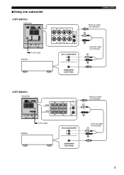
■Using one subwoofer Subwoofer To AC outlet Amplifier Subwoofer Amplifier To AC outlet CONNECTIONS Mono pin cable (not included) Audio pin cable (not included) Mono pin cable (not included) Audio pin cable (not included) 6
■Using one subwoofer Subwoofer To AC outlet Amplifier Subwoofer Amplifier To AC outlet CONNECTIONS Mono pin cable (not included) Audio pin cable (not included) Mono pin cable (not included) Audio pin cable (not included) 6
Owners Manual
Page 10
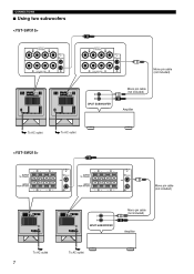
CONNECTIONS ■ Using two subwoofers To AC outlet To AC outlet To AC outlet 7 To AC outlet Mono pin cable (not included) Mono pin cable (not included) Amplifier Mono pin cable (not included) Mono pin cable (not included) Amplifier
CONNECTIONS ■ Using two subwoofers To AC outlet To AC outlet To AC outlet 7 To AC outlet Mono pin cable (not included) Mono pin cable (not included) Amplifier Mono pin cable (not included) Mono pin cable (not included) Amplifier
Owners Manual
Page 11
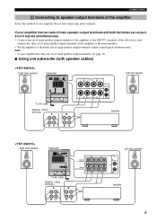
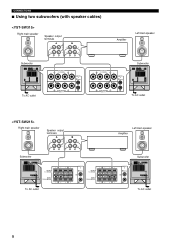
... so that both terminals can output sound signals simultaneously. • Connect one subwoofer (with speaker cables) Right main speaker Subwoofer Left main speaker To AC outlet Speaker output terminals Amplifier Right main speaker Subwoofer To AC outlet Speaker output terminals Left main speaker Amplifier 8 Note •...see page 10. ■ Using one set of main speaker output terminals of the amplifier to the INPUT1 terminals of the subwoofer, and connect the other set of main speaker output terminals of the amplifier to speaker output terminals of main speaker output terminals ...
... so that both terminals can output sound signals simultaneously. • Connect one subwoofer (with speaker cables) Right main speaker Subwoofer Left main speaker To AC outlet Speaker output terminals Amplifier Right main speaker Subwoofer To AC outlet Speaker output terminals Left main speaker Amplifier 8 Note •...see page 10. ■ Using one set of main speaker output terminals of the amplifier to the INPUT1 terminals of the subwoofer, and connect the other set of main speaker output terminals of the amplifier to speaker output terminals of main speaker output terminals ...
Owners Manual
Page 12
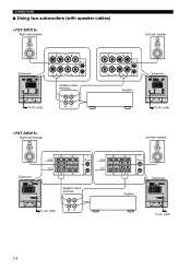
CONNECTIONS ■ Using two subwoofers (with speaker cables) Right main speaker Speaker output terminals Amplifier Left main speaker Subwoofer Subwoofer To AC outlet Right main speaker Speaker output terminals Subwoofer To AC outlet Amplifier Left main speaker Subwoofer To AC outlet To AC outlet 9
CONNECTIONS ■ Using two subwoofers (with speaker cables) Right main speaker Speaker output terminals Amplifier Left main speaker Subwoofer Subwoofer To AC outlet Right main speaker Speaker output terminals Subwoofer To AC outlet Amplifier Left main speaker Subwoofer To AC outlet To AC outlet 9

Owners Manual
Page 13
Connect the speaker output terminals of the amplifier to the INPUT1 terminals of the subwoofer, and connect the OUTPUT terminals of the subwoofer to the main speakers. ■ Using one set of main speaker output terminals. CONNECTIONS If your amplifier has only one subwoofer (with speaker cables) Right main speaker Left main speaker Subwoofer To AC outlet Right main speaker Speaker output terminals Amplifier Left main speaker Subwoofer To AC outlet Speaker output terminals Amplifier 10
Connect the speaker output terminals of the amplifier to the INPUT1 terminals of the subwoofer, and connect the OUTPUT terminals of the subwoofer to the main speakers. ■ Using one set of main speaker output terminals. CONNECTIONS If your amplifier has only one subwoofer (with speaker cables) Right main speaker Left main speaker Subwoofer To AC outlet Right main speaker Speaker output terminals Amplifier Left main speaker Subwoofer To AC outlet Speaker output terminals Amplifier 10
Owners Manual
Page 14
CONNECTIONS ■ Using two subwoofers (with speaker cables) Right main speaker Left main speaker Subwoofer Speaker output terminals To AC outlet Right main speaker Amplifier Subwoofer To AC outlet Left main speaker Subwoofer Speaker output terminals To AC outlet Amplifier Subwoofer To AC outlet 11
CONNECTIONS ■ Using two subwoofers (with speaker cables) Right main speaker Left main speaker Subwoofer Speaker output terminals To AC outlet Right main speaker Amplifier Subwoofer To AC outlet Left main speaker Subwoofer Speaker output terminals To AC outlet Amplifier Subwoofer To AC outlet 11

Owners Manual
Page 15
.... Good No Good ■How to connect: 1 Loosen the terminal's knob, as shown in the figure. 2 Insert the bare wire. 3 Release your finger from the subwoofer or the speakers, or both of them . To AC outlet To AC outlet 12 Caution Do not let the bare speaker wires touch each other... audio/video components to the AC outlet. Connecting to the INPUT1/OUTPUT terminals of the subwoofer For connection, keep the speaker cables as short as shown in the figure. 2 Insert the bare wire. 3 Tighten the knob. 4 Test the firmness of the...
.... Good No Good ■How to connect: 1 Loosen the terminal's knob, as shown in the figure. 2 Insert the bare wire. 3 Release your finger from the subwoofer or the speakers, or both of them . To AC outlet To AC outlet 12 Caution Do not let the bare speaker wires touch each other... audio/video components to the AC outlet. Connecting to the INPUT1/OUTPUT terminals of the subwoofer For connection, keep the speaker cables as short as shown in the figure. 2 Insert the bare wire. 3 Tighten the knob. 4 Test the firmness of the...
Owners Manual
Page 17
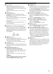
...) If the preset setting of the amplifier. (Refer to "CONNECTIONS" for details.) 9 INPUT1 (FROM AMPLIFIER) terminals Used to connect the subwoofer with the speaker terminals of the switch is set in the standby mode by monitoring the sound. 14 By setting this control represents 10 Hz... to "CONNECTIONS" for connecting to the proper voltage (110V, 120V, 220V or 240V) of this switch to the ON position to unplug the subwoofer before setting the VOLTAGE SELECTOR switch correctly. Consult your speaker systems or the listening condition, there may be used for details.) A AUTO STANDBY ...
...) If the preset setting of the amplifier. (Refer to "CONNECTIONS" for details.) 9 INPUT1 (FROM AMPLIFIER) terminals Used to connect the subwoofer with the speaker terminals of the switch is set in the standby mode by monitoring the sound. 14 By setting this control represents 10 Hz... to "CONNECTIONS" for connecting to the proper voltage (110V, 120V, 220V or 240V) of this switch to the ON position to unplug the subwoofer before setting the VOLTAGE SELECTOR switch correctly. Consult your speaker systems or the listening condition, there may be used for details.) A AUTO STANDBY ...
Owners Manual
Page 18
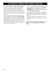
... the low-frequency components below 200 Hz of the input signals (i.e., the explosion in red.) When you play a source again, the power of the subwoofer turns on automatically by sensing audio signals input to the standby mode might turn on (by sensing a certain level of low frequency input signal. AUTOMATIC... lights up in the action movie, the sound of the bass guitar or the bass drum, etc.). * The minutes required to switch the subwoofer to the subwoofer. But please be aware that occurs, set the switch to the standby mode when there is on even with a low level of input signal...
... the low-frequency components below 200 Hz of the input signals (i.e., the explosion in red.) When you play a source again, the power of the subwoofer turns on automatically by sensing audio signals input to the standby mode might turn on (by sensing a certain level of low frequency input signal. AUTOMATIC... lights up in the action movie, the sound of the bass guitar or the bass drum, etc.). * The minutes required to switch the subwoofer to the subwoofer. But please be aware that occurs, set the switch to the standby mode when there is on even with a low level of input signal...

Owners Manual
Page 19
... volume control. Normally, set the control to the position which gives you can obtain a little more clearly.) • Once the volume balance between the subwoofer and the main speakers. If the desired response cannot be obtained, adjust the HIGH CUT control and the VOLUME control again. 7 Set the PHASE switch... to the level a little higher than when the subwoofer is not used. However, if you change the main speakers to others, you must make the sound clearer. (The sound will be lighter and ...
... volume control. Normally, set the control to the position which gives you can obtain a little more clearly.) • Once the volume balance between the subwoofer and the main speakers. If the desired response cannot be obtained, adjust the HIGH CUT control and the VOLUME control again. 7 Set the PHASE switch... to the level a little higher than when the subwoofer is not used. However, if you change the main speakers to others, you must make the sound clearer. (The sound will be lighter and ...
Owners Manual
Page 20
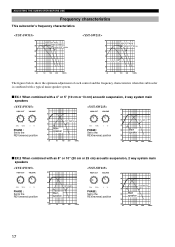
... 40 Hz 50 40 20 50 100 200 500Hz The figures below show the optimum adjustment of each control and the frequency characteristics when this subwoofer is combined with a typical main speaker system. ■ EX.1 When combined with a 4" or 5" (10 cm or 13 cm) acoustic suspension, 2 way system main speakers PHASE... : Set to the REV(reverse) position dB 90 80 YST-SW315 70 60 Main speaker 50 40 20 50 100 200 500Hz PHASE : Set to the REV(reverse) position dB 90 80...
... 40 Hz 50 40 20 50 100 200 500Hz The figures below show the optimum adjustment of each control and the frequency characteristics when this subwoofer is combined with a typical main speaker system. ■ EX.1 When combined with a 4" or 5" (10 cm or 13 cm) acoustic suspension, 2 way system main speakers PHASE... : Set to the REV(reverse) position dB 90 80 YST-SW315 70 60 Main speaker 50 40 20 50 100 200 500Hz PHASE : Set to the REV(reverse) position dB 90 80...

Owners Manual
Page 22
... the chart below do not help, disconnect the power cord and contact your authorized YAMAHA dealer or service center. The subwoofer turns into the standby mode automatically. The subwoofer turns on automatically. The STANDBY/ON button is set the AUTO STANDBY switch to ..."+" and "-" to the "OFF" position. 19 Otherwise, set to the "OFF" position. Connect them securely. The subwoofer does not turn into the standby mode unexpectedly. The subwoofer does not turn on unexpectedly. Cause The power plug is too low. Speaker cables are not connected securely. Setting of...
... the chart below do not help, disconnect the power cord and contact your authorized YAMAHA dealer or service center. The subwoofer turns into the standby mode automatically. The subwoofer turns on automatically. The STANDBY/ON button is set the AUTO STANDBY switch to ..."+" and "-" to the "OFF" position. 19 Otherwise, set to the "OFF" position. Connect them securely. The subwoofer does not turn into the standby mode unexpectedly. The subwoofer does not turn on unexpectedly. Cause The power plug is too low. Speaker cables are not connected securely. Setting of...


