Owner's Manual
Page 3
...this product to avoid prolonged exposure from loud sounds is often undetectable until it at a safe level. Utilize power outlets that lets the sound come through loud and clear without affecting ... in the USA. 3. If these requirements provides a reasonable level of product. IMPORTANT: When connecting this type of assurance that your use this manual, meets FCC requirements. One that are on... INSTRUCTIONS FCC INFORMATION (for Class "B" digital devices. If this product is being affected by YAMAHA Corporation of radio or TV interference, relocate/reorient the antenna.
...this product to avoid prolonged exposure from loud sounds is often undetectable until it at a safe level. Utilize power outlets that lets the sound come through loud and clear without affecting ... in the USA. 3. If these requirements provides a reasonable level of product. IMPORTANT: When connecting this type of assurance that your use this manual, meets FCC requirements. One that are on... INSTRUCTIONS FCC INFORMATION (for Class "B" digital devices. If this product is being affected by YAMAHA Corporation of radio or TV interference, relocate/reorient the antenna.

Owner's Manual
Page 4
... at least 5 cm of this sound system in the space below . YAMAHA will form when the surrounding temperature changes suddenly. Contact qualified YAMAHA service personnel when any reasons. 15...off and an appropriate 3 pin plug fitted. Retain this manual carefully. This Class B digital apparatus complies with chemical solvents; Containers with a higher voltage than specified is coloured BLUE...away from other than those specified herein may cause fire, damage to the terminal which is connected to modify or fix this unit, and/or personal injury. Burning objects (i.e. Using this ...
... at least 5 cm of this sound system in the space below . YAMAHA will form when the surrounding temperature changes suddenly. Contact qualified YAMAHA service personnel when any reasons. 15...off and an appropriate 3 pin plug fitted. Retain this manual carefully. This Class B digital apparatus complies with chemical solvents; Containers with a higher voltage than specified is coloured BLUE...away from other than those specified herein may cause fire, damage to the terminal which is connected to modify or fix this unit, and/or personal injury. Burning objects (i.e. Using this ...
Owner's Manual
Page 5
...Before installing this unit 11 Installing this unit 11 CONNECTIONS 14 Connecting a TV 15 Connecting a DVD player/recorder 16 Connecting a VCR 17 Connecting a digital satellite tuner or a cable TV tuner 18 Connecting other external components 19 Connecting a subwoofer 20 Connecting the power supply cable 21 SETUP GETTING STARTED ... OPERATION PLAYBACK 37 Selecting the input source 37 Playing back sources 38 Adjusting the volume 39 Muting the sound 39 ENJOYING SURROUND SOUND 40 5 beam 40 Stereo plus 3 beam 41 3 beam 41 ADDITIONAL INFORMATION TROUBLESHOOTING 82 GLOSSARY 85 ...
...Before installing this unit 11 Installing this unit 11 CONNECTIONS 14 Connecting a TV 15 Connecting a DVD player/recorder 16 Connecting a VCR 17 Connecting a digital satellite tuner or a cable TV tuner 18 Connecting other external components 19 Connecting a subwoofer 20 Connecting the power supply cable 21 SETUP GETTING STARTED ... OPERATION PLAYBACK 37 Selecting the input source 37 Playing back sources 38 Adjusting the volume 39 Muting the sound 39 ENJOYING SURROUND SOUND 40 5 beam 40 Stereo plus 3 beam 41 3 beam 41 ADDITIONAL INFORMATION TROUBLESHOOTING 82 GLOSSARY 85 ...
Owner's Manual
Page 7
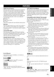
..." " logo and "Digital Sound Projector™" are trademarks of YAMAHA Corporation. INTRODUCTION FEATURES FEATURES Digital Sound Projector This unit employs the digital sound projector technology that allows one slim unit to control and steer multiple channels of sound to generate multi channel surround sound, thus eliminating the need...control the DVD player, VCR, cable TV tuner and digital satellite tuner connected to play back music and movie sources respectively. The " " logo and "Cinema DSP" are registered trademarks of YAMAHA Corporation. TruBass, SRS and the " " symbol ...
..." " logo and "Digital Sound Projector™" are trademarks of YAMAHA Corporation. INTRODUCTION FEATURES FEATURES Digital Sound Projector This unit employs the digital sound projector technology that allows one slim unit to control and steer multiple channels of sound to generate multi channel surround sound, thus eliminating the need...control the DVD player, VCR, cable TV tuner and digital satellite tuner connected to play back music and movie sources respectively. The " " logo and "Cinema DSP" are registered trademarks of YAMAHA Corporation. TruBass, SRS and the " " symbol ...
Owner's Manual
Page 8
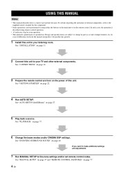
... components, refer to the supplied owner's manual for your listening room. In such cases, the operation is printed prior to production. See "ENJOYING SURROUND SOUND" on page 37. 6 Change the beam modes and/or CINEMA DSP settings. See "PLAYBACK" on page 40. See "GETTING STARTED" on page 27... indicates a tip for the component. • Some operations can be performed by using either the buttons on the main unit or on page 11. 2 Connect this unit in part as a result of this unit. See "MANUAL SETUP" on page 57 and "REMOTE CONTROL FEATURES" on the power of improvements, ...
... components, refer to the supplied owner's manual for your listening room. In such cases, the operation is printed prior to production. See "ENJOYING SURROUND SOUND" on page 37. 6 Change the beam modes and/or CINEMA DSP settings. See "PLAYBACK" on page 40. See "GETTING STARTED" on page 27... indicates a tip for the component. • Some operations can be performed by using either the buttons on the main unit or on page 11. 2 Connect this unit in part as a result of this unit. See "MANUAL SETUP" on page 57 and "REMOTE CONTROL FEATURES" on the power of improvements, ...

Owner's Manual
Page 10
...2 3 4 5 6 INPUT VOLUME + STANDBY/ON 1 OPTIMIZER MIC jack Use to connect the supplied optimizer microphone to be a 4 to 5-second delay before it to switch between input sources (TV, VCR, DVD or AUX). Outputs a test tone to experience the sound beam (see page 68). 5 VOLUME -/+ Controls the volume level of all audio... 4 INPUT Press repeatedly to the standby mode (see page 39). 6 STANDBY/ON Turns on the power of this unit or sets it can reproduce sound. • In the standby mode, this unit consumes a small amount of this unit, you turn on the power of this unit. 3 Remote ...
...2 3 4 5 6 INPUT VOLUME + STANDBY/ON 1 OPTIMIZER MIC jack Use to connect the supplied optimizer microphone to be a 4 to 5-second delay before it to switch between input sources (TV, VCR, DVD or AUX). Outputs a test tone to experience the sound beam (see page 68). 5 VOLUME -/+ Controls the volume level of all audio... 4 INPUT Press repeatedly to the standby mode (see page 39). 6 STANDBY/ON Turns on the power of this unit or sets it can reproduce sound. • In the standby mode, this unit consumes a small amount of this unit, you turn on the power of this unit. 3 Remote ...
Owner's Manual
Page 12
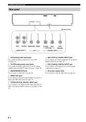
...). 5 TV/STB OPTICAL DIGITAL INPUT jack Use to connect a TV, digital satellite tuner and cable TV tuner via an optical digital connection (see pages 15 and 18). 6 AUX OPTICAL DIGITAL INPUT jack Use to connect an external component via an optical digital connection (see page 19). 7 DVD COAXIAL DIGITAL INPUT jack Use to connect a DVD player via a coaxial digital connection (see page 16...
...). 5 TV/STB OPTICAL DIGITAL INPUT jack Use to connect a TV, digital satellite tuner and cable TV tuner via an optical digital connection (see pages 15 and 18). 6 AUX OPTICAL DIGITAL INPUT jack Use to connect an external component via an optical digital connection (see page 19). 7 DVD COAXIAL DIGITAL INPUT jack Use to connect a DVD player via a coaxial digital connection (see page 16...
Owner's Manual
Page 18
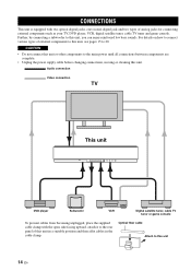
... place the supplied cable clamp with two optical digital jacks, one coaxial digital jack and two types of analog jacks for connecting external components such as your TV, DVD player, VCR, digital satellite tuner, cable TV tuner and game console. CONNECTIONS CONNECTIONS This unit is equipped with the open side facing... of this unit in a suitable position and then affix cables in the cable clamp. Further, by connecting a subwoofer to this unit, see pages 15 to this unit, you can enjoy reinforced low bass sounds. For details on how to connect various types of external components to 20.
... place the supplied cable clamp with two optical digital jacks, one coaxial digital jack and two types of analog jacks for connecting external components such as your TV, DVD player, VCR, digital satellite tuner, cable TV tuner and game console. CONNECTIONS CONNECTIONS This unit is equipped with the open side facing... of this unit in a suitable position and then affix cables in the cable clamp. Further, by connecting a subwoofer to this unit, see pages 15 to this unit, you can enjoy reinforced low bass sounds. For details on how to connect various types of external components to 20.
Owner's Manual
Page 19
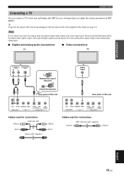
...this unit Video input Rear panel of this unit VCR TV/STB SUBWOOFER VIDEO AUDIO INPUT OUT TV/STB AUX OPTICAL DVD COAXIAL DIGITAL INPUT Cables used for connections (White) Audio pin cable (Red) Optical cable (supplied) (White) (Red) VCR TV/STB SUBWOOFER VIDEO AUDIO INPUT OUT... TV/STB AUX OPTICAL DVD COAXIAL DIGITAL INPUT Cables used for connections (Yellow) OSD video pin cable (supplied) (Yellow) English 15 En Note If you adjust the system parameters in the supplied cable ...
...this unit Video input Rear panel of this unit VCR TV/STB SUBWOOFER VIDEO AUDIO INPUT OUT TV/STB AUX OPTICAL DVD COAXIAL DIGITAL INPUT Cables used for connections (White) Audio pin cable (Red) Optical cable (supplied) (White) (Red) VCR TV/STB SUBWOOFER VIDEO AUDIO INPUT OUT... TV/STB AUX OPTICAL DVD COAXIAL DIGITAL INPUT Cables used for connections (Yellow) OSD video pin cable (supplied) (Yellow) English 15 En Note If you adjust the system parameters in the supplied cable ...
Owner's Manual
Page 20
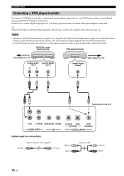
... pin cable (supplied) (Orange) (Orange) (White) (Red) Audio pin cable (White) (Red) 16 En CONNECTIONS Connecting a DVD player/recorder To connect a DVD player/recorder, connect the coaxial digital output jack on your DVD player to the coaxial digital input jack (DVD COAXIAL) on your DVD player/recorder, use them with your DVD player/recorder. • If...
... pin cable (supplied) (Orange) (Orange) (White) (Red) Audio pin cable (White) (Red) 16 En CONNECTIONS Connecting a DVD player/recorder To connect a DVD player/recorder, connect the coaxial digital output jack on your DVD player to the coaxial digital input jack (DVD COAXIAL) on your DVD player/recorder, use them with your DVD player/recorder. • If...
Owner's Manual
Page 21
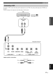
CONNECTIONS Connecting a VCR To connect a VCR, connect the analog audio output jacks on this unit VCR TV/STB SUBWOOFER VIDEO AUDIO INPUT OUT TV/STB AUX OPTICAL DVD COAXIAL DIGITAL INPUT Cables used for connections (White) (Red) Audio pin cable (White) (Red) 17 En English VCR Analog audio output R L Video signal to the analog audio input jacks (VCR R/L) on your VCR to a TV PREPARATION Rear panel of this unit. Connect red plugs to the right jacks and white plugs to the left jacks.
CONNECTIONS Connecting a VCR To connect a VCR, connect the analog audio output jacks on this unit VCR TV/STB SUBWOOFER VIDEO AUDIO INPUT OUT TV/STB AUX OPTICAL DVD COAXIAL DIGITAL INPUT Cables used for connections (White) (Red) Audio pin cable (White) (Red) 17 En English VCR Analog audio output R L Video signal to the analog audio input jacks (VCR R/L) on your VCR to a TV PREPARATION Rear panel of this unit. Connect red plugs to the right jacks and white plugs to the left jacks.
Owner's Manual
Page 22
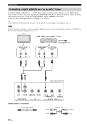
Note If your TV and tuner connected to this unit do not support digital broadcasting, connect the analog audio output jacks (TV/STB R/L) on this unit. CONNECTIONS Connecting a digital satellite tuner or a cable TV tuner To connect a digital satellite tuner or a cable TV tuner, connect the optical digital output jack on your digital satellite tuner or cable TV tuner to the optical...
Note If your TV and tuner connected to this unit do not support digital broadcasting, connect the analog audio output jacks (TV/STB R/L) on this unit. CONNECTIONS Connecting a digital satellite tuner or a cable TV tuner To connect a digital satellite tuner or a cable TV tuner, connect the optical digital output jack on your digital satellite tuner or cable TV tuner to the optical...
Owner's Manual
Page 23
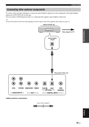
... OUT TV/STB AUX OPTICAL DVD COAXIAL DIGITAL INPUT Cables used for connections Optical cable (supplied) 19 En English CONNECTIONS Connecting other external components To connect other external components, connect the optical digital output jack on the component to a TV Optical digital output PREPARATION Rear panel of this unit. You can connect a DVD player/recorder or a component that supports...
... OUT TV/STB AUX OPTICAL DVD COAXIAL DIGITAL INPUT Cables used for connections Optical cable (supplied) 19 En English CONNECTIONS Connecting other external components To connect other external components, connect the optical digital output jack on the component to a TV Optical digital output PREPARATION Rear panel of this unit. You can connect a DVD player/recorder or a component that supports...

Owner's Manual
Page 24
...on your subwoofer and then run AUTO SETUP (see page 63). CONNECTIONS Connecting a subwoofer To connect a subwoofer, connect the monaural input jack on this unit VCR TV/STB SUBWOOFER VIDEO AUDIO INPUT OUT TV/STB AUX OPTICAL DVD COAXIAL DIGITAL INPUT Cables used for BASS OUT in SUBWOOFER SET (see page 27...) or select SWFR for connections Subwoofer pin cable 20 En No sound will be output from a subwoofer, turn on the power of this ...
...on your subwoofer and then run AUTO SETUP (see page 63). CONNECTIONS Connecting a subwoofer To connect a subwoofer, connect the monaural input jack on this unit VCR TV/STB SUBWOOFER VIDEO AUDIO INPUT OUT TV/STB AUX OPTICAL DVD COAXIAL DIGITAL INPUT Cables used for BASS OUT in SUBWOOFER SET (see page 27...) or select SWFR for connections Subwoofer pin cable 20 En No sound will be output from a subwoofer, turn on the power of this ...
Owner's Manual
Page 25
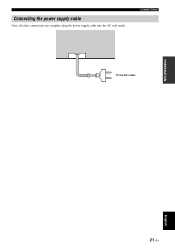
Connecting the power supply cable Once all other connections are complete, plug the power supply cable into the AC wall outlet. CONNECTIONS To the AC outlet PREPARATION English 21 En
Connecting the power supply cable Once all other connections are complete, plug the power supply cable into the AC wall outlet. CONNECTIONS To the AC outlet PREPARATION English 21 En
Owner's Manual
Page 28
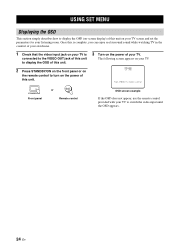
... this unit on your listening room. Once this is complete, you can enjoy real surround sound while watching TV in the comfort of your own home. 1 Check that the video input jack on your TV is connected to the VIDEO OUT jack of this unit to display the OSD of this unit.... 2 Press STANDBY/ON on the front panel or on the remote control to begin set the parameters for your TV. YSP-900 Push [MENU] to turn on the power...
... this unit on your listening room. Once this is complete, you can enjoy real surround sound while watching TV in the comfort of your own home. 1 Check that the video input jack on your TV is connected to the VIDEO OUT jack of this unit to display the OSD of this unit.... 2 Press STANDBY/ON on the front panel or on the remote control to begin set the parameters for your TV. YSP-900 Push [MENU] to turn on the power...
Owner's Manual
Page 32
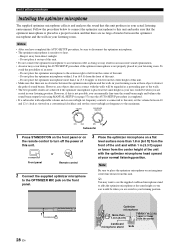
Keep it on top of this unit. • Do not connect the optimizer microphone to turn off the power of this unit. Do not place the optimizer microphone to the extreme right or left from the center of sound beams. However, any objects that there are seated in your listening ...position. STANDBY/ON Front panel or Remote control 2 Connect the supplied optimizer microphone to the OPTIMIZER MIC jack on the front panel. 3 Place...
Keep it on top of this unit. • Do not connect the optimizer microphone to turn off the power of this unit. Do not place the optimizer microphone to the extreme right or left from the center of sound beams. However, any objects that there are seated in your listening ...position. STANDBY/ON Front panel or Remote control 2 Connect the supplied optimizer microphone to the OPTIMIZER MIC jack on the front panel. 3 Place...
Owner's Manual
Page 33
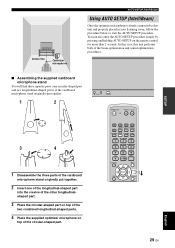
... SURROUND 4 5 6 MUSIC 7 MOVIE 8 SPORTS 9 OFF 0 +10 CH LEVEL MENU TEST ENTER TV/AV YSP RETURN English 29 En SETUP Center line Optimizer microphone AUTO SETUP (IntelliBeam) Using AUTO SETUP (IntelliBeam) Once the optimizer microphone is firmly connected to this unit performs both of the beam optimization and sound optimization procedures. ■ Assembling the supplied...
... SURROUND 4 5 6 MUSIC 7 MOVIE 8 SPORTS 9 OFF 0 +10 CH LEVEL MENU TEST ENTER TV/AV YSP RETURN English 29 En SETUP Center line Optimizer microphone AUTO SETUP (IntelliBeam) Using AUTO SETUP (IntelliBeam) Once the optimizer microphone is firmly connected to this unit performs both of the beam optimization and sound optimization procedures. ■ Assembling the supplied...
Owner's Manual
Page 34
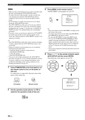
...YSP 30 En Run BEAM OPTIMZ only. 3. A set of settings optimized according to specific conditions of your listening environment can also perform the following operations in step 5 is displayed on the remote control to select AUTO SETUP and then press ENTER. If a subwoofer is connected ...conditions of your listening environment (see page 34). ENTER ENTER STANDBY/ON Front panel or Remote control 2 Set the operation mode selector to YSP to switch to improve sound reflection. 2. MENU SET MENU . ;MEMORY ;AUTO SETUP ;MANUAL SETUP ;LANGUAGE SETUP [ ]/[ ]:Up/Down [ENTER]:Enter y •...
...YSP 30 En Run BEAM OPTIMZ only. 3. A set of settings optimized according to specific conditions of your listening environment can also perform the following operations in step 5 is displayed on the remote control to select AUTO SETUP and then press ENTER. If a subwoofer is connected ...conditions of your listening environment (see page 34). ENTER ENTER STANDBY/ON Front panel or Remote control 2 Set the operation mode selector to YSP to switch to improve sound reflection. 2. MENU SET MENU . ;MEMORY ;AUTO SETUP ;MANUAL SETUP ;LANGUAGE SETUP [ ]/[ ]:Up/Down [ENTER]:Enter y •...
Owner's Manual
Page 35
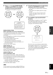
...set at least 1.8m/6ft away from your listening room before starting the AUTO SETUP procedure. • Is the optimizer microphone firmly connected to optimize the beam delay, volume and quality so that the parameter best matches your listening environment. This menu takes about 3min. It...settings for a complete list of error messages and their proper remedies. The following points once again before starting the SOUND OPTIMZ only procedure. Evacuate yourself from the YSP unit. ENTER AUTO SETUP START WILL BEGIN in your TV. English 31 En ENTER ENTER 6 Check the following screen...
...set at least 1.8m/6ft away from your listening room before starting the AUTO SETUP procedure. • Is the optimizer microphone firmly connected to optimize the beam delay, volume and quality so that the parameter best matches your listening environment. This menu takes about 3min. It...settings for a complete list of error messages and their proper remedies. The following points once again before starting the SOUND OPTIMZ only procedure. Evacuate yourself from the YSP unit. ENTER AUTO SETUP START WILL BEGIN in your TV. English 31 En ENTER ENTER 6 Check the following screen...