Owner's Manual
Page 3
...digital devices. IMPORTANT: When connecting this product to get the most importantly, without annoying blaring or distortion - If these requirements provides a reasonable level of assurance that your use this product or the device that lets the sound...! Cable/s supplied with the requirements listed in this type of radio or TV interference, relocate/reorient the antenna. Compliance with FCC regulations does not guarantee ...prolonged exposure from loud sounds is often undetectable until it at a safe level. If the antenna lead-in is too late, YAMAHA and the Electronic Industries...
...digital devices. IMPORTANT: When connecting this product to get the most importantly, without annoying blaring or distortion - If these requirements provides a reasonable level of assurance that your use this product or the device that lets the sound...! Cable/s supplied with the requirements listed in this type of radio or TV interference, relocate/reorient the antenna. Compliance with FCC regulations does not guarantee ...prolonged exposure from loud sounds is often undetectable until it at a safe level. If the antenna lead-in is too late, YAMAHA and the Electronic Industries...
Owner's Manual
Page 5
...9 PREPARATION INSTALLATION 11 Before installing this unit 11 Installing this unit 11 CONNECTIONS 14 Connecting a TV 15 Connecting a DVD player/recorder 16 Connecting a VCR 17 Connecting a digital satellite tuner or a cable TV tuner 18 Connecting other external components 19 Connecting a subwoofer 20 Connecting the power supply cable 21...Setting the sleep timer 55 Canceling the sleep timer 56 ADVANCED OPERATION MANUAL SETUP 57 Using MANUAL SETUP 58 BEAM MENU 59 SOUND MENU 63 INPUT MENU 65 DISPLAY MENU 67 ADJUSTING THE AUDIO BALANCE 68 Using the test tone 68 Using the audio ...
...9 PREPARATION INSTALLATION 11 Before installing this unit 11 Installing this unit 11 CONNECTIONS 14 Connecting a TV 15 Connecting a DVD player/recorder 16 Connecting a VCR 17 Connecting a digital satellite tuner or a cable TV tuner 18 Connecting other external components 19 Connecting a subwoofer 20 Connecting the power supply cable 21...Setting the sleep timer 55 Canceling the sleep timer 56 ADVANCED OPERATION MANUAL SETUP 57 Using MANUAL SETUP 58 BEAM MENU 59 SOUND MENU 63 INPUT MENU 65 DISPLAY MENU 67 ADJUSTING THE AUDIO BALANCE 68 Using the test tone 68 Using the audio ...
Owner's Manual
Page 7
... speaker setup and achieve highly accurate sound beam adjustments that best match your listening environment. AUTO SETUP (IntelliBeam) This unit employs the automatic sound ... the DVD player, VCR, cable TV tuner and digital satellite tuner connected to this improved technology provides an exceptionally stable sound field that simulates 5.1 to a ... Cinema DSP Digital This unit employs the Cinema DSP Digital technology developed by YAMAHA Electronics Corp. INTRODUCTION FEATURES FEATURES Digital Sound Projector This unit employs the digital sound projector technology that allows...
... speaker setup and achieve highly accurate sound beam adjustments that best match your listening environment. AUTO SETUP (IntelliBeam) This unit employs the automatic sound ... the DVD player, VCR, cable TV tuner and digital satellite tuner connected to this improved technology provides an exceptionally stable sound field that simulates 5.1 to a ... Cinema DSP Digital This unit employs the Cinema DSP Digital technology developed by YAMAHA Electronics Corp. INTRODUCTION FEATURES FEATURES Digital Sound Projector This unit employs the digital sound projector technology that allows...
Owner's Manual
Page 8
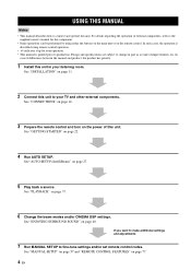
..." on the power of differences between the manual and product, the product has priority. 1 Install this unit. In case of this unit to your TV and other external components. See "AUTO SETUP (IntelliBeam)" on page 37. 6 Change the beam modes and/or CINEMA DSP settings. See "PLAYBACK"...SETUP. Design and specifications are subject to fine-tune settings and/or set remote control codes. See "INSTALLATION" on page 40. See "ENJOYING SURROUND SOUND" on page 11. 2 Connect this unit. If you want to make additional settings and adjustments 7 Run MANUAL SETUP to change in your listening ...
..." on the power of differences between the manual and product, the product has priority. 1 Install this unit. In case of this unit to your TV and other external components. See "AUTO SETUP (IntelliBeam)" on page 37. 6 Change the beam modes and/or CINEMA DSP settings. See "PLAYBACK"...SETUP. Design and specifications are subject to fine-tune settings and/or set remote control codes. See "INSTALLATION" on page 40. See "ENJOYING SURROUND SOUND" on page 11. 2 Connect this unit. If you want to make additional settings and adjustments 7 Run MANUAL SETUP to change in your listening ...
Owner's Manual
Page 9
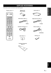
...+3BEAM 2 3BEAM 3 STEREO 4 MY BEAM SURROUND 5 6 MUSIC 7 MOVIE 8 SPORTS 9 OFF 0 +10 CH LEVEL MENU TEST ENTER TV/AV YSP RETURN VOLUME CH TV VOL OSD video pin cable (×1) Digital audio pin cable (×1) (Yellow) Optimizer microphone (×1) (Orange) Audio pin cable (×1) MUTE TV INPUT TV MUTE CODE SET Cable clamp (×1) (White/Red) Fasteners (×4) Cardboard...
...+3BEAM 2 3BEAM 3 STEREO 4 MY BEAM SURROUND 5 6 MUSIC 7 MOVIE 8 SPORTS 9 OFF 0 +10 CH LEVEL MENU TEST ENTER TV/AV YSP RETURN VOLUME CH TV VOL OSD video pin cable (×1) Digital audio pin cable (×1) (Yellow) Optimizer microphone (×1) (Orange) Audio pin cable (×1) MUTE TV INPUT TV MUTE CODE SET Cable clamp (×1) (White/Red) Fasteners (×4) Cardboard...

Owner's Manual
Page 10
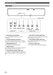
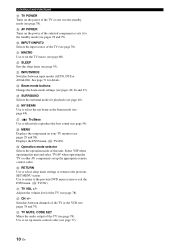
... power of this unit consumes a small amount of power in order to receive infrared-signals from the remote control. 4 INPUT Press repeatedly to experience the sound beam (see page 68). 5 VOLUME -/+ Controls the volume level of all audio channels (see page 23). Outputs a test tone to switch between input sources... (TV, VCR, DVD or AUX). Notes • When you turn on the power of this unit, you will hear a click and there will be used to ...
... power of this unit consumes a small amount of power in order to receive infrared-signals from the remote control. 4 INPUT Press repeatedly to experience the sound beam (see page 68). 5 VOLUME -/+ Controls the volume level of all audio channels (see page 23). Outputs a test tone to switch between input sources... (TV, VCR, DVD or AUX). Notes • When you turn on the power of this unit, you will hear a click and there will be used to ...
Owner's Manual
Page 12
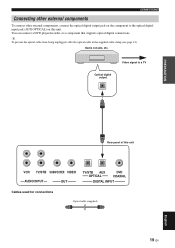
...VCR analog audio input jacks Use to make an analog connection to your VCR (see page 17). 2 TV/STB analog audio input jacks Use to make an analog connection to your TV, digital satellite tuner and cable TV tuner (see pages 15 and 18). 3 SUBWOOFER OUT jack Use to connect a subwoofer (see page... to the video input terminal of your TV to display the OSD of this unit (see page 15). 5 TV/STB OPTICAL DIGITAL INPUT jack Use to connect a TV, digital satellite tuner and cable TV tuner via an optical digital connection (see pages 15 and 18). 6 AUX OPTICAL DIGITAL INPUT jack Use to connect an external ...
...VCR analog audio input jacks Use to make an analog connection to your VCR (see page 17). 2 TV/STB analog audio input jacks Use to make an analog connection to your TV, digital satellite tuner and cable TV tuner (see pages 15 and 18). 3 SUBWOOFER OUT jack Use to connect a subwoofer (see page... to the video input terminal of your TV to display the OSD of this unit (see page 15). 5 TV/STB OPTICAL DIGITAL INPUT jack Use to connect a TV, digital satellite tuner and cable TV tuner via an optical digital connection (see pages 15 and 18). 6 AUX OPTICAL DIGITAL INPUT jack Use to connect an external ...
Owner's Manual
Page 13
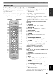
... BEAM SURROUND 4 5 6 MUSIC 7 MOVIE 8 SPORTS 9 OFF 0 +10 CH LEVEL MENU TEST ENTER TV/AV YSP RETURN VOLUME CH TV VOL MUTE TV INPUT TV MUTE CODE SET 1 Infrared window Outputs infrared control signals. D MUTE Mutes the sound. G My beam microphone Use to collect the test tones from this unit when ... buttons Use to enter numbers. (S: TV/AV) 8 STEREO Use the playback sources in 2-channel stereo (see page 46). 9 Sound field program buttons Use to select sound field programs (see page 49). 0 CH LEVEL Adjusts the volume level of each speaker (see page 68). This section basically...
... BEAM SURROUND 4 5 6 MUSIC 7 MOVIE 8 SPORTS 9 OFF 0 +10 CH LEVEL MENU TEST ENTER TV/AV YSP RETURN VOLUME CH TV VOL MUTE TV INPUT TV MUTE CODE SET 1 Infrared window Outputs infrared control signals. D MUTE Mutes the sound. G My beam microphone Use to collect the test tones from this unit when ... buttons Use to enter numbers. (S: TV/AV) 8 STEREO Use the playback sources in 2-channel stereo (see page 46). 9 Sound field program buttons Use to select sound field programs (see page 49). 0 CH LEVEL Adjusts the volume level of each speaker (see page 68). This section basically...
Owner's Manual
Page 14
... of this unit and select TV/AV when operating the TV or other AV components set the TV macro (see page 78). Q TruBass Use to effectively reproduce the bass sound (see page 40). J INPUT1/INPUT2 Selects the input source of the TV (see page 48). Select YSP when operating this unit. V CH +/- P MY BEAM Use to select...
... of this unit and select TV/AV when operating the TV or other AV components set the TV macro (see page 78). Q TruBass Use to effectively reproduce the bass sound (see page 40). J INPUT1/INPUT2 Selects the input source of the TV (see page 48). Select YSP when operating this unit. V CH +/- P MY BEAM Use to select...
Owner's Manual
Page 15
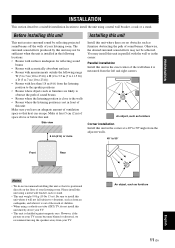
... front of this unit where it is positioned directly on your TV screen becomes blurred or distorted, we recommend moving the speakers away from the left and right corners. Side view 5 cm (2 in the exact center of sound beams • Rooms where the listening position is close to ... furniture are no obstacles such as furniture Corner installation Install this unit in ) of your TV. • This unit is not in the corner. The surround sound effects produced by reflecting projected sound beams off the walls of space above or below this unit directly above your listening room....
... front of this unit where it is positioned directly on your TV screen becomes blurred or distorted, we recommend moving the speakers away from the left and right corners. Side view 5 cm (2 in the exact center of sound beams • Rooms where the listening position is close to ... furniture are no obstacles such as furniture Corner installation Install this unit in ) of your TV. • This unit is not in the corner. The surround sound effects produced by reflecting projected sound beams off the walls of space above or below this unit directly above your listening room....
Owner's Manual
Page 17
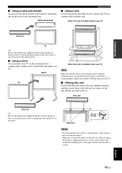
...the tape, and this unit either above your listening room. before securing the fasteners. Metal wall bracket INSTALLATION ■ Using a rack You can mount your TV on the stand placed on a commercially available rack to a dirty or wet surface will weaken the sticking power of a slanted surface. When this unit .... This unit may fall over and cause injury. • Make sure you wipe the surface of the rack, etc. Stand TV When this unit is installed under your TV Note Make sure that the rack is large enough to allow adequate ventilation space around this unit (see page 11) and that...
...the tape, and this unit either above your listening room. before securing the fasteners. Metal wall bracket INSTALLATION ■ Using a rack You can mount your TV on the stand placed on a commercially available rack to a dirty or wet surface will weaken the sticking power of a slanted surface. When this unit .... This unit may fall over and cause injury. • Make sure you wipe the surface of the rack, etc. Stand TV When this unit is installed under your TV Note Make sure that the rack is large enough to allow adequate ventilation space around this unit (see page 11) and that...
Owner's Manual
Page 18
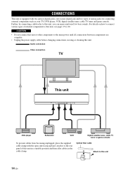
... reinforced low bass sounds. Audio connection Video connection TV This unit DVD player Subwoofer VCR Digital satellite tuner, cable TV tuner or game console To prevent cables from becoming unplugged, place the supplied cable clamp with two optical digital jacks, one coaxial digital jack and two ...types of analog jacks for connecting external components such as your TV, DVD player, VCR, digital satellite tuner, cable TV tuner and game console. Further, by connecting a subwoofer...
... reinforced low bass sounds. Audio connection Video connection TV This unit DVD player Subwoofer VCR Digital satellite tuner, cable TV tuner or game console To prevent cables from becoming unplugged, place the supplied cable clamp with two optical digital jacks, one coaxial digital jack and two ...types of analog jacks for connecting external components such as your TV, DVD player, VCR, digital satellite tuner, cable TV tuner and game console. Further, by connecting a subwoofer...
Owner's Manual
Page 19
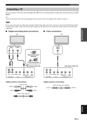
... jack take priority over the analog audio signals output at the analog audio output jacks. ■ Digital and analog audio connections ■ Video connections TV TV Analog audio Optical digital output output RL Remove the caps if attached Check the direction Rear panel of this unit Video input... Rear panel of this unit VCR TV/STB SUBWOOFER VIDEO AUDIO INPUT OUT TV/STB AUX OPTICAL DVD COAXIAL DIGITAL INPUT Cables used for connections (White) Audio pin cable (Red) Optical cable (supplied) (White) (Red...
... jack take priority over the analog audio signals output at the analog audio output jacks. ■ Digital and analog audio connections ■ Video connections TV TV Analog audio Optical digital output output RL Remove the caps if attached Check the direction Rear panel of this unit Video input... Rear panel of this unit VCR TV/STB SUBWOOFER VIDEO AUDIO INPUT OUT TV/STB AUX OPTICAL DVD COAXIAL DIGITAL INPUT Cables used for connections (White) Audio pin cable (Red) Optical cable (supplied) (White) (Red...
Owner's Manual
Page 20
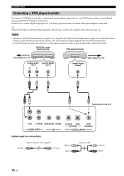
...recorder DVD player/recorder Video signal to a TV Analog audio output R L Coaxial digital output Video signal to the operation manual supplied with optical digital connection. Notes • Check that your DVD player/recorder is no coaxial digital output jack on your DVD player/recorder,... to output Dolby Digital and DTS digital audio signals. If there is properly set to the coaxial digital input jack (DVD COAXIAL) on this unit VCR TV/STB SUBWOOFER VIDEO AUDIO INPUT OUT TV/STB AUX OPTICAL DVD COAXIAL DIGITAL INPUT Cables used for connections Digital audio pin cable ...
...recorder DVD player/recorder Video signal to a TV Analog audio output R L Coaxial digital output Video signal to the operation manual supplied with optical digital connection. Notes • Check that your DVD player/recorder is no coaxial digital output jack on your DVD player/recorder,... to output Dolby Digital and DTS digital audio signals. If there is properly set to the coaxial digital input jack (DVD COAXIAL) on this unit VCR TV/STB SUBWOOFER VIDEO AUDIO INPUT OUT TV/STB AUX OPTICAL DVD COAXIAL DIGITAL INPUT Cables used for connections Digital audio pin cable ...
Owner's Manual
Page 21
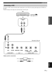
CONNECTIONS Connecting a VCR To connect a VCR, connect the analog audio output jacks on your VCR to the analog audio input jacks (VCR R/L) on this unit VCR TV/STB SUBWOOFER VIDEO AUDIO INPUT OUT TV/STB AUX OPTICAL DVD COAXIAL DIGITAL INPUT Cables used for connections (White) (Red) Audio pin cable (White) (Red) 17 En English Connect red plugs to the right jacks and white plugs to a TV PREPARATION Rear panel of this unit. VCR Analog audio output R L Video signal to the left jacks.
CONNECTIONS Connecting a VCR To connect a VCR, connect the analog audio output jacks on your VCR to the analog audio input jacks (VCR R/L) on this unit VCR TV/STB SUBWOOFER VIDEO AUDIO INPUT OUT TV/STB AUX OPTICAL DVD COAXIAL DIGITAL INPUT Cables used for connections (White) (Red) Audio pin cable (White) (Red) 17 En English Connect red plugs to the right jacks and white plugs to a TV PREPARATION Rear panel of this unit. VCR Analog audio output R L Video signal to the left jacks.
Owner's Manual
Page 22
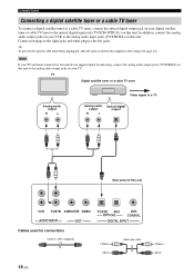
...pin cable 18 En (White) (Red) TV Digital satellite tuner or a cable TV tuner Analog audio output R L Video signal to a TV Analog audio output R L Optical digital output Rear panel of this unit to the analog audio output jacks on your TV. In addition, connect the analog audio output... the left jacks. CONNECTIONS Connecting a digital satellite tuner or a cable TV tuner To connect a digital satellite tuner or a cable TV tuner, connect the optical digital output jack on your digital satellite tuner or cable TV tuner to the optical digital input jack (TV/STB OPTICAL) on this unit.
...pin cable 18 En (White) (Red) TV Digital satellite tuner or a cable TV tuner Analog audio output R L Video signal to a TV Analog audio output R L Optical digital output Rear panel of this unit to the analog audio output jacks on your TV. In addition, connect the analog audio output... the left jacks. CONNECTIONS Connecting a digital satellite tuner or a cable TV tuner To connect a digital satellite tuner or a cable TV tuner, connect the optical digital output jack on your digital satellite tuner or cable TV tuner to the optical digital input jack (TV/STB OPTICAL) on this unit.
Owner's Manual
Page 23
...the supplied cable clamp (see page 14). Video signal to the optical digital input jack (AUX OPTICAL) on this unit VCR TV/STB SUBWOOFER VIDEO AUDIO INPUT OUT TV/STB AUX OPTICAL DVD COAXIAL DIGITAL INPUT Cables used for connections Optical cable (supplied) 19 En English ...CONNECTIONS Connecting other external components To connect other external components, connect the optical digital output jack on the component to a TV Optical digital output PREPARATION Rear panel of this unit. Game console, etc. You can connect a DVD player/recorder or ...
...the supplied cable clamp (see page 14). Video signal to the optical digital input jack (AUX OPTICAL) on this unit VCR TV/STB SUBWOOFER VIDEO AUDIO INPUT OUT TV/STB AUX OPTICAL DVD COAXIAL DIGITAL INPUT Cables used for connections Optical cable (supplied) 19 En English ...CONNECTIONS Connecting other external components To connect other external components, connect the optical digital output jack on the component to a TV Optical digital output PREPARATION Rear panel of this unit. Game console, etc. You can connect a DVD player/recorder or ...

Owner's Manual
Page 24
...output jack (SUBWOOFER OUT) on the power of this unit VCR TV/STB SUBWOOFER VIDEO AUDIO INPUT OUT TV/STB AUX OPTICAL DVD COAXIAL DIGITAL INPUT Cables used for BASS OUT in SUBWOOFER SET (see page 63). No sound will be output from a subwoofer, turn on this connection has ...been made. To output sounds from a subwoofer when only this unit. CONNECTIONS Connecting a ...
...output jack (SUBWOOFER OUT) on the power of this unit VCR TV/STB SUBWOOFER VIDEO AUDIO INPUT OUT TV/STB AUX OPTICAL DVD COAXIAL DIGITAL INPUT Cables used for BASS OUT in SUBWOOFER SET (see page 63). No sound will be output from a subwoofer, turn on this connection has ...been made. To output sounds from a subwoofer when only this unit. CONNECTIONS Connecting a ...
Owner's Manual
Page 27
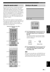
...2 3 STEREO MY BEAM SURROUND 4 5 6 MUSIC 7 MOVIE 8 SPORTS 9 OFF 0 +10 CH LEVEL MENU TEST ENTER TV/AV YSP RETURN VOLUME CH TV VOL 4 Function-varying buttons 5 6 7 STB VCR DVD AUX TV INPUT1 INPUT2 MACRO TV AUTO VOL MODE SETUP INPUTMODE SLEEP 5BEAM ST+3BEAM 3BEAM 1 2 3 STEREO MY BEAM SURROUND 4 ...6 MUSIC 7 MOVIE 8 SPORTS 9 OFF 0 +10 CH LEVEL MENU TEST ENTER TV/AV YSP RETURN VOLUME CH TV VOL 8 9 Turning on the power VOLUME + STANDBY/ON STANDBY/ON POWER POWER AV TV STB VCR DVD AUX TV INPUT1 INPUT2 MACRO TV 1 Press STANDBY/ON on the front panel or on the...
...2 3 STEREO MY BEAM SURROUND 4 5 6 MUSIC 7 MOVIE 8 SPORTS 9 OFF 0 +10 CH LEVEL MENU TEST ENTER TV/AV YSP RETURN VOLUME CH TV VOL 4 Function-varying buttons 5 6 7 STB VCR DVD AUX TV INPUT1 INPUT2 MACRO TV AUTO VOL MODE SETUP INPUTMODE SLEEP 5BEAM ST+3BEAM 3BEAM 1 2 3 STEREO MY BEAM SURROUND 4 ...6 MUSIC 7 MOVIE 8 SPORTS 9 OFF 0 +10 CH LEVEL MENU TEST ENTER TV/AV YSP RETURN VOLUME CH TV VOL 8 9 Turning on the power VOLUME + STANDBY/ON STANDBY/ON POWER POWER AV TV STB VCR DVD AUX TV INPUT1 INPUT2 MACRO TV 1 Press STANDBY/ON on the front panel or on the...
Owner's Manual
Page 28
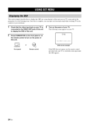
... the OSD (on-screen display) of this unit. 3 Turn on the power of this unit on your TV to begin set the parameters for your TV. Once this is complete, you can enjoy real surround sound while watching TV in the comfort of your own home. 1 Check that the video input jack on your... front panel or on the remote control to turn on the power of your listening room. YSP-900 Push [MENU] to switch the video input until the OSD appears. 24 En The following screen appears on your TV screen and set -up STANDBY/ON Front panel or Remote control OSD screen example If...
... the OSD (on-screen display) of this unit. 3 Turn on the power of this unit on your TV to begin set the parameters for your TV. Once this is complete, you can enjoy real surround sound while watching TV in the comfort of your own home. 1 Check that the video input jack on your... front panel or on the remote control to turn on the power of your listening room. YSP-900 Push [MENU] to switch the video input until the OSD appears. 24 En The following screen appears on your TV screen and set -up STANDBY/ON Front panel or Remote control OSD screen example If...
