Owner's Manual
Page 5
...14 Connecting a TV 15 Connecting a DVD player/recorder 16 Connecting a VCR 17 Connecting a digital satellite tuner or a cable TV tuner 18 Connecting other external components 19 Connecting a subwoofer 20 Connecting the power supply cable 21 SETUP GETTING STARTED 22 Installing batteries in the remote ... macro 80 BASIC OPERATION PLAYBACK 37 Selecting the input source 37 Playing back sources 38 Adjusting the volume 39 Muting the sound 39 ENJOYING SURROUND SOUND 40 5 beam 40 Stereo plus 3 beam 41 3 beam 41 ADDITIONAL INFORMATION TROUBLESHOOTING 82 GLOSSARY 85 Audio formats 85...
...14 Connecting a TV 15 Connecting a DVD player/recorder 16 Connecting a VCR 17 Connecting a digital satellite tuner or a cable TV tuner 18 Connecting other external components 19 Connecting a subwoofer 20 Connecting the power supply cable 21 SETUP GETTING STARTED 22 Installing batteries in the remote ... macro 80 BASIC OPERATION PLAYBACK 37 Selecting the input source 37 Playing back sources 38 Adjusting the volume 39 Muting the sound 39 ENJOYING SURROUND SOUND 40 5 beam 40 Stereo plus 3 beam 41 3 beam 41 ADDITIONAL INFORMATION TROUBLESHOOTING 82 GLOSSARY 85 Audio formats 85...
Owner's Manual
Page 7
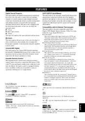
... macro capability so that you can achieve a clear sound in a surround sound experience. ◆ Dolby Pro Logic II This is fundamentally a redesigned version of Dolby Pro Logic that employs 2 stereo surround channels, a subwoofer and a greatly enhanced steering logic. The " "...on DVDs and other purely digital media. AUTO SETUP (IntelliBeam) This unit employs the automatic sound beam and acoustic optimization technology with the press of YAMAHA Corporation. INTRODUCTION FEATURES FEATURES Digital Sound Projector This unit employs the digital sound projector technology that allows one ...
... macro capability so that you can achieve a clear sound in a surround sound experience. ◆ Dolby Pro Logic II This is fundamentally a redesigned version of Dolby Pro Logic that employs 2 stereo surround channels, a subwoofer and a greatly enhanced steering logic. The " "...on DVDs and other purely digital media. AUTO SETUP (IntelliBeam) This unit employs the automatic sound beam and acoustic optimization technology with the press of YAMAHA Corporation. INTRODUCTION FEATURES FEATURES Digital Sound Projector This unit employs the digital sound projector technology that allows one ...
Owner's Manual
Page 12
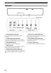
CONTROLS AND FUNCTIONS Rear panel 1 23 4 8 5 6 (Europe model) 7 VCR TV/STB SUBWOOFER VIDEO AUDIO INPUT OUT TV/STB AUX OPTICAL DVD COAXIAL DIGITAL INPUT 1 VCR analog audio input jacks Use to make an analog connection to your VCR (see page 17). 2 TV/STB analog audio input jacks Use ...to make an analog connection to your TV, digital satellite tuner and cable TV tuner (see pages 15 and 18). 3 SUBWOOFER OUT jack Use to connect a subwoofer (see page 20). 4 VIDEO OUT jack Use to connect to the video input terminal of your TV...
CONTROLS AND FUNCTIONS Rear panel 1 23 4 8 5 6 (Europe model) 7 VCR TV/STB SUBWOOFER VIDEO AUDIO INPUT OUT TV/STB AUX OPTICAL DVD COAXIAL DIGITAL INPUT 1 VCR analog audio input jacks Use to make an analog connection to your VCR (see page 17). 2 TV/STB analog audio input jacks Use ...to make an analog connection to your TV, digital satellite tuner and cable TV tuner (see pages 15 and 18). 3 SUBWOOFER OUT jack Use to connect a subwoofer (see page 20). 4 VIDEO OUT jack Use to connect to the video input terminal of your TV...
Owner's Manual
Page 18
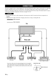
... supply cable before changing connections, moving or cleaning this unit. Further, by connecting a subwoofer to 20. For details on how to connect various types of analog jacks for connecting external components... such as your TV, DVD player, VCR, digital satellite tuner, cable TV tuner and game console. CONNECTIONS CONNECTIONS This unit is equipped ...in the cable clamp. Audio connection Video connection TV This unit DVD player Subwoofer VCR Digital satellite tuner, cable TV tuner or game console To prevent cables from becoming unplugged, ...
... supply cable before changing connections, moving or cleaning this unit. Further, by connecting a subwoofer to 20. For details on how to connect various types of analog jacks for connecting external components... such as your TV, DVD player, VCR, digital satellite tuner, cable TV tuner and game console. CONNECTIONS CONNECTIONS This unit is equipped ...in the cable clamp. Audio connection Video connection TV This unit DVD player Subwoofer VCR Digital satellite tuner, cable TV tuner or game console To prevent cables from becoming unplugged, ...
Owner's Manual
Page 19
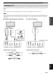
...connect a TV to this unit and display the OSD for easy viewing when you connect this unit VCR TV/STB SUBWOOFER VIDEO AUDIO INPUT OUT TV/STB AUX OPTICAL DVD COAXIAL DIGITAL INPUT Cables used for connections (White) Audio pin cable (Red) Optical cable (supplied) (White) (Red) ...VCR TV/STB SUBWOOFER VIDEO AUDIO INPUT OUT TV/STB AUX OPTICAL DVD COAXIAL DIGITAL INPUT Cables used for connections (Yellow) OSD video pin cable (supplied) (Yellow) English 15 En Note If you ...
...connect a TV to this unit and display the OSD for easy viewing when you connect this unit VCR TV/STB SUBWOOFER VIDEO AUDIO INPUT OUT TV/STB AUX OPTICAL DVD COAXIAL DIGITAL INPUT Cables used for connections (White) Audio pin cable (Red) Optical cable (supplied) (White) (Red) ...VCR TV/STB SUBWOOFER VIDEO AUDIO INPUT OUT TV/STB AUX OPTICAL DVD COAXIAL DIGITAL INPUT Cables used for connections (Yellow) OSD video pin cable (supplied) (Yellow) English 15 En Note If you ...
Owner's Manual
Page 20
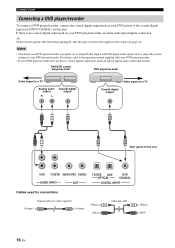
... Video signal to a TV Analog audio output R L Coaxial digital output Video signal to a TV Coaxial digital output Rear panel of your DVD player/recorder is no coaxial digital output jack on this unit VCR TV/STB SUBWOOFER VIDEO AUDIO INPUT OUT TV/STB AUX OPTICAL DVD COAXIAL... DIGITAL INPUT Cables used for connections Digital audio pin cable (supplied) (Orange) (Orange) (White) (Red) Audio pin cable (White...
... Video signal to a TV Analog audio output R L Coaxial digital output Video signal to a TV Coaxial digital output Rear panel of your DVD player/recorder is no coaxial digital output jack on this unit VCR TV/STB SUBWOOFER VIDEO AUDIO INPUT OUT TV/STB AUX OPTICAL DVD COAXIAL... DIGITAL INPUT Cables used for connections Digital audio pin cable (supplied) (Orange) (Orange) (White) (Red) Audio pin cable (White...
Owner's Manual
Page 21
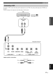
VCR Analog audio output R L Video signal to the analog audio input jacks (VCR R/L) on your VCR to a TV PREPARATION Rear panel of this unit. CONNECTIONS Connecting a VCR To connect a VCR, connect the analog audio output jacks on this unit VCR TV/STB SUBWOOFER VIDEO AUDIO INPUT OUT TV/STB AUX OPTICAL DVD COAXIAL DIGITAL INPUT Cables used for connections (White) (Red) Audio pin cable (White) (Red) 17 En English Connect red plugs to the right jacks and white plugs to the left jacks.
VCR Analog audio output R L Video signal to the analog audio input jacks (VCR R/L) on your VCR to a TV PREPARATION Rear panel of this unit. CONNECTIONS Connecting a VCR To connect a VCR, connect the analog audio output jacks on this unit VCR TV/STB SUBWOOFER VIDEO AUDIO INPUT OUT TV/STB AUX OPTICAL DVD COAXIAL DIGITAL INPUT Cables used for connections (White) (Red) Audio pin cable (White) (Red) 17 En English Connect red plugs to the right jacks and white plugs to the left jacks.
Owner's Manual
Page 22
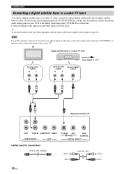
... to this unit do not support digital broadcasting, connect the analog audio output jacks (TV/STB R/L) on this unit to the analog audio output jacks on this unit. In addition, connect the analog audio output jacks on this unit VCR TV/STB SUBWOOFER VIDEO AUDIO INPUT OUT TV/STB ...AUX OPTICAL DVD COAXIAL DIGITAL INPUT Cables used for connections Optical cable (supplied) (White) (Red) Audio pin cable 18 En (White) (Red) ...
... to this unit do not support digital broadcasting, connect the analog audio output jacks (TV/STB R/L) on this unit to the analog audio output jacks on this unit. In addition, connect the analog audio output jacks on this unit VCR TV/STB SUBWOOFER VIDEO AUDIO INPUT OUT TV/STB ...AUX OPTICAL DVD COAXIAL DIGITAL INPUT Cables used for connections Optical cable (supplied) (White) (Red) Audio pin cable 18 En (White) (Red) ...
Owner's Manual
Page 23
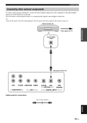
... can connect a DVD player/recorder or a component that supports optical digital connections. Game console, etc. Video signal to the optical digital input jack (AUX OPTICAL) on this unit VCR TV/STB SUBWOOFER VIDEO AUDIO INPUT OUT TV/STB AUX OPTICAL DVD COAXIAL DIGITAL INPUT Cables used for connections Optical cable (supplied) 19 En English...
... can connect a DVD player/recorder or a component that supports optical digital connections. Game console, etc. Video signal to the optical digital input jack (AUX OPTICAL) on this unit VCR TV/STB SUBWOOFER VIDEO AUDIO INPUT OUT TV/STB AUX OPTICAL DVD COAXIAL DIGITAL INPUT Cables used for connections Optical cable (supplied) 19 En English...

Owner's Manual
Page 24
... the monaural input jack on your subwoofer and then run AUTO SETUP (see page 27) or select SWFR for connections Subwoofer pin cable 20 En To output sounds from a subwoofer when only this unit VCR TV/STB SUBWOOFER VIDEO AUDIO INPUT OUT TV/STB AUX OPTICAL DVD COAXIAL DIGITAL INPUT Cables used for BASS OUT in...
... the monaural input jack on your subwoofer and then run AUTO SETUP (see page 27) or select SWFR for connections Subwoofer pin cable 20 En To output sounds from a subwoofer when only this unit VCR TV/STB SUBWOOFER VIDEO AUDIO INPUT OUT TV/STB AUX OPTICAL DVD COAXIAL DIGITAL INPUT Cables used for BASS OUT in...

Owner's Manual
Page 31
Just as you would arrange the speaker position of other audio systems, you to provide highly precise automatic adjustment of frequency characteristics. LEVEL: Checks and adjusts the sound output level of each sound beam reaches the listening position at the same time. The... if BEAM OPTIMZ only is selected. *3 The subwoofer checking procedure is skipped if BEAM OPTIMZ only is selected. *2 *3 Checking the subwoofer Optimizing the beam delay, frequency and volume Sound optimization SETUP English 27 En The sound optimization feature incorporates three parameters (frequency, level and...
Just as you would arrange the speaker position of other audio systems, you to provide highly precise automatic adjustment of frequency characteristics. LEVEL: Checks and adjusts the sound output level of each sound beam reaches the listening position at the same time. The... if BEAM OPTIMZ only is selected. *3 The subwoofer checking procedure is skipped if BEAM OPTIMZ only is selected. *2 *3 Checking the subwoofer Optimizing the beam delay, frequency and volume Sound optimization SETUP English 27 En The sound optimization feature incorporates three parameters (frequency, level and...
Owner's Manual
Page 32
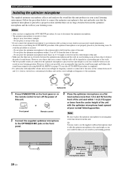
..., if this is not possible, you can manually fine-tune the sound beam angle and balance the sound beam output levels using MANUAL SETUP (see page 57) once the AUTO SETUP procedure is completed. • If a subwoofer with adjustable volume and crossover/high cut frequency to the OPTIMIZER MIC ... and the walls in your listening room. To avoid the possibility of this unit. - VOLUME CROSSOVER HIGH CUT MIN MAX MIN MAX Subwoofer 1 Press STANDBY/ON on the front panel or on a conventional clockface and set the volume between the optimizer microphone and the walls ...
..., if this is not possible, you can manually fine-tune the sound beam angle and balance the sound beam output levels using MANUAL SETUP (see page 57) once the AUTO SETUP procedure is completed. • If a subwoofer with adjustable volume and crossover/high cut frequency to the OPTIMIZER MIC ... and the walls in your listening room. To avoid the possibility of this unit. - VOLUME CROSSOVER HIGH CUT MIN MAX MIN MAX Subwoofer 1 Press STANDBY/ON on the front panel or on a conventional clockface and set the volume between the optimizer microphone and the walls ...
Owner's Manual
Page 34
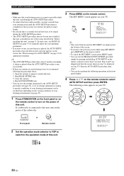
...8226; You can be run MANUAL SETUP (see page 35). 1 Press STANDBY/ON on the front panel or on page 33 for appropriate remedies. If a subwoofer is connected to this unit. AUTO SETUP (IntelliBeam) p p p p Notes • Make sure that you may not be recalled later depending on the ... of this unit" on the power of the rooms described in "Before installing this unit. ;AUTO SETUP . 1)BEAM+SOUND OPTIMZ 2)BEAM OPTIMZ only 3)SOUND OPTIMZ only [ ]/[ ]:Up/Down [ENTER]:Enter TV/AV YSP 30 En Start the AUTO SETUP procedure from your listening environment (see page 57) to improve...
...8226; You can be run MANUAL SETUP (see page 35). 1 Press STANDBY/ON on the front panel or on page 33 for appropriate remedies. If a subwoofer is connected to this unit. AUTO SETUP (IntelliBeam) p p p p Notes • Make sure that you may not be recalled later depending on the ... of this unit" on the power of the rooms described in "Before installing this unit. ;AUTO SETUP . 1)BEAM+SOUND OPTIMZ 2)BEAM OPTIMZ only 3)SOUND OPTIMZ only [ ]/[ ]:Up/Down [ENTER]:Enter TV/AV YSP 30 En Start the AUTO SETUP procedure from your listening environment (see page 57) to improve...

Owner's Manual
Page 36
...left and right may not be set up . 10 Disconnect the optimizer microphone from the YSP and the listening position. OPTIMIZER MIC Example 2 SHOW RESULT MEASUREMENT COMPLETE ENVIRONMENT CHECK[FAILED] BEAM MODE :5 BEAM SUBWOOFER :YES [ENTER]:Save set-up. [RETURN]:Do not save set -up. For ...MEASUREMENT COMPLETE BEAM MODE :5 BEAM SUBWOOFER :NOT APPLICABLE [ENTER]:Save set-up. [RETURN]:Do not save set -up correctly. If ''ENVIRONMENT CHECK [FAILED]'' is displayed in "Error messages for 2 seconds and then disappears from step 3. AUTO SETUP COMPLETE Your YSP unit may be set to the...
...left and right may not be set up . 10 Disconnect the optimizer microphone from the YSP and the listening position. OPTIMIZER MIC Example 2 SHOW RESULT MEASUREMENT COMPLETE ENVIRONMENT CHECK[FAILED] BEAM MODE :5 BEAM SUBWOOFER :YES [ENTER]:Save set-up. [RETURN]:Do not save set -up. For ...MEASUREMENT COMPLETE BEAM MODE :5 BEAM SUBWOOFER :NOT APPLICABLE [ENTER]:Save set-up. [RETURN]:Do not save set -up correctly. If ''ENVIRONMENT CHECK [FAILED]'' is displayed in "Error messages for 2 seconds and then disappears from step 3. AUTO SETUP COMPLETE Your YSP unit may be set to the...
Owner's Manual
Page 51
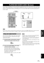
... in the remote control may be reflected on the walls in a single channel. TV/AV YSP 2 Press and hold MY BEAM on the remote control collects the test tones from the subwoofer connected to be week if the remote control does not function properly. Control range: L50°...POWER AV TV 5BEAM ST+3BEAM 3BEAM 1 2 3 STEREO MY BEAM SURROUND 4 5 6 MUSIC 7 MOVIE 8 SPORTS 9 OFF 0 +10 CH LEVEL MENU TEST ENTER TV/AV YSP RETURN Note If the my beam is noisy. PLAYING BACK SOUND CLEARLY (MY BEAM) PLAYING BACK SOUND CLEARLY (My beam) You can collect the test tones.
... in the remote control may be reflected on the walls in a single channel. TV/AV YSP 2 Press and hold MY BEAM on the remote control collects the test tones from the subwoofer connected to be week if the remote control does not function properly. Control range: L50°...POWER AV TV 5BEAM ST+3BEAM 3BEAM 1 2 3 STEREO MY BEAM SURROUND 4 5 6 MUSIC 7 MOVIE 8 SPORTS 9 OFF 0 +10 CH LEVEL MENU TEST ENTER TV/AV YSP RETURN Note If the my beam is noisy. PLAYING BACK SOUND CLEARLY (MY BEAM) PLAYING BACK SOUND CLEARLY (My beam) You can collect the test tones.
Owner's Manual
Page 58
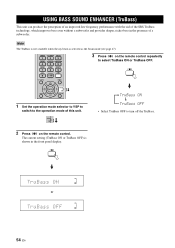
...SOUND ENHANCER (TRUBASS) USING BASS SOUND ENHANCER (TruBass) This unit can produce the perception of an improved low frequency performance with the aid of the SRS TruBass technology, which improves bass even without a subwoofer and provides deeper, richer bass in the front panel display. TEST ENTER TV/AV YSP... to the operation mode of a subwoofer. The current setting (TruBass ON or TruBass OFF) is selected as the beam mode (see page 47). 5BEAM ST+3BEAM 3BEAM 1 2 3 STEREO MY BEAM SURROUND 4 5 6 MUSIC 7 MOVIE 8 SPORTS 9 OFF 0 +10 CH LEVEL MENU 3 Press on the remote...
...SOUND ENHANCER (TRUBASS) USING BASS SOUND ENHANCER (TruBass) This unit can produce the perception of an improved low frequency performance with the aid of the SRS TruBass technology, which improves bass even without a subwoofer and provides deeper, richer bass in the front panel display. TEST ENTER TV/AV YSP... to the operation mode of a subwoofer. The current setting (TruBass ON or TruBass OFF) is selected as the beam mode (see page 47). 5BEAM ST+3BEAM 3BEAM 1 2 3 STEREO MY BEAM SURROUND 4 5 6 MUSIC 7 MOVIE 8 SPORTS 9 OFF 0 +10 CH LEVEL MENU 3 Press on the remote...

Owner's Manual
Page 61
...subwoofer settings. 63 MUTE LEVEL Adjusts the muting level. 64 AUDIO DELAY Adjusts audio delay. 64 ROOM EQ Adjusts the tonal quality of the listening room. 64 DD/DTS Dynamic Range Adjusts the dynamic range of the front left and right channels. IMAGE LOCATION Adjusts the sound position of Dolby Digital...(indicated in bold under each parameter) to the sound beam output. Use SOUND MENU and BEAM MENU to make additional adjustments. • BEAM MENU allows you to make settings for the surround sound effects normally available in the speaker settings menu. • Make settings for the...
...subwoofer settings. 63 MUTE LEVEL Adjusts the muting level. 64 AUDIO DELAY Adjusts audio delay. 64 ROOM EQ Adjusts the tonal quality of the listening room. 64 DD/DTS Dynamic Range Adjusts the dynamic range of the front left and right channels. IMAGE LOCATION Adjusts the sound position of Dolby Digital...(indicated in bold under each parameter) to the sound beam output. Use SOUND MENU and BEAM MENU to make additional adjustments. • BEAM MENU allows you to make settings for the surround sound effects normally available in the speaker settings menu. • Make settings for the...
Owner's Manual
Page 67
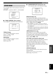
... [ ]/[ ]:Up/Down [ ]/[ ]:Sel [ENTER]:Return BASS OUT (Bass out) Low-frequency (bass) signals can be sent to the subwoofer speaker position. LFE and low-frequency signals from other channels are directed to adjust the low frequency response. Choices: 80Hz, 100Hz, 120Hz LFE LEVEL ... also determines the routing of the sound beams. A)TONE CONTROL - + . TREBLE;;;;;0dB ------ - + BASS;;;;;;;0dB ------ Choices: SWFR (subwoofer), FRONT • Select SWFR if you can adjust the tonal quality of LFE (low-frequency effect) signals found in Dolby Digital or DTS sources. LFE and low...
... [ ]/[ ]:Up/Down [ ]/[ ]:Sel [ENTER]:Return BASS OUT (Bass out) Low-frequency (bass) signals can be sent to the subwoofer speaker position. LFE and low-frequency signals from other channels are directed to adjust the low frequency response. Choices: 80Hz, 100Hz, 120Hz LFE LEVEL ... also determines the routing of the sound beams. A)TONE CONTROL - + . TREBLE;;;;;0dB ------ - + BASS;;;;;;;0dB ------ Choices: SWFR (subwoofer), FRONT • Select SWFR if you can adjust the tonal quality of LFE (low-frequency effect) signals found in Dolby Digital or DTS sources. LFE and low...

Owner's Manual
Page 72
... TEST SUR.R TEST SUR.L 1 Set the operation mode selector to YSP to switch to manually balance the channel levels. TV/AV YSP TEST SWFR Note TEST SWFR is only available when a subwoofer is selected for BASS OUT in SOUND MENU (see page 63). 2 Press TEST on the remote control. ENTER VOL TEST FRONT L... Control range: -10 dB to this unit. Use the test tone to adjust. OFF 0 CH LEVEL +10 MENU...
... TEST SUR.R TEST SUR.L 1 Set the operation mode selector to YSP to switch to manually balance the channel levels. TV/AV YSP TEST SWFR Note TEST SWFR is only available when a subwoofer is selected for BASS OUT in SOUND MENU (see page 63). 2 Press TEST on the remote control. ENTER VOL TEST FRONT L... Control range: -10 dB to this unit. Use the test tone to adjust. OFF 0 CH LEVEL +10 MENU...

Owner's Manual
Page 74
...dB to +10 dB 4 Wait for BASS OUT in the front panel display. 70 En ADJUSTING THE AUDIO BALANCE Note SWFR is only available when a subwoofer is connected to adjust channel volumes. Notes • All the channel levels cannot be adjusted when the stereo playback is selected as the beam mode... cannot be adjusted when the stereo plus 3 is selected as the beam mode (see page 41). • Only CENTER can be adjusted, - -dB appears in SOUND MENU (see page 63). 3 Press / to this unit and SWFR is selected as the beam mode (see page 47). • FRONT L/R are automatically adjusted depending...
...dB to +10 dB 4 Wait for BASS OUT in the front panel display. 70 En ADJUSTING THE AUDIO BALANCE Note SWFR is only available when a subwoofer is connected to adjust channel volumes. Notes • All the channel levels cannot be adjusted when the stereo playback is selected as the beam mode... cannot be adjusted when the stereo plus 3 is selected as the beam mode (see page 41). • Only CENTER can be adjusted, - -dB appears in SOUND MENU (see page 63). 3 Press / to this unit and SWFR is selected as the beam mode (see page 47). • FRONT L/R are automatically adjusted depending...


