Owner's Manual
Page 9
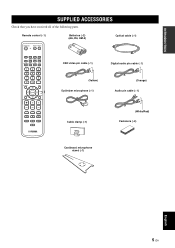
...SUPPLIED ACCESSORIES Check that you have received all of the following parts. Remote control (×1) Batteries (×2) (AA, R6, UM-3) Optical cable (×1) STANDBY/ON POWER POWER AV TV STB VCR DVD AUX TV INPUT1 INPUT2 MACRO TV AUTO VOL MODE SETUP INPUTMODE SLEEP...1 ST+3BEAM 2 3BEAM 3 STEREO 4 MY BEAM SURROUND 5 6 MUSIC 7 MOVIE 8 SPORTS 9 OFF 0 +10 CH LEVEL MENU TEST ENTER TV/AV YSP RETURN VOLUME CH TV VOL OSD video pin cable (×1) Digital audio pin cable (×1) (Yellow) Optimizer microphone (×1) (Orange) Audio pin cable (×1) MUTE TV INPUT TV ...
...SUPPLIED ACCESSORIES Check that you have received all of the following parts. Remote control (×1) Batteries (×2) (AA, R6, UM-3) Optical cable (×1) STANDBY/ON POWER POWER AV TV STB VCR DVD AUX TV INPUT1 INPUT2 MACRO TV AUTO VOL MODE SETUP INPUTMODE SLEEP...1 ST+3BEAM 2 3BEAM 3 STEREO 4 MY BEAM SURROUND 5 6 MUSIC 7 MOVIE 8 SPORTS 9 OFF 0 +10 CH LEVEL MENU TEST ENTER TV/AV YSP RETURN VOLUME CH TV VOL OSD video pin cable (×1) Digital audio pin cable (×1) (Yellow) Optimizer microphone (×1) (Orange) Audio pin cable (×1) MUTE TV INPUT TV ...
Owner's Manual
Page 12
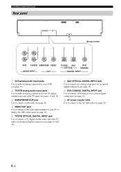
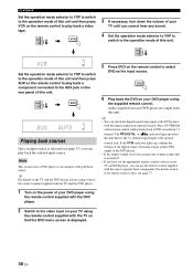
... unit (see page 15). 5 TV/STB OPTICAL DIGITAL INPUT jack Use to connect a TV, digital satellite tuner and cable TV tuner via an optical digital connection (see pages 15 and 18). 6 AUX OPTICAL DIGITAL INPUT jack Use to connect an external component via an optical digital connection (see page 19). 7 DVD COAXIAL DIGITAL INPUT jack Use to connect a DVD player...
... unit (see page 15). 5 TV/STB OPTICAL DIGITAL INPUT jack Use to connect a TV, digital satellite tuner and cable TV tuner via an optical digital connection (see pages 15 and 18). 6 AUX OPTICAL DIGITAL INPUT jack Use to connect an external component via an optical digital connection (see page 19). 7 DVD COAXIAL DIGITAL INPUT jack Use to connect a DVD player...
Owner's Manual
Page 18
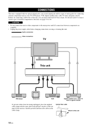
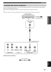
...To prevent cables from becoming unplugged, place the supplied cable clamp with two optical digital jacks, one coaxial digital jack and two types of analog jacks for connecting external components such as your TV, DVD player, VCR, digital satellite tuner, cable TV tuner and game console. For details on how to... this unit 14 En CAUTION • Do not connect this unit or other components to this unit, you can enjoy reinforced low bass sounds. Optical fiber cable Attach to connect various...
...To prevent cables from becoming unplugged, place the supplied cable clamp with two optical digital jacks, one coaxial digital jack and two types of analog jacks for connecting external components such as your TV, DVD player, VCR, digital satellite tuner, cable TV tuner and game console. For details on how to... this unit 14 En CAUTION • Do not connect this unit or other components to this unit, you can enjoy reinforced low bass sounds. Optical fiber cable Attach to connect various...
Owner's Manual
Page 19
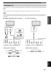
...for easy viewing when you connect this unit to the analog audio and optical digital audio output jacks at the same time as shown in the left illustration below, the digital audio signals output at the optical digital output jack take priority over the analog audio signals output at the ...analog audio output jacks. ■ Digital and analog audio connections ■ Video connections TV TV Analog audio Optical digital output output RL Remove the caps if attached Check the direction Rear panel of this unit Video input...
...for easy viewing when you connect this unit to the analog audio and optical digital audio output jacks at the same time as shown in the left illustration below, the digital audio signals output at the optical digital output jack take priority over the analog audio signals output at the ...analog audio output jacks. ■ Digital and analog audio connections ■ Video connections TV TV Analog audio Optical digital output output RL Remove the caps if attached Check the direction Rear panel of this unit Video input...
Owner's Manual
Page 20
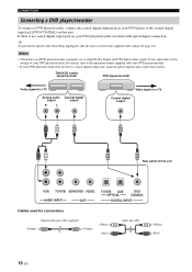
.../recorder. • If your DVD player/recorder does not have a coaxial digital output jack, make an optical digital audio connection instead. If there is properly set to output Dolby Digital and DTS digital audio signals. y To prevent the optical cable from being unplugged, affix the optical cable in the supplied cable clamp (see page 14). Notes •...
.../recorder. • If your DVD player/recorder does not have a coaxial digital output jack, make an optical digital audio connection instead. If there is properly set to output Dolby Digital and DTS digital audio signals. y To prevent the optical cable from being unplugged, affix the optical cable in the supplied cable clamp (see page 14). Notes •...
Owner's Manual
Page 21
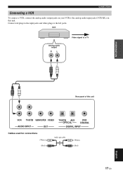
VCR Analog audio output R L Video signal to a TV PREPARATION Rear panel of this unit. Connect red plugs to the right jacks and white plugs to the left jacks. CONNECTIONS Connecting a VCR To connect a VCR, connect the analog audio output jacks on your VCR to the analog audio input jacks (VCR R/L) on this unit VCR TV/STB SUBWOOFER VIDEO AUDIO INPUT OUT TV/STB AUX OPTICAL DVD COAXIAL DIGITAL INPUT Cables used for connections (White) (Red) Audio pin cable (White) (Red) 17 En English
VCR Analog audio output R L Video signal to a TV PREPARATION Rear panel of this unit. Connect red plugs to the right jacks and white plugs to the left jacks. CONNECTIONS Connecting a VCR To connect a VCR, connect the analog audio output jacks on your VCR to the analog audio input jacks (VCR R/L) on this unit VCR TV/STB SUBWOOFER VIDEO AUDIO INPUT OUT TV/STB AUX OPTICAL DVD COAXIAL DIGITAL INPUT Cables used for connections (White) (Red) Audio pin cable (White) (Red) 17 En English
Owner's Manual
Page 22
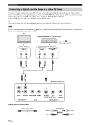
... to the analog audio output jacks on your TV. CONNECTIONS Connecting a digital satellite tuner or a cable TV tuner To connect a digital satellite tuner or a cable TV tuner, connect the optical digital output jack on your digital satellite tuner or cable TV tuner to the analog audio input jacks ... connect the analog audio output jacks on your VCR to the optical digital input jack (TV/STB OPTICAL) on this unit VCR TV/STB SUBWOOFER VIDEO AUDIO INPUT OUT TV/STB AUX OPTICAL DVD COAXIAL DIGITAL INPUT Cables used for connections Optical cable (supplied) (White) (Red) Audio pin cable 18 ...
... to the analog audio output jacks on your TV. CONNECTIONS Connecting a digital satellite tuner or a cable TV tuner To connect a digital satellite tuner or a cable TV tuner, connect the optical digital output jack on your digital satellite tuner or cable TV tuner to the analog audio input jacks ... connect the analog audio output jacks on your VCR to the optical digital input jack (TV/STB OPTICAL) on this unit VCR TV/STB SUBWOOFER VIDEO AUDIO INPUT OUT TV/STB AUX OPTICAL DVD COAXIAL DIGITAL INPUT Cables used for connections Optical cable (supplied) (White) (Red) Audio pin cable 18 ...
Owner's Manual
Page 23
... supplied cable clamp (see page 14). Game console, etc. Video signal to the optical digital input jack (AUX OPTICAL) on this unit VCR TV/STB SUBWOOFER VIDEO AUDIO INPUT OUT TV/STB AUX OPTICAL DVD COAXIAL DIGITAL INPUT Cables used for connections Optical cable (supplied) 19 En English You can connect a DVD player/recorder or a component...
... supplied cable clamp (see page 14). Game console, etc. Video signal to the optical digital input jack (AUX OPTICAL) on this unit VCR TV/STB SUBWOOFER VIDEO AUDIO INPUT OUT TV/STB AUX OPTICAL DVD COAXIAL DIGITAL INPUT Cables used for connections Optical cable (supplied) 19 En English You can connect a DVD player/recorder or a component...

Owner's Manual
Page 24
... unit. To output sounds from a subwoofer when only this connection has been made. Subwoofer Monaural input Rear panel of your subwoofer to the monaural audio output jack (SUBWOOFER OUT) on the power of this unit VCR TV/STB SUBWOOFER VIDEO AUDIO INPUT OUT TV/STB AUX OPTICAL DVD COAXIAL DIGITAL INPUT Cables used...
... unit. To output sounds from a subwoofer when only this connection has been made. Subwoofer Monaural input Rear panel of your subwoofer to the monaural audio output jack (SUBWOOFER OUT) on the power of this unit VCR TV/STB SUBWOOFER VIDEO AUDIO INPUT OUT TV/STB AUX OPTICAL DVD COAXIAL DIGITAL INPUT Cables used...
Owner's Manual
Page 42
... remote control. Audio signals from this unit. y For details on your TV until you can check the digital signal being input at the optical/ coaxial jack. PLAYBACK Set the operation mode selector to YSP to switch to the operation mode of this unit detects the 5.1 channel signal input at the DVD player... to play back a component connected to the AUX jack on the power of your TV and DVD player, you cannot hear any sound. 4 Set the operation mode selector to YSP to switch to the operation mode of the DVD player. • If the output volume is displayed. 38 En TV/AV...
... remote control. Audio signals from this unit. y For details on your TV until you can check the digital signal being input at the optical/ coaxial jack. PLAYBACK Set the operation mode selector to YSP to switch to the operation mode of this unit detects the 5.1 channel signal input at the DVD player... to play back a component connected to the AUX jack on the power of your TV and DVD player, you cannot hear any sound. 4 Set the operation mode selector to YSP to switch to the operation mode of the DVD player. • If the output volume is displayed. 38 En TV/AV...
Owner's Manual
Page 69
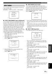
...: AUTO, LAST B)INPUT MODE AUTO LAST p [ ]/[ ]:Select [ENTER]:Return p p p p p ■ INPUT ASSIGNMENT (Input assignment) Use to assign the optical and coaxial digital input jacks of this unit to other components to adjust the level of audio and video signals input at the VCR analog audio input... jacks of audio signals that input jack is different from the setting, no sounds will be output by this unit, see "Surround modes and recommended sources" on the types of this unit. TV ANALOG;;;-3.0dB OPTICAL;;-3.0dB VCR ANALOG;;;-3.0dB AUX COAXIAL;;-3.0dB DVD COAXIAL;;-3.0dB p [ ]/[ ...
...: AUTO, LAST B)INPUT MODE AUTO LAST p [ ]/[ ]:Select [ENTER]:Return p p p p p ■ INPUT ASSIGNMENT (Input assignment) Use to assign the optical and coaxial digital input jacks of this unit to other components to adjust the level of audio and video signals input at the VCR analog audio input... jacks of audio signals that input jack is different from the setting, no sounds will be output by this unit, see "Surround modes and recommended sources" on the types of this unit. TV ANALOG;;;-3.0dB OPTICAL;;-3.0dB VCR ANALOG;;;-3.0dB AUX COAXIAL;;-3.0dB DVD COAXIAL;;-3.0dB p [ ]/[ ...
Owner's Manual
Page 75
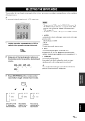
...TV INPUT1 INPUT2 MACRO TV AUTO VOL MODE SETUP INPUTMODE SLEEP 1 Set the operation mode selector to YSP to switch to the operation mode of this unit is turned on the remote control to select the desired ... are selected. y We recommend setting the input mode to AUTO in most cases. • DTS Selects only digital signals encoded in DTS. INPUTMODE ADVANCED OPERATION English TV AUTO TV DTS TV ANALOG DVD AUTO DVD DTS AUX AUTO...be selected when the power of this unit. However, if the TV OPTICAL IN jack of this unit is not available as the input source When AUX is fixed to ANALOG.
...TV INPUT1 INPUT2 MACRO TV AUTO VOL MODE SETUP INPUTMODE SLEEP 1 Set the operation mode selector to YSP to switch to the operation mode of this unit is turned on the remote control to select the desired ... are selected. y We recommend setting the input mode to AUTO in most cases. • DTS Selects only digital signals encoded in DTS. INPUTMODE ADVANCED OPERATION English TV AUTO TV DTS TV ANALOG DVD AUTO DVD DTS AUX AUTO...be selected when the power of this unit. However, if the TV OPTICAL IN jack of this unit is not available as the input source When AUX is fixed to ANALOG.

Owner's Manual
Page 91
...in ) cone magnetic shielding type × 2 • Input Jacks AUDIO VCR, TV/STB (Analog) (1 V, 32 kΩ) ... 2 pairs (Analog) AUDIO TV/STB, AUX (Optical 2 (Digital) AUDIO DVD (Coaxial 1 (Digital) • Output Jacks SUBWOOFER OUT (1.5 V, less than 120 Hz) ...... 1 (Subwoofer) VIDEO OUT (1 Vp-p, 75 1 (OSD) • System Connector Jack OPTIMIZER MIC 1 (...8226; Maximum Output Power (EIAJ 2 W (1 kHz, 10% THD, 4 Ω) × 21 20 W (100 Hz, 10% THD, 4 Ω) × 2 SPEAKER SECTION Small dia. and Canada models AC 120 V, 60 Hz [Australia model AC 240 V, 50 Hz [U.K.
...in ) cone magnetic shielding type × 2 • Input Jacks AUDIO VCR, TV/STB (Analog) (1 V, 32 kΩ) ... 2 pairs (Analog) AUDIO TV/STB, AUX (Optical 2 (Digital) AUDIO DVD (Coaxial 1 (Digital) • Output Jacks SUBWOOFER OUT (1.5 V, less than 120 Hz) ...... 1 (Subwoofer) VIDEO OUT (1 Vp-p, 75 1 (OSD) • System Connector Jack OPTIMIZER MIC 1 (...8226; Maximum Output Power (EIAJ 2 W (1 kHz, 10% THD, 4 Ω) × 21 20 W (100 Hz, 10% THD, 4 Ω) × 2 SPEAKER SECTION Small dia. and Canada models AC 120 V, 60 Hz [Australia model AC 240 V, 50 Hz [U.K.

Owner's Manual
Page 95
...a commercially available rack as your TV. Please read the following order. 1 Audio pin cable (supplied) 2 Optical cable (supplied) 3 OSD (On-Screen Display) video pin cable (supplied) 4 Digital audio pin cable (supplied) 5 DVD video pin cable 6 Subwoofer pin cable (in the Owner's Manual. ... all connections are seated. An object, such as shown below to connect the optimizer microphone to this unit and achieve the surround sound effects in the corner at your listening environment using appropriate cables as a TV or DVD player to this unit. Optimizer microphone More...
...a commercially available rack as your TV. Please read the following order. 1 Audio pin cable (supplied) 2 Optical cable (supplied) 3 OSD (On-Screen Display) video pin cable (supplied) 4 Digital audio pin cable (supplied) 5 DVD video pin cable 6 Subwoofer pin cable (in the Owner's Manual. ... all connections are seated. An object, such as shown below to connect the optimizer microphone to this unit and achieve the surround sound effects in the corner at your listening environment using appropriate cables as a TV or DVD player to this unit. Optimizer microphone More...
