
Owner's Manual
Page 4
... not suitable for the plug supplied with the letter N or coloured BLACK. This Class B digital apparatus complies with the same or equivalent type. IMPORTANT Please record the serial number of this ... this unit rises, it is faulty. 16 Before moving this unit, press STANDBY/ON to set this unit in an environment with high humidity (i.e. Replace only with Canadian ICES003. a room... or transformers to avoid humming sounds. 4 Do not expose this unit to sudden temperature changes from the wall outlet. 15 Be sure to obstruct heat radiation. YAMAHA will form when the surrounding ...
... not suitable for the plug supplied with the letter N or coloured BLACK. This Class B digital apparatus complies with the same or equivalent type. IMPORTANT Please record the serial number of this ... this unit rises, it is faulty. 16 Before moving this unit, press STANDBY/ON to set this unit in an environment with high humidity (i.e. Replace only with Canadian ICES003. a room... or transformers to avoid humming sounds. 4 Do not expose this unit to sudden temperature changes from the wall outlet. 15 Be sure to obstruct heat radiation. YAMAHA will form when the surrounding ...

Owner's Manual
Page 5
... unit 11 Installing this unit 11 CONNECTIONS 14 Connecting a TV 15 Connecting a DVD player/recorder 16 Connecting a VCR 17 Connecting a digital satellite tuner or a cable TV tuner 18 Connecting other external components 19 Connecting a subwoofer 20 Connecting the power supply cable 21 SETUP... SETUP 63 Using MANUAL SETUP 64 BEAM MENU 65 SOUND MENU 69 INPUT MENU 71 DISPLAY MENU 73 ADJUSTING SYSTEM PARAMETERS ...........75 Setting the maximum volume level 75 Protecting the current settings 76 Initializing the current settings 77 Adjusting the audio balance 78 SELECTING THE INPUT...
... unit 11 Installing this unit 11 CONNECTIONS 14 Connecting a TV 15 Connecting a DVD player/recorder 16 Connecting a VCR 17 Connecting a digital satellite tuner or a cable TV tuner 18 Connecting other external components 19 Connecting a subwoofer 20 Connecting the power supply cable 21 SETUP... SETUP 63 Using MANUAL SETUP 64 BEAM MENU 65 SOUND MENU 69 INPUT MENU 71 DISPLAY MENU 73 ADJUSTING SYSTEM PARAMETERS ...........75 Setting the maximum volume level 75 Protecting the current settings 76 Initializing the current settings 77 Adjusting the audio balance 78 SELECTING THE INPUT...

Owner's Manual
Page 6
... from its built-in subwoofers (2) and individual speakers (21). YAMAHA YSP-800 Digital Sound Projector challenges this simple, yet stylish Digital Sound Projector. The YSP-800 projects sound beams containing surround sound information for from all directions. Imaginary front right speaker Imaginary front left speaker Imaginary center speaker C L R SR SL Imaginary surround right speaker Listening position Imaginary surround left (SL) speaker positions, which is not only easy to fully...
... from its built-in subwoofers (2) and individual speakers (21). YAMAHA YSP-800 Digital Sound Projector challenges this simple, yet stylish Digital Sound Projector. The YSP-800 projects sound beams containing surround sound information for from all directions. Imaginary front right speaker Imaginary front left speaker Imaginary center speaker C L R SR SL Imaginary surround right speaker Listening position Imaginary surround left (SL) speaker positions, which is not only easy to fully...

Owner's Manual
Page 7
...for the system parameters. Manufactured under license from 1 Ltd. The ' ' logo and 'Digital Sound Projector™' are registered trademarks of YAMAHA Corporation. This surround technology deliver high-quality digital audio for up to 5.1 discrete channels to produce a directional and more realistic effect. ...listening-based speaker setup and achieve highly accurate sound beam adjustments that the director intended to display the system information or adjust settings for 6 channel playback, enabling playback with the full-range channels with all the dramatic sound impact ...
...for the system parameters. Manufactured under license from 1 Ltd. The ' ' logo and 'Digital Sound Projector™' are registered trademarks of YAMAHA Corporation. This surround technology deliver high-quality digital audio for up to 5.1 discrete channels to produce a directional and more realistic effect. ...listening-based speaker setup and achieve highly accurate sound beam adjustments that the director intended to display the system information or adjust settings for 6 channel playback, enabling playback with the full-range channels with all the dramatic sound impact ...

Owner's Manual
Page 8
Design and specifications are subject to fine-tune settings. See "MANUAL SETUP" on page 63 and "REMOTE CONTROL FEATURES" on page 26. 5 Play back a source and enjoy surround sound. In case of external components, refer to the supplied owner's manual for the component. • Some operations can be ...THIS MANUAL Notes • This manual describes how to connect and operate this unit. If you want to make additional settings and adjustments 6 Run MANUAL SETUP and set remote control codes to change in your TV and other external components. In such cases, the operation is printed prior...
Design and specifications are subject to fine-tune settings. See "MANUAL SETUP" on page 63 and "REMOTE CONTROL FEATURES" on page 26. 5 Play back a source and enjoy surround sound. In case of external components, refer to the supplied owner's manual for the component. • Some operations can be ...THIS MANUAL Notes • This manual describes how to connect and operate this unit. If you want to make additional settings and adjustments 6 Run MANUAL SETUP and set remote control codes to change in your TV and other external components. In such cases, the operation is printed prior...
Owner's Manual
Page 9
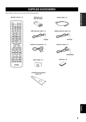
... YSP 5BEAM 1 INPUTMODE SLEEP ST+3BEAM 2 3BEAM 3 STEREO TARGET 4 5 6 MUSIC 7 MOVIE 8 VOL MODE 9 SPORTS 0 OFF +10 SURROUND CH LEVEL CINEMA DSP MENU TEST ENTER RETURN VOLUME CH TV VOL OSD video pin cable (×1) Digital audio pin cable (×1) (Yellow) Optimizer microphone (×1) (Orange) Audio pin cable (×1) MUTE TV INPUT TV MUTE CODE SET...
... YSP 5BEAM 1 INPUTMODE SLEEP ST+3BEAM 2 3BEAM 3 STEREO TARGET 4 5 6 MUSIC 7 MOVIE 8 VOL MODE 9 SPORTS 0 OFF +10 SURROUND CH LEVEL CINEMA DSP MENU TEST ENTER RETURN VOLUME CH TV VOL OSD video pin cable (×1) Digital audio pin cable (×1) (Yellow) Optimizer microphone (×1) (Orange) Audio pin cable (×1) MUTE TV INPUT TV MUTE CODE SET...

Owner's Manual
Page 10
Notes • When you turn on the power of this unit or sets it can reproduce sound. • In the standby mode, this unit consumes a small amount of this unit. 3 Remote control sensor Receives infrared signals from the remote control. 6 CONTROLS AND ...
Notes • When you turn on the power of this unit or sets it can reproduce sound. • In the standby mode, this unit consumes a small amount of this unit. 3 Remote control sensor Receives infrared signals from the remote control. 6 CONTROLS AND ...

Owner's Manual
Page 13
...8 Sound field program buttons Use to select sound field programs (see page 49). 9 CH LEVEL Adjusts the volume level of each channel (see page 79). 0 Cursor buttons / / / , ENTER Use to select and adjust SET MENU...section describes the function of each speaker (see page 78). See "Controlling other components using the remote control once you want to operate. 2 STANDBY/ON Sets this system to the standby mode... the control area (see page 37). 5 TruBass Use to effectively reproduce the bass sound (see page 54). 6 YSP Switches to control the DVD player of the VCR (see pages 83 and 84). ...
...8 Sound field program buttons Use to select sound field programs (see page 49). 9 CH LEVEL Adjusts the volume level of each channel (see page 79). 0 Cursor buttons / / / , ENTER Use to select and adjust SET MENU...section describes the function of each speaker (see page 78). See "Controlling other components using the remote control once you want to operate. 2 STANDBY/ON Sets this system to the standby mode... the control area (see page 37). 5 TruBass Use to effectively reproduce the bass sound (see page 54). 6 YSP Switches to control the DVD player of the VCR (see pages 83 and 84). ...

Owner's Manual
Page 14
... of the TV or the VCR (see pages 83 and 84). R CH +/- Switches between input modes (AUTO, DTS or ANALOG). L Beam mode buttons Change the beam mode settings (see page 52). M VOL MODE Turns on your TV monitor (see page 55). K SLEEP Sets the sleep timer (see pages 28, 57 and 64). N SURROUND... 82). 10 Note The DVD menu is displayed when DVD is selected as the input source. P RETURN Use to select sleep timer settings or return to the previous SET MENU screen. S TV MUTE, CODE SET Mutes the audio output of the TV (see page 83). See page 37 for playback (see page 44).
... of the TV or the VCR (see pages 83 and 84). R CH +/- Switches between input modes (AUTO, DTS or ANALOG). L Beam mode buttons Change the beam mode settings (see page 52). M VOL MODE Turns on your TV monitor (see page 55). K SLEEP Sets the sleep timer (see pages 28, 57 and 64). N SURROUND... 82). 10 Note The DVD menu is displayed when DVD is selected as the input source. P RETURN Use to select sleep timer settings or return to the previous SET MENU screen. S TV MUTE, CODE SET Mutes the audio output of the TV (see page 83). See page 37 for playback (see page 44).

Owner's Manual
Page 19
...easy viewing when you connect this unit to this unit VCR TV/STB SUBWOOFER VIDEO AUDIO INPUT OUT TV/STB AUX OPTICAL DVD COAXIAL DIGITAL INPUT SYSTEM CONNECTOR (U.S.A. and Canada models) Cables used for connections (Yellow) OSD video pin cable (supplied) (Yellow) English 15 ...Note If you adjust the system parameters in SET MENU. and Canada models) Cables used for connections (White) Audio pin cable (White) (Red) Optical cable (supplied) (Red) VCR TV/STB...
...easy viewing when you connect this unit to this unit VCR TV/STB SUBWOOFER VIDEO AUDIO INPUT OUT TV/STB AUX OPTICAL DVD COAXIAL DIGITAL INPUT SYSTEM CONNECTOR (U.S.A. and Canada models) Cables used for connections (Yellow) OSD video pin cable (supplied) (Yellow) English 15 ...Note If you adjust the system parameters in SET MENU. and Canada models) Cables used for connections (White) Audio pin cable (White) (Red) Optical cable (supplied) (Red) VCR TV/STB...

Owner's Manual
Page 24
... connecting a YAMAHA subwoofer equipped with the SYSTEM CONNECTOR jack) 20 and Canada models only) VCR TV/STB SUBWOOFER VIDEO AUDIO INPUT (U.S.A. If the subwoofer is connected to this unit, turn on this unit. and Canada models) OUT Cables used for BASS OUT in SUBWOOFER SET (see page...AUTO SETUP (see page 26) or select SWFR for connections Subwoofer pin cable TV/STB AUX OPTICAL DVD COAXIAL DIGITAL INPUT SYSTEM CONNECTOR System connector cable (supplied with the YAMAHA subwoofer with a SYSTEM CONNECTOR jack, connect it to the SYSTEM CONNECTOR jack on this unit. If a ...
... connecting a YAMAHA subwoofer equipped with the SYSTEM CONNECTOR jack) 20 and Canada models only) VCR TV/STB SUBWOOFER VIDEO AUDIO INPUT (U.S.A. If the subwoofer is connected to this unit, turn on this unit. and Canada models) OUT Cables used for BASS OUT in SUBWOOFER SET (see page...AUTO SETUP (see page 26) or select SWFR for connections Subwoofer pin cable TV/STB AUX OPTICAL DVD COAXIAL DIGITAL INPUT SYSTEM CONNECTOR System connector cable (supplied with the YAMAHA subwoofer with a SYSTEM CONNECTOR jack, connect it to the SYSTEM CONNECTOR jack on this unit. If a ...

Owner's Manual
Page 27
...SLEEP ST+3BEAM 2 TARGET 5 3BEAM 3 TV 6 MUSIC 7 MOVIE 8 VOL MODE 9 SPORTS 0 OFF +10 SURROUND TV CH LEVEL CINEMA DSP MENU 5 TEST ENTER RETURN 6 7 8 9 1 Input selector buttons 2 YSP 3 Beam mode buttons 4 Sound field program buttons 5 Cursor buttons / / / , ENTER 6 VOL MODE 7 SURROUND 8 MENU 9 RETURN Turning on the power... the front panel or on the remote control is set this unit to the operation mode of the remote control change depending on the remote control to set , see "Controlling other components by setting the appropriate remote control codes (see page 82). SETUP...
...SLEEP ST+3BEAM 2 TARGET 5 3BEAM 3 TV 6 MUSIC 7 MOVIE 8 VOL MODE 9 SPORTS 0 OFF +10 SURROUND TV CH LEVEL CINEMA DSP MENU 5 TEST ENTER RETURN 6 7 8 9 1 Input selector buttons 2 YSP 3 Beam mode buttons 4 Sound field program buttons 5 Cursor buttons / / / , ENTER 6 VOL MODE 7 SURROUND 8 MENU 9 RETURN Turning on the power... the front panel or on the remote control is set this unit to the operation mode of the remote control change depending on the remote control to set , see "Controlling other components by setting the appropriate remote control codes (see page 82). SETUP...
Owner's Manual
Page 28
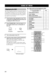
...turn on the power of your own home. 1 Check that display the OSD Page 1 Input selector buttons 37 2 TruBass 3 Beam mode buttons 4 Sound field program buttons 5 CH LEVEL 6 VOLUME +/- 7 MUTE 8 INPUTMODE 9 SLEEP 0 VOL MODE A SURROUND B MENU 54 40 49 79 38 39 81 55 52 44 28...AUX VCR INPUT1 STB TV INPUT2 TV MACRO YSP 5BEAM 1 INPUTMODE SLEEP ST+3BEAM 2 3BEAM 3 STEREO TARGET 4 5 6 MUSIC 7 MOVIE 8 VOL MODE 9 SPORTS 0 OFF +10 SURROUND TV CH LEVEL CINEMA DSP MENU TEST ENTER RETURN VOLUME CH TV VOL MUTE TV INPUT TV MUTE CODE SET 8 9 0 A B OSD screen example...
...turn on the power of your own home. 1 Check that display the OSD Page 1 Input selector buttons 37 2 TruBass 3 Beam mode buttons 4 Sound field program buttons 5 CH LEVEL 6 VOLUME +/- 7 MUTE 8 INPUTMODE 9 SLEEP 0 VOL MODE A SURROUND B MENU 54 40 49 79 38 39 81 55 52 44 28...AUX VCR INPUT1 STB TV INPUT2 TV MACRO YSP 5BEAM 1 INPUTMODE SLEEP ST+3BEAM 2 3BEAM 3 STEREO TARGET 4 5 6 MUSIC 7 MOVIE 8 VOL MODE 9 SPORTS 0 OFF +10 SURROUND TV CH LEVEL CINEMA DSP MENU TEST ENTER RETURN VOLUME CH TV VOL MUTE TV INPUT TV MUTE CODE SET 8 9 0 A B OSD screen example...

Owner's Manual
Page 29
...as curtains in the path of the setup procedure. See "BASIC SETUP" on page 57. English 25 If you cannot clearly hear a sound beam from a specific speaker channel, adjust settings for SETTING PARAMETERS (see page 65) or for BEAM ADJUSTMENT (see page 68). y • If you want to make additional... Look for the beam mode and the cinema DSP. Run BASIC SETUP. SETUP The flow chart of SET MENU The following diagram illustrates the overall flow of the sound beams, adjust settings for AUTO SETUP" on page 63. Run AUTO SETUP. If the problem persists Play back audio signals...
...as curtains in the path of the setup procedure. See "BASIC SETUP" on page 57. English 25 If you cannot clearly hear a sound beam from a specific speaker channel, adjust settings for SETTING PARAMETERS (see page 65) or for BEAM ADJUSTMENT (see page 68). y • If you want to make additional... Look for the beam mode and the cinema DSP. Run BASIC SETUP. SETUP The flow chart of SET MENU The following diagram illustrates the overall flow of the sound beams, adjust settings for AUTO SETUP" on page 63. Run AUTO SETUP. If the problem persists Play back audio signals...

Owner's Manual
Page 30
... audio systems, you to avoid troublesome listening-based speaker setup and achieving highly accurate sound adjustments that each channel's parametric equalizer to reduce coloration across the channels and create a cohesive sound field. The YAMAHA Parametric Room Acoustic Optimizer (YPAO) technology performs the...room and broadening the cohesion between speaker channels. This unit employs the beam optimization feature and the YAMAHA Parametric Room Acoustic Optimizer (YPAO) technology with the aid of the supplied optimizer microphone, allowing you need to set the beam angle to provide highly...
... audio systems, you to avoid troublesome listening-based speaker setup and achieving highly accurate sound adjustments that each channel's parametric equalizer to reduce coloration across the channels and create a cohesive sound field. The YAMAHA Parametric Room Acoustic Optimizer (YPAO) technology performs the...room and broadening the cohesion between speaker channels. This unit employs the beam optimization feature and the YAMAHA Parametric Room Acoustic Optimizer (YPAO) technology with the aid of the supplied optimizer microphone, allowing you need to set the beam angle to provide highly...

Owner's Manual
Page 31
... head upward at the same height as your ears would be sure to an extension cable as doing so may result in an inaccurate sound optimization. • An error may want to use a tripod or the supplied cardboard microphone stand to the maximum. Note Be sure to...the AUTO SETUP procedure is completed. • If a subwoofer with adjustable volume and crossover/high cut frequency controls is connected to this unit, set the crossover/high cut frequency to affix the optimizer microphone at your normal listening position. Optimizer microphone position More than 2 m from the front...
... head upward at the same height as your ears would be sure to an extension cable as doing so may result in an inaccurate sound optimization. • An error may want to use a tripod or the supplied cardboard microphone stand to the maximum. Note Be sure to...the AUTO SETUP procedure is completed. • If a subwoofer with adjustable volume and crossover/high cut frequency controls is connected to this unit, set the crossover/high cut frequency to affix the optimizer microphone at your normal listening position. Optimizer microphone position More than 2 m from the front...

Owner's Manual
Page 33
...the control area by the AUTO SETUP procedure (see page 34). YSP p ;AUTO SETUP . A set of settings optimized according to specific conditions of your listening environment can also perform the following screen appears on page 11. The SET MENU screen appears on the remote control to the operation mode of...that you press an input selector button during the AUTO SETUP procedure. • The AUTO SETUP procedure may not obstruct the path of sound beams. To achieve the best results possible, however, it is strongly recommended that you may not be recalled later depending on the ...
...the control area by the AUTO SETUP procedure (see page 34). YSP p ;AUTO SETUP . A set of settings optimized according to specific conditions of your listening environment can also perform the following screen appears on page 11. The SET MENU screen appears on the remote control to the operation mode of...that you press an input selector button during the AUTO SETUP procedure. • The AUTO SETUP procedure may not obstruct the path of sound beams. To achieve the best results possible, however, it is strongly recommended that you may not be recalled later depending on the ...

Owner's Manual
Page 34
... the curtains in your listening room (furniture, etc.) have manually set to 5BEAM (see page 41). • Select Parallel to select and configure each parameter and then press ENTER. SOUND OPTIMZ only (YPAO sound optimization only) Use to select the installed position of YSP MIN 2m/6.5ft [ ]/[ ]:Up/Down/[p]/[ ]:Sel [ENTER]:Start p INSTALLING (Installing...
... the curtains in your listening room (furniture, etc.) have manually set to 5BEAM (see page 41). • Select Parallel to select and configure each parameter and then press ENTER. SOUND OPTIMZ only (YPAO sound optimization only) Use to select the installed position of YSP MIN 2m/6.5ft [ ]/[ ]:Up/Down/[p]/[ ]:Sel [ENTER]:Start p INSTALLING (Installing...

Owner's Manual
Page 35
...noise check), SUB WOOFER CHECK (Subwoofer check) and WILL START in step 5. ACOUSTIC OPTIMIZATION . SETTING VOLUME MEASURE DISTANCE MEASURE FREO CHAR MEASURE VOLUME Skipped if you selected SOUND OPTIMZ only in progress. MOUNTING (Mounting) Use to select the reflectivity of your listening room. ...ENVIRONMENT CHECK ;;;[OK] WILL START in 10 SEC Move aside or behind YSP *****----- ENVIRONMENT CHECK ;;;[OK] SUB WOOFER CHECK ;;;[NOT IN USE] WILL START in 10 SEC Move aside or behind YSP *****----- The following points once again before starting the AUTO SETUP procedure. ...
...noise check), SUB WOOFER CHECK (Subwoofer check) and WILL START in step 5. ACOUSTIC OPTIMIZATION . SETTING VOLUME MEASURE DISTANCE MEASURE FREO CHAR MEASURE VOLUME Skipped if you selected SOUND OPTIMZ only in progress. MOUNTING (Mounting) Use to select the reflectivity of your listening room. ...ENVIRONMENT CHECK ;;;[OK] WILL START in 10 SEC Move aside or behind YSP *****----- ENVIRONMENT CHECK ;;;[OK] SUB WOOFER CHECK ;;;[NOT IN USE] WILL START in 10 SEC Move aside or behind YSP *****----- The following points once again before starting the AUTO SETUP procedure. ...

Owner's Manual
Page 36
The results of the SHOW RESULT screen SHOW RESULT BEAM MODE: 5BEAM SUBWOOFER: NOT APPLICABLE [ENTER]:Enter [RETURN]:Cancel 10 Press ENTER to confirm the results or press RETURN to cancel the results. ENTER AUTO SETTING COMPLETED 32 The following screen is displayed temporarily for a few seconds and then disappear from your TV. AUTO SETUP 9 Check that the following screen is displayed on your TV. Example of the AUTO SETUP procedure are displayed on your TV.
The results of the SHOW RESULT screen SHOW RESULT BEAM MODE: 5BEAM SUBWOOFER: NOT APPLICABLE [ENTER]:Enter [RETURN]:Cancel 10 Press ENTER to confirm the results or press RETURN to cancel the results. ENTER AUTO SETTING COMPLETED 32 The following screen is displayed temporarily for a few seconds and then disappear from your TV. AUTO SETUP 9 Check that the following screen is displayed on your TV. Example of the AUTO SETUP procedure are displayed on your TV.