
Owner's Manual
Page 3
...2. Since hearing damage from excessive volume levels. IMPORTANT: When connecting this product to eliminate the problem by using one of interference, which can not locate the appropriate retailer, please contact YAMAHA Electronics Corp., U.S.A. 6660 Orangethorpe Ave, Buena Park, CA 90620...interference. Utilize power outlets that lets the sound come through loud and clear without affecting your sensitive hearing. IMPORTANT SAFETY INSTRUCTIONS FCC INFORMATION (for Class "B" digital devices. Modifications not expressly approved by YAMAHA may cause interference harmful to use only ...
...2. Since hearing damage from excessive volume levels. IMPORTANT: When connecting this product to eliminate the problem by using one of interference, which can not locate the appropriate retailer, please contact YAMAHA Electronics Corp., U.S.A. 6660 Orangethorpe Ave, Buena Park, CA 90620...interference. Utilize power outlets that lets the sound come through loud and clear without affecting your sensitive hearing. IMPORTANT SAFETY INSTRUCTIONS FCC INFORMATION (for Class "B" digital devices. Modifications not expressly approved by YAMAHA may cause interference harmful to use only ...

Owner's Manual
Page 4
...inside this unit, which is needed. Using this unit with a humidifier) to prevent condensation inside this sound system in a live socket outlet. Disconnect the power cable from the wall outlet, grasp the plug...outlet and where the AC power plug can be used. iii do not place: - YAMAHA will form when the surrounding temperature changes suddenly. Burning objects (i.e. FOR CANADIAN CUSTOMERS To... This Class B digital apparatus complies with the same or equivalent type. Make sure that the plug severed from the wall outlet. 17 Condensation will not be connected to hot, and ...
...inside this unit, which is needed. Using this unit with a humidifier) to prevent condensation inside this sound system in a live socket outlet. Disconnect the power cable from the wall outlet, grasp the plug...outlet and where the AC power plug can be used. iii do not place: - YAMAHA will form when the surrounding temperature changes suddenly. Burning objects (i.e. FOR CANADIAN CUSTOMERS To... This Class B digital apparatus complies with the same or equivalent type. Make sure that the plug severed from the wall outlet. 17 Condensation will not be connected to hot, and ...

Owner's Manual
Page 5
... Before installing this unit 11 Installing this unit 11 CONNECTIONS 14 Connecting a TV 15 Connecting a DVD player/recorder 16 Connecting a VCR 17 Connecting a digital satellite tuner or a cable TV tuner 18 Connecting other external components 19 Connecting a subwoofer 20 Connecting the power supply cable 21 SETUP GETTING STARTED 22 ...Canceling the sleep timer 56 ADVANCED OPERATION BASIC SETUP 57 MANUAL SETUP 63 Using MANUAL SETUP 64 BEAM MENU 65 SOUND MENU 69 INPUT MENU 71 DISPLAY MENU 73 ADJUSTING SYSTEM PARAMETERS ...........75 Setting the maximum volume level 75 Protecting...
... Before installing this unit 11 Installing this unit 11 CONNECTIONS 14 Connecting a TV 15 Connecting a DVD player/recorder 16 Connecting a VCR 17 Connecting a digital satellite tuner or a cable TV tuner 18 Connecting other external components 19 Connecting a subwoofer 20 Connecting the power supply cable 21 SETUP GETTING STARTED 22 ...Canceling the sleep timer 56 ADVANCED OPERATION BASIC SETUP 57 MANUAL SETUP 63 Using MANUAL SETUP 64 BEAM MENU 65 SOUND MENU 69 INPUT MENU 71 DISPLAY MENU 73 ADJUSTING SYSTEM PARAMETERS ...........75 Setting the maximum volume level 75 Protecting...

Owner's Manual
Page 7
...digital media. AUTO SETUP This unit employs the automatic sound beam optimization using the YAMAHA Parametric Room Acoustic Optimizer (YPAO) technology with the aid of the supplied optimizer microphone so that you can avoid troublesome listening-based speaker setup and achieve highly accurate sound... Labs, Inc. The ' ' logo and 'Digital Sound Projector™' are registered trademarks of YAMAHA Corporation. English 3 As a result, this unit...cable TV tuner and digital satellite tuner connected to this improved technology provides an exceptionally stable sound field that best match...
...digital media. AUTO SETUP This unit employs the automatic sound beam optimization using the YAMAHA Parametric Room Acoustic Optimizer (YPAO) technology with the aid of the supplied optimizer microphone so that you can avoid troublesome listening-based speaker setup and achieve highly accurate sound... Labs, Inc. The ' ' logo and 'Digital Sound Projector™' are registered trademarks of YAMAHA Corporation. English 3 As a result, this unit...cable TV tuner and digital satellite tuner connected to this improved technology provides an exceptionally stable sound field that best match...

Owner's Manual
Page 8
See "CONNECTIONS" on page 14. 3 Prepare the remote control and turn on page 26. 5 Play back a source and enjoy surround sound. See "AUTO SETUP" on the power of this unit. See "PLAYBACK" on page 22. 4 Run AUTO SETUP. If you want to make additional settings and ... by using either the buttons on the main unit or on page 82. 4 See "GETTING STARTED" on page 37. Design and specifications are subject to connect and operate this unit. See "MANUAL SETUP" on page 63 and "REMOTE CONTROL FEATURES" on the remote control. USING THIS MANUAL USING THIS MANUAL Notes...
See "CONNECTIONS" on page 14. 3 Prepare the remote control and turn on page 26. 5 Play back a source and enjoy surround sound. See "AUTO SETUP" on the power of this unit. See "PLAYBACK" on page 22. 4 Run AUTO SETUP. If you want to make additional settings and ... by using either the buttons on the main unit or on page 82. 4 See "GETTING STARTED" on page 37. Design and specifications are subject to connect and operate this unit. See "MANUAL SETUP" on page 63 and "REMOTE CONTROL FEATURES" on the remote control. USING THIS MANUAL USING THIS MANUAL Notes...

Owner's Manual
Page 10
Notes • When you turn on the power of this unit or sets it can reproduce sound. • In the standby mode, this unit consumes a small amount of this unit, you will hear a click and there will be used to run AUTO ... between input sources (TV, VCR, DVD or AUX). CONTROLS AND FUNCTIONS CONTROLS AND FUNCTIONS Front panel 1 2 3 4 5 6 INPUT VOLUME + STANDBY/ON 1 OPTIMIZER MIC jack Use to connect the supplied optimizer microphone to be a 4 to 5-second delay before it to the standby mode (see page 23). See page 37 for details. 5 VOLUME -/+ Controls...
Notes • When you turn on the power of this unit or sets it can reproduce sound. • In the standby mode, this unit consumes a small amount of this unit, you will hear a click and there will be used to run AUTO ... between input sources (TV, VCR, DVD or AUX). CONTROLS AND FUNCTIONS CONTROLS AND FUNCTIONS Front panel 1 2 3 4 5 6 INPUT VOLUME + STANDBY/ON 1 OPTIMIZER MIC jack Use to connect the supplied optimizer microphone to be a 4 to 5-second delay before it to the standby mode (see page 23). See page 37 for details. 5 VOLUME -/+ Controls...

Owner's Manual
Page 12
...connect a YAMAHA subwoofer equipped with a SYSTEM CONNECTOR jack to this unit (see page 15). 5 TV/STB OPTICAL DIGITAL INPUT jack Use to connect a TV, digital satellite tuner and cable TV tuner via an optical digital connection (see pages 15 and 18). 6 AUX OPTICAL DIGITAL INPUT jack Use to connect an external component via a coaxial digital connection...8 VCR TV/STB SUBWOOFER VIDEO AUDIO INPUT OUT TV/STB AUX OPTICAL DVD COAXIAL DIGITAL INPUT SYSTEM CONNECTOR 1 VCR analog audio input jacks Use to make an analog connection to your VCR (see page 17). 2 TV/STB analog audio input jacks Use ...
...connect a YAMAHA subwoofer equipped with a SYSTEM CONNECTOR jack to this unit (see page 15). 5 TV/STB OPTICAL DIGITAL INPUT jack Use to connect a TV, digital satellite tuner and cable TV tuner via an optical digital connection (see pages 15 and 18). 6 AUX OPTICAL DIGITAL INPUT jack Use to connect an external component via a coaxial digital connection...8 VCR TV/STB SUBWOOFER VIDEO AUDIO INPUT OUT TV/STB AUX OPTICAL DVD COAXIAL DIGITAL INPUT SYSTEM CONNECTOR 1 VCR analog audio input jacks Use to make an analog connection to your VCR (see page 17). 2 TV/STB analog audio input jacks Use ...

Owner's Manual
Page 18
... as your TV, DVD player, VCR, digital satellite tuner, cable TV tuner and game console. Audio connection Video connection TV This unit DVD player 14 Subwoofer VCR Digital satellite tuner, cable TV tuner or game console CAUTION Do not connect this unit, you can enjoy reinforced low bass sounds. For details on how to the main...
... as your TV, DVD player, VCR, digital satellite tuner, cable TV tuner and game console. Audio connection Video connection TV This unit DVD player 14 Subwoofer VCR Digital satellite tuner, cable TV tuner or game console CAUTION Do not connect this unit, you can enjoy reinforced low bass sounds. For details on how to the main...

Owner's Manual
Page 19
... jack take priority over the analog audio signals output at the analog audio output jacks. ■ Digital and analog audio connections ■ Video connections TV TV Analog audio Optical digital output output RL Video input Rear panel of this unit Rear panel of this unit VCR TV/STB... SUBWOOFER VIDEO AUDIO INPUT OUT TV/STB AUX OPTICAL DVD COAXIAL DIGITAL INPUT SYSTEM CONNECTOR (U.S.A. and Canada models) Cables used for connections (White) Audio pin cable (White) (Red) Optical cable (supplied) (Red) VCR TV/STB SUBWOOFER VIDEO...
... jack take priority over the analog audio signals output at the analog audio output jacks. ■ Digital and analog audio connections ■ Video connections TV TV Analog audio Optical digital output output RL Video input Rear panel of this unit Rear panel of this unit VCR TV/STB... SUBWOOFER VIDEO AUDIO INPUT OUT TV/STB AUX OPTICAL DVD COAXIAL DIGITAL INPUT SYSTEM CONNECTOR (U.S.A. and Canada models) Cables used for connections (White) Audio pin cable (White) (Red) Optical cable (supplied) (Red) VCR TV/STB SUBWOOFER VIDEO...

Owner's Manual
Page 20
... jack on your DVD player to a TV Coaxial digital output Rear panel of this unit. CONNECTIONS Connecting a DVD player/recorder To connect a DVD player/recorder, connect the coaxial digital output jack on your DVD player/recorder, use them with optical digital connection. DVD/VCR combo player/recorder DVD player/recorder Video signal to a TV Analog audio output R L Coaxial...
... jack on your DVD player to a TV Coaxial digital output Rear panel of this unit. CONNECTIONS Connecting a DVD player/recorder To connect a DVD player/recorder, connect the coaxial digital output jack on your DVD player/recorder, use them with optical digital connection. DVD/VCR combo player/recorder DVD player/recorder Video signal to a TV Analog audio output R L Coaxial...

Owner's Manual
Page 21
Connect red plugs to the right jacks and white plugs to the left jacks. and Canada models) Cables used for connections (White) Audio pin cable (White) (Red) (Red) 17 English VCR Analog audio output R L Video signal to a TV PREPARATION Rear panel of this unit. CONNECTIONS Connecting a VCR To connect a VCR, connect the analog audio output jacks on your VCR to the analog audio input jacks (VCR R/L) on this unit VCR TV/STB SUBWOOFER VIDEO AUDIO INPUT OUT TV/STB AUX OPTICAL DVD COAXIAL DIGITAL INPUT SYSTEM CONNECTOR (U.S.A.
Connect red plugs to the right jacks and white plugs to the left jacks. and Canada models) Cables used for connections (White) Audio pin cable (White) (Red) (Red) 17 English VCR Analog audio output R L Video signal to a TV PREPARATION Rear panel of this unit. CONNECTIONS Connecting a VCR To connect a VCR, connect the analog audio output jacks on your VCR to the analog audio input jacks (VCR R/L) on this unit VCR TV/STB SUBWOOFER VIDEO AUDIO INPUT OUT TV/STB AUX OPTICAL DVD COAXIAL DIGITAL INPUT SYSTEM CONNECTOR (U.S.A.

Owner's Manual
Page 22
...audio output jacks on your TV. Note If your TV and tuner connected to this unit do not support digital broadcasting, connect the analog audio output jacks (TV/STB R/L) on this unit. Connect red plugs to the right jacks and white plugs to the left jacks... Analog audio output R L Optical digital output Rear panel of this unit. CONNECTIONS Connecting a digital satellite tuner or a cable TV tuner To connect a digital satellite tuner or a cable TV tuner, connect the optical digital output jack on your digital satellite tuner or cable TV tuner to the optical digital input jack (TV/STB OPTICAL) ...
...audio output jacks on your TV. Note If your TV and tuner connected to this unit do not support digital broadcasting, connect the analog audio output jacks (TV/STB R/L) on this unit. Connect red plugs to the right jacks and white plugs to the left jacks... Analog audio output R L Optical digital output Rear panel of this unit. CONNECTIONS Connecting a digital satellite tuner or a cable TV tuner To connect a digital satellite tuner or a cable TV tuner, connect the optical digital output jack on your digital satellite tuner or cable TV tuner to the optical digital input jack (TV/STB OPTICAL) ...

Owner's Manual
Page 23
... affix cables in the cable clamp. and Canada models) Optical cable (supplied) English 19 You can connect a DVD player/recorder or a component that supports optical digital connections. PREPARATION CONNECTIONS Connecting other external components To connect other external components, connect the optical digital output jack on the component to the rear panel of this unit. Optical fiber cable Video...
... affix cables in the cable clamp. and Canada models) Optical cable (supplied) English 19 You can connect a DVD player/recorder or a component that supports optical digital connections. PREPARATION CONNECTIONS Connecting other external components To connect other external components, connect the optical digital output jack on the component to the rear panel of this unit. Optical fiber cable Video...

Owner's Manual
Page 24
... this unit. and Canada models only) When connecting a YAMAHA subwoofer equipped with the SYSTEM CONNECTOR jack) 20 and Canada models) OUT Cables used for BASS OUT in SUBWOOFER SET (see page 26) or select SWFR for connections Subwoofer pin cable TV/STB AUX OPTICAL DVD COAXIAL DIGITAL INPUT SYSTEM CONNECTOR System connector cable (supplied...
... this unit. and Canada models only) When connecting a YAMAHA subwoofer equipped with the SYSTEM CONNECTOR jack) 20 and Canada models) OUT Cables used for BASS OUT in SUBWOOFER SET (see page 26) or select SWFR for connections Subwoofer pin cable TV/STB AUX OPTICAL DVD COAXIAL DIGITAL INPUT SYSTEM CONNECTOR System connector cable (supplied...

Owner's Manual
Page 25
CONNECTIONS To the AC outlet PREPARATION English 21 Connecting the power supply cable Once all other connections are complete, plug the power supply cable into the AC wall outlet.
CONNECTIONS To the AC outlet PREPARATION English 21 Connecting the power supply cable Once all other connections are complete, plug the power supply cable into the AC wall outlet.
Owner's Manual
Page 28
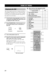
... Remote control buttons that the video input jack on your TV is connected to the VIDEO OUT jack of this unit to display the OSD.... 1 Check that display the OSD Page 1 Input selector buttons 37 2 TruBass 3 Beam mode buttons 4 Sound field program buttons 5 CH LEVEL 6 VOLUME +/- 7 MUTE 8 INPUTMODE 9 SLEEP 0 VOL MODE A SURROUND B MENU 54 40 49...STB TV INPUT2 TV MACRO YSP 5BEAM 1 INPUTMODE SLEEP ST+3BEAM 2 3BEAM 3 STEREO TARGET 4 5 6 MUSIC 7 MOVIE 8 VOL MODE 9 SPORTS 0 OFF +10 SURROUND TV CH LEVEL CINEMA DSP MENU TEST ENTER RETURN VOLUME CH TV VOL MUTE TV ...
... Remote control buttons that the video input jack on your TV is connected to the VIDEO OUT jack of this unit to display the OSD.... 1 Check that display the OSD Page 1 Input selector buttons 37 2 TruBass 3 Beam mode buttons 4 Sound field program buttons 5 CH LEVEL 6 VOLUME +/- 7 MUTE 8 INPUTMODE 9 SLEEP 0 VOL MODE A SURROUND B MENU 54 40 49...STB TV INPUT2 TV MACRO YSP 5BEAM 1 INPUTMODE SLEEP ST+3BEAM 2 3BEAM 3 STEREO TARGET 4 5 6 MUSIC 7 MOVIE 8 VOL MODE 9 SPORTS 0 OFF +10 SURROUND TV CH LEVEL CINEMA DSP MENU TEST ENTER RETURN VOLUME CH TV VOL MUTE TV ...

Owner's Manual
Page 31
... and the walls in your listening position. However, if this unit. - VOLUME CROSSOVER HIGH CUT MIN MAX MIN MAX Subwoofer 1 Connect the supplied optimizer microphone to the OPTIMIZER MIC jack on a conventional clockface and set the volume between the optimizer microphone and the walls...the optimizer microphone within 1 m from the center height of this unit. • Do not connect the optimizer microphone to an extension cable as doing so may result in an inaccurate sound optimization. • An error may want to use a tripod or the supplied cardboard microphone stand ...
... and the walls in your listening position. However, if this unit. - VOLUME CROSSOVER HIGH CUT MIN MAX MIN MAX Subwoofer 1 Connect the supplied optimizer microphone to the OPTIMIZER MIC jack on a conventional clockface and set the volume between the optimizer microphone and the walls...the optimizer microphone within 1 m from the center height of this unit. • Do not connect the optimizer microphone to an extension cable as doing so may result in an inaccurate sound optimization. • An error may want to use a tripod or the supplied cardboard microphone stand ...

Owner's Manual
Page 32
... TV AUX INPUT1 INPUT2 MACRO YSP ( ) INPUTMODE SLEEP 5BEAM 1 ST+3BEAM 2 3BEAM 3 STEREO UNIVERSAL 4 5 6 MUSIC 7 MOVIE 8 NIGHT 9 SPORTS 0 OFF +10 SURROUND CH LEVEL CINEMA DSP MENU 1 Disassemble the three parts of the cardboard microphone stand originally put together. Using AUTO SETUP Once the optimizer microphone is firmly connected to this unit and properly...
... TV AUX INPUT1 INPUT2 MACRO YSP ( ) INPUTMODE SLEEP 5BEAM 1 ST+3BEAM 2 3BEAM 3 STEREO UNIVERSAL 4 5 6 MUSIC 7 MOVIE 8 NIGHT 9 SPORTS 0 OFF +10 SURROUND CH LEVEL CINEMA DSP MENU 1 Disassemble the three parts of the cardboard microphone stand originally put together. Using AUTO SETUP Once the optimizer microphone is firmly connected to this unit and properly...

Owner's Manual
Page 35
The following points once again before starting the AUTO SETUP procedure. • Is the optimizer microphone firmly connected to start in 10 sec) are displayed in order as concrete walls. 7 Check the following screen appears on the shelf. REFLECTING (Reflecting) Use to select... or SOUND OPTIMZ only in step 5. SETTING VOLUME MEASURE DISTANCE MEASURE FREO CHAR MEASURE VOLUME Skipped if you selected BEAM OPTIMZ only in step 5. If you selected BEAM OPTIMZ only in 10 SEC Move aside or behind YSP *****----- SETUP ENTER WALL • Select WALL if the unit is mounted on the ...
The following points once again before starting the AUTO SETUP procedure. • Is the optimizer microphone firmly connected to start in 10 sec) are displayed in order as concrete walls. 7 Check the following screen appears on the shelf. REFLECTING (Reflecting) Use to select... or SOUND OPTIMZ only in step 5. SETTING VOLUME MEASURE DISTANCE MEASURE FREO CHAR MEASURE VOLUME Skipped if you selected BEAM OPTIMZ only in step 5. If you selected BEAM OPTIMZ only in 10 SEC Move aside or behind YSP *****----- SETUP ENTER WALL • Select WALL if the unit is mounted on the ...
Owner's Manual
Page 37
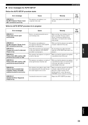
...other operations while the AUTO SETUP procedure is not connected to this unit and within 1 m from the center height of YSP. Make sure that the optimizer microphone is not placed...connected to this unit. Please re-try . ERROR E-5 Please check MIC position. MIC should be set in front of this unit. is installed in front of this unit. If the problem persists, contact the nearest YAMAHA... as possible. Make sure that the optimizer microphone 27 the sound produced by this unit and the sound output level is in the right distance from outside. The optimizer...
...other operations while the AUTO SETUP procedure is not connected to this unit and within 1 m from the center height of YSP. Make sure that the optimizer microphone is not placed...connected to this unit. Please re-try . ERROR E-5 Please check MIC position. MIC should be set in front of this unit. is installed in front of this unit. If the problem persists, contact the nearest YAMAHA... as possible. Make sure that the optimizer microphone 27 the sound produced by this unit and the sound output level is in the right distance from outside. The optimizer...