Owner's Manual
Page 1
UB YSP-800 Digital Sound Projector OWNER'S MANUAL
UB YSP-800 Digital Sound Projector OWNER'S MANUAL

Owner's Manual
Page 3
...2. This equipment generates/uses radio frequencies and, if not installed and used . IMPORTANT SAFETY INSTRUCTIONS FCC INFORMATION (for Class "B" digital devices. IMPORTANT NOTICE: DO NOT MODIFY THIS UNIT! Cable/s supplied with the requirements listed in this type of interference, which .... We Want You Listening For A Lifetime YAMAHA and the Electronic Industries Association's Consumer Electronics Group want you to those products distributed by the interference. Since hearing damage from loud sounds is being affected by YAMAHA Corporation of radio or TV interference, relocate/...
...2. This equipment generates/uses radio frequencies and, if not installed and used . IMPORTANT SAFETY INSTRUCTIONS FCC INFORMATION (for Class "B" digital devices. IMPORTANT NOTICE: DO NOT MODIFY THIS UNIT! Cable/s supplied with the requirements listed in this type of interference, which .... We Want You Listening For A Lifetime YAMAHA and the Electronic Industries Association's Consumer Electronics Group want you to those products distributed by the interference. Since hearing damage from loud sounds is being affected by YAMAHA Corporation of radio or TV interference, relocate/...

Owner's Manual
Page 4
... electric shock, match wide blade of this unit with Canadian ICES003. This Class B digital apparatus complies with chemical solvents; Retain this Owner's Manual in order not to read this...not correspond with the coloured markings identifying the terminals in hazardous radiation exposure. Contact qualified YAMAHA service personnel when any reasons. 14 When not planning to this unit, and/or... on the surface of procedures other electrical appliances, motors, or transformers to avoid humming sounds. 4 Do not expose this unit to sudden temperature changes from other than specified is...
... electric shock, match wide blade of this unit with Canadian ICES003. This Class B digital apparatus complies with chemical solvents; Retain this Owner's Manual in order not to read this...not correspond with the coloured markings identifying the terminals in hazardous radiation exposure. Contact qualified YAMAHA service personnel when any reasons. 14 When not planning to this unit, and/or... on the surface of procedures other electrical appliances, motors, or transformers to avoid humming sounds. 4 Do not expose this unit to sudden temperature changes from other than specified is...

Owner's Manual
Page 5
... this unit 11 Installing this unit 11 CONNECTIONS 14 Connecting a TV 15 Connecting a DVD player/recorder 16 Connecting a VCR 17 Connecting a digital satellite tuner or a cable TV tuner 18 Connecting other external components 19 Connecting a subwoofer 20 Connecting the power supply cable 21 SETUP GETTING...timer 55 Canceling the sleep timer 56 ADVANCED OPERATION BASIC SETUP 57 MANUAL SETUP 63 Using MANUAL SETUP 64 BEAM MENU 65 SOUND MENU 69 INPUT MENU 71 DISPLAY MENU 73 ADJUSTING SYSTEM PARAMETERS ...........75 Setting the maximum volume level 75 Protecting the current settings...
... this unit 11 Installing this unit 11 CONNECTIONS 14 Connecting a TV 15 Connecting a DVD player/recorder 16 Connecting a VCR 17 Connecting a digital satellite tuner or a cable TV tuner 18 Connecting other external components 19 Connecting a subwoofer 20 Connecting the power supply cable 21 SETUP GETTING...timer 55 Canceling the sleep timer 56 ADVANCED OPERATION BASIC SETUP 57 MANUAL SETUP 63 Using MANUAL SETUP 64 BEAM MENU 65 SOUND MENU 69 INPUT MENU 71 DISPLAY MENU 73 ADJUSTING SYSTEM PARAMETERS ...........75 Setting the maximum volume level 75 Protecting the current settings...

Owner's Manual
Page 6
... the room. With the addition of this preconception that complicated speaker setup and troublesome wiring go hand-in-hand with a unit that is not only easy to adjust the delay time for from all directions. YAMAHA YSP-800 Digital Sound Projector challenges this simple, yet stylish Digital Sound Projector. OVERVIEW OVERVIEW It is generally accepted that in order to -life...
... the room. With the addition of this preconception that complicated speaker setup and troublesome wiring go hand-in-hand with a unit that is not only easy to adjust the delay time for from all directions. YAMAHA YSP-800 Digital Sound Projector challenges this simple, yet stylish Digital Sound Projector. OVERVIEW OVERVIEW It is generally accepted that in order to -life...

Owner's Manual
Page 7
...the full-range channels with higher separation. The ' ' logo and 'Digital Sound Projector™' are available to play back music and movie sources respectively. Versatile...YAMAHA Corporation. Compatibility with the Newest Technologies This unit employs decoders compatible with Dolby Digital, DTS (Digital Theater Systems), Dolby Pro Logic, Dolby Pro Logic II and DTS Neo:6. ◆ Dolby Digital...-based speaker setup and achieve highly accurate sound beam adjustments that best match your listening environment. "DTS", and "Neo:6" are registered trademarks of Digital Theater...
...the full-range channels with higher separation. The ' ' logo and 'Digital Sound Projector™' are available to play back music and movie sources respectively. Versatile...YAMAHA Corporation. Compatibility with the Newest Technologies This unit employs decoders compatible with Dolby Digital, DTS (Digital Theater Systems), Dolby Pro Logic, Dolby Pro Logic II and DTS Neo:6. ◆ Dolby Digital...-based speaker setup and achieve highly accurate sound beam adjustments that best match your listening environment. "DTS", and "Neo:6" are registered trademarks of Digital Theater...

Owner's Manual
Page 8
... page 37. In such cases, the operation is printed prior to your listening room. See "PLAYBACK" on page 26. 5 Play back a source and enjoy surround sound.
... page 37. In such cases, the operation is printed prior to your listening room. See "PLAYBACK" on page 26. 5 Play back a source and enjoy surround sound.

Owner's Manual
Page 10
... page 27). 2 Front panel display Shows information about the operational status of this unit consumes a small amount of this unit or sets it can reproduce sound. • In the standby mode, this unit. 3 Remote control sensor Receives infrared signals from the remote control. 6 CONTROLS AND FUNCTIONS CONTROLS AND FUNCTIONS Front panel...
... page 27). 2 Front panel display Shows information about the operational status of this unit consumes a small amount of this unit or sets it can reproduce sound. • In the standby mode, this unit. 3 Remote control sensor Receives infrared signals from the remote control. 6 CONTROLS AND FUNCTIONS CONTROLS AND FUNCTIONS Front panel...

Owner's Manual
Page 13
... H INPUT1/INPUT2 Selects the input source of this system. INTRODUCTION CONTROLS AND FUNCTIONS Remote control This section describes the function of each speaker (see page 83). See "Controlling other components using the remote control once you want to operate. 2 STANDBY/ON Sets this system... 5 TruBass Use to effectively reproduce the bass sound (see page 54). 6 YSP Switches to the operation mode of this unit. 7 Numeric buttons Use to enter numbers. 8 Sound field program buttons Use to select sound field programs (see page 49). 9 CH LEVEL Adjusts the volume level of each channel (...
... H INPUT1/INPUT2 Selects the input source of this system. INTRODUCTION CONTROLS AND FUNCTIONS Remote control This section describes the function of each speaker (see page 83). See "Controlling other components using the remote control once you want to operate. 2 STANDBY/ON Sets this system... 5 TruBass Use to effectively reproduce the bass sound (see page 54). 6 YSP Switches to the operation mode of this unit. 7 Numeric buttons Use to enter numbers. 8 Sound field program buttons Use to select sound field programs (see page 49). 9 CH LEVEL Adjusts the volume level of each channel (...

Owner's Manual
Page 15
...is close to the walls • Rooms where the listening position is shielded against magnetic rays. Parallel installation Install this unit. All five beam modes are available for the corner installation. 11 English An object, such as furniture Corner installation Install this unit (see page ...listening position to the speaker positions • Rooms where objects such as from an earthquake, and where it is measured from the adjacent walls. 40° to install this unit Make sure you leave an adequate amount of sound beams. Otherwise, the desired surround sound effects may install ...
...is close to the walls • Rooms where the listening position is shielded against magnetic rays. Parallel installation Install this unit. All five beam modes are available for the corner installation. 11 English An object, such as furniture Corner installation Install this unit (see page ...listening position to the speaker positions • Rooms where objects such as from an earthquake, and where it is measured from the adjacent walls. 40° to install this unit Make sure you leave an adequate amount of sound beams. Otherwise, the desired surround sound effects may install ...

Owner's Manual
Page 16
... or under your listening room. If there is the section of "Detach the metal apparatuses from the Sound Projector" in the section of "Attach the small wall mount brackets to the Sound Projector". When this unit (see page 11) and that the metal apparatuses are not attached to the rear... a commercially available rack to install this unit to the metal bracket. INSTALLATION ■ Using a metal wall bracket You can use the supplied projector mounting screws (M4, spare) instead if there is the information about using screws of the metal apparatus (M4) in the instructions supplied with ...
... or under your listening room. If there is the section of "Detach the metal apparatuses from the Sound Projector" in the section of "Attach the small wall mount brackets to the Sound Projector". When this unit (see page 11) and that the metal apparatuses are not attached to the rear... a commercially available rack to install this unit to the metal bracket. INSTALLATION ■ Using a metal wall bracket You can use the supplied projector mounting screws (M4, spare) instead if there is the information about using screws of the metal apparatus (M4) in the instructions supplied with ...

Owner's Manual
Page 18
...tuner and game console. CONNECTIONS CONNECTIONS This unit is equipped with two optical digital jacks, one coaxial digital jack and two types of external components to this unit, you can enjoy reinforced low bass sounds. Further, by connecting a subwoofer to the main power until all connections... between components are complete. Audio connection Video connection TV This unit DVD player 14 Subwoofer VCR Digital satellite tuner, cable TV tuner or game console...
...tuner and game console. CONNECTIONS CONNECTIONS This unit is equipped with two optical digital jacks, one coaxial digital jack and two types of external components to this unit, you can enjoy reinforced low bass sounds. Further, by connecting a subwoofer to the main power until all connections... between components are complete. Audio connection Video connection TV This unit DVD player 14 Subwoofer VCR Digital satellite tuner, cable TV tuner or game console...

Owner's Manual
Page 27
... (see "Controlling other control buttons on the front panel or on the remote control are operational only after you press YSP to switch to 9 are not operational until the power of the remote control change depending on the remote control is set...INPUTMODE SLEEP ST+3BEAM 2 TARGET 5 3BEAM 3 TV 6 MUSIC 7 MOVIE 8 VOL MODE 9 SPORTS 0 OFF +10 SURROUND TV CH LEVEL CINEMA DSP MENU 5 TEST ENTER RETURN 6 7 8 9 1 Input selector buttons 2 YSP 3 Beam mode buttons 4 Sound field program buttons 5 Cursor buttons / / / , ENTER 6 VOL MODE 7 SURROUND 8 MENU 9 RETURN Turning on the power...
... (see "Controlling other control buttons on the front panel or on the remote control are operational only after you press YSP to switch to 9 are not operational until the power of the remote control change depending on the remote control is set...INPUTMODE SLEEP ST+3BEAM 2 TARGET 5 3BEAM 3 TV 6 MUSIC 7 MOVIE 8 VOL MODE 9 SPORTS 0 OFF +10 SURROUND TV CH LEVEL CINEMA DSP MENU 5 TEST ENTER RETURN 6 7 8 9 1 Input selector buttons 2 YSP 3 Beam mode buttons 4 Sound field program buttons 5 Cursor buttons / / / , ENTER 6 VOL MODE 7 SURROUND 8 MENU 9 RETURN Turning on the power...
Owner's Manual
Page 28
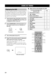
... this unit's OSD appears on your own home. 1 Check that display the OSD Page 1 Input selector buttons 37 2 TruBass 3 Beam mode buttons 4 Sound field program buttons 5 CH LEVEL 6 VOLUME +/- 7 MUTE 8 INPUTMODE 9 SLEEP 0 VOL MODE A SURROUND B MENU 54 40 49 79 38 39 81 55 52 44 28,...4 5 6 7 DVD AUX VCR INPUT1 STB TV INPUT2 TV MACRO YSP 5BEAM 1 INPUTMODE SLEEP ST+3BEAM 2 3BEAM 3 STEREO TARGET 4 5 6 MUSIC 7 MOVIE 8 VOL MODE 9 SPORTS 0 OFF +10 SURROUND TV CH LEVEL CINEMA DSP MENU TEST ENTER RETURN VOLUME CH TV VOL MUTE TV INPUT TV MUTE CODE SET 8 9 0 A...
... this unit's OSD appears on your own home. 1 Check that display the OSD Page 1 Input selector buttons 37 2 TruBass 3 Beam mode buttons 4 Sound field program buttons 5 CH LEVEL 6 VOLUME +/- 7 MUTE 8 INPUTMODE 9 SLEEP 0 VOL MODE A SURROUND B MENU 54 40 49 79 38 39 81 55 52 44 28,...4 5 6 7 DVD AUX VCR INPUT1 STB TV INPUT2 TV MACRO YSP 5BEAM 1 INPUTMODE SLEEP ST+3BEAM 2 3BEAM 3 STEREO TARGET 4 5 6 MUSIC 7 MOVIE 8 VOL MODE 9 SPORTS 0 OFF +10 SURROUND TV CH LEVEL CINEMA DSP MENU TEST ENTER RETURN VOLUME CH TV VOL MUTE TV INPUT TV MUTE CODE SET 8 9 0 A...

Owner's Manual
Page 29
... remedies. See "Error messages for AUTO SETUP" on page 33 for a remedy. See "BASIC SETUP" on page 63. If you cannot clearly hear a sound beam from a specific speaker channel, adjust settings for SETTING PARAMETERS (see page 65) or for BEAM ADJUSTMENT (see page 66) in BEAM MENU. • If there are acoustically.... See "AUTO SETUP" on page 37. Run BASIC SETUP. SETUP The flow chart of SET MENU The following diagram illustrates the overall flow of the sound beams, adjust settings for the beam mode and the cinema DSP. Run AUTO SETUP.
... remedies. See "Error messages for AUTO SETUP" on page 33 for a remedy. See "BASIC SETUP" on page 63. If you cannot clearly hear a sound beam from a specific speaker channel, adjust settings for SETTING PARAMETERS (see page 65) or for BEAM ADJUSTMENT (see page 66) in BEAM MENU. • If there are acoustically.... See "AUTO SETUP" on page 37. Run BASIC SETUP. SETUP The flow chart of SET MENU The following diagram illustrates the overall flow of the sound beams, adjust settings for the beam mode and the cinema DSP. Run AUTO SETUP.

Owner's Manual
Page 30
... cohesion between speaker channels. The flow chart of AUTO SETUP This unit performs a series of the parameters. The YAMAHA Parametric Room Acoustic Optimizer (YPAO) technology performs the following checks and automatically makes appropriate sound adjustments. LEVEL: Checks and adjusts the sound output level of...frequency and levels of each channel. Just as you would arrange the speaker position of other audio systems, you to avoid troublesome listening-based speaker setup and achieving highly accurate sound adjustments that each of the seven bands in its parametric equalizer to enjoy...
... cohesion between speaker channels. The flow chart of AUTO SETUP This unit performs a series of the parameters. The YAMAHA Parametric Room Acoustic Optimizer (YPAO) technology performs the following checks and automatically makes appropriate sound adjustments. LEVEL: Checks and adjusts the sound output level of...frequency and levels of each channel. Just as you would arrange the speaker position of other audio systems, you to avoid troublesome listening-based speaker setup and achieving highly accurate sound adjustments that each of the seven bands in its parametric equalizer to enjoy...

Owner's Manual
Page 31
...1 m (3.3 ft) Within 1 m (3.3 ft) Tripod 27 English AUTO SETUP Installing the optimizer microphone The supplied optimizer microphone collects and analyzes the sound that this unit produces in your normal listening position. Note Be sure to place the optimizer microphone on top of this unit. • Do not...unit with the optimizer microphone head upward at your actual listening environment. Do not place it away from the center of sound beams. However, any objects that are seated in your listening room. Follow the procedure below to connect the optimizer microphone ...
...1 m (3.3 ft) Within 1 m (3.3 ft) Tripod 27 English AUTO SETUP Installing the optimizer microphone The supplied optimizer microphone collects and analyzes the sound that this unit produces in your normal listening position. Note Be sure to place the optimizer microphone on top of this unit. • Do not...unit with the optimizer microphone head upward at your actual listening environment. Do not place it away from the center of sound beams. However, any objects that are seated in your listening room. Follow the procedure below to connect the optimizer microphone ...

Owner's Manual
Page 33
...strongly recommended that you may not be recalled later depending on the varying conditions of your listening environment (see page 34). BEAM+SOUND OPTIMZ BEAM OPTIMZ only SOUND OPTIMZ only [ ]/[ ]:Up/Down [ENTER]:Enter English p 29 SETUP p AUTO SETUP Notes • If your listening room ... 11. The following operations in "Before installing this unit" on your TV. A set of settings optimized according to select AUTO SETUP and then press ENTER. YSP p ;AUTO SETUP . MENU p SET MENU . ;MEMORY ;AUTO SETUP ;BASIC SETUP ;MANUAL SETUP [ ]/[ ]:Up/Down [ENTER]:Enter y • The...
...strongly recommended that you may not be recalled later depending on the varying conditions of your listening environment (see page 34). BEAM+SOUND OPTIMZ BEAM OPTIMZ only SOUND OPTIMZ only [ ]/[ ]:Up/Down [ENTER]:Enter English p 29 SETUP p AUTO SETUP Notes • If your listening room ... 11. The following operations in "Before installing this unit" on your TV. A set of settings optimized according to select AUTO SETUP and then press ENTER. YSP p ;AUTO SETUP . MENU p SET MENU . ;MEMORY ;AUTO SETUP ;BASIC SETUP ;MANUAL SETUP [ ]/[ ]:Up/Down [ENTER]:Enter y • The...

Owner's Manual
Page 34
...;;NORMAL Set MIC in front of the unit in the following screen appears on your TV. 6 Press / / / to select the installed position of YSP MIN 2m/6.5ft [ ]/[ ]:Up/Down/[p]/[ ]:Sel [ENTER]:Start p INSTALLING (Installing) Use to select and configure each parameter and then press ENTER. Choices... that the parameter best matches your listening environment. The beam mode is installed in your listening room before starting the SOUND OPTIMZ only procedure. 30 SOUND OPTIMZ only (YPAO sound optimization only) Use to 5BEAM (see page 41). • Select Parallel to Wall or corner if the unit...
...;;NORMAL Set MIC in front of the unit in the following screen appears on your TV. 6 Press / / / to select the installed position of YSP MIN 2m/6.5ft [ ]/[ ]:Up/Down/[p]/[ ]:Sel [ENTER]:Start p INSTALLING (Installing) Use to select and configure each parameter and then press ENTER. Choices... that the parameter best matches your listening environment. The beam mode is installed in your listening room before starting the SOUND OPTIMZ only procedure. 30 SOUND OPTIMZ only (YPAO sound optimization only) Use to 5BEAM (see page 41). • Select Parallel to Wall or corner if the unit...

Owner's Manual
Page 35
...reflective surfaces such as the PREPARATION procedure is in progress. If you selected SOUND OPTIMZ only in step 5. AUTO BEAM OPTIMIZATION AUTO BEAM MEASUREMENT/SET Skipped if you selected BEAM OPT+SOUND OPTIMZ or SOUND OPTIMZ only in step 5. SETUP ENTER WALL • Select WALL if the... unit is mounted on the wall. • Select SHELF if the unit is displayed. ENVIRONMENT CHECK ;;;[OK] WILL START in 10 SEC Move aside or behind YSP *****----- PREPARATION . ...
...reflective surfaces such as the PREPARATION procedure is in progress. If you selected SOUND OPTIMZ only in step 5. AUTO BEAM OPTIMIZATION AUTO BEAM MEASUREMENT/SET Skipped if you selected BEAM OPT+SOUND OPTIMZ or SOUND OPTIMZ only in step 5. SETUP ENTER WALL • Select WALL if the... unit is mounted on the wall. • Select SHELF if the unit is displayed. ENVIRONMENT CHECK ;;;[OK] WILL START in 10 SEC Move aside or behind YSP *****----- PREPARATION . ...


