
Owner's Manual
Page 5
...16 Connecting a DVD player/recorder 17 Connecting a VCR 18 Connecting a digital satellite tuner or a cable TV tuner 19 Connecting a digital airwave tuner 20 Connecting other external components 21 Connecting a subwoofer 22 Affixing...MENU 27 AUTO SETUP 28 The flow chart of AUTO SETUP 28 Installing the optimizer microphone 29 Using AUTO SETUP 31 USING THE SYSTEM MEMORY 36 Saving settings 36 Loading ...ADVANCED OPERATION BASIC SETUP 62 MANUAL SETUP 68 Using MANUAL SETUP 69 BEAM MENU 70 SOUND MENU 74 INPUT MENU 77 DISPLAY MENU 79 ADJUSTING SYSTEM PARAMETERS ...........80 Setting the...
...16 Connecting a DVD player/recorder 17 Connecting a VCR 18 Connecting a digital satellite tuner or a cable TV tuner 19 Connecting a digital airwave tuner 20 Connecting other external components 21 Connecting a subwoofer 22 Affixing...MENU 27 AUTO SETUP 28 The flow chart of AUTO SETUP 28 Installing the optimizer microphone 29 Using AUTO SETUP 31 USING THE SYSTEM MEMORY 36 Saving settings 36 Loading ...ADVANCED OPERATION BASIC SETUP 62 MANUAL SETUP 68 Using MANUAL SETUP 69 BEAM MENU 70 SOUND MENU 74 INPUT MENU 77 DISPLAY MENU 79 ADJUSTING SYSTEM PARAMETERS ...........80 Setting the...
Owner's Manual
Page 7
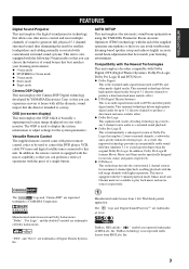
... FEATURES FEATURES Digital Sound Projector This unit employs the digital sound projector technology that allows one slim unit to control and steer multiple channels of sound to generate full, physical 5.1 channel surround sound, thus eliminating...Digital This unit employs the Cinema DSP Digital technology developed by YAMAHA Electronics Corp. so that you can perform a series of YAMAHA Corporation. AUTO SETUP This unit employs the automatic sound beam optimization using the YAMAHA Parametric Room Acoustic Optimizer (YPAO) technology with the aid of the supplied optimizer microphone...
... FEATURES FEATURES Digital Sound Projector This unit employs the digital sound projector technology that allows one slim unit to control and steer multiple channels of sound to generate full, physical 5.1 channel surround sound, thus eliminating...Digital This unit employs the Cinema DSP Digital technology developed by YAMAHA Electronics Corp. so that you can perform a series of YAMAHA Corporation. AUTO SETUP This unit employs the automatic sound beam optimization using the YAMAHA Parametric Room Acoustic Optimizer (YPAO) technology with the aid of the supplied optimizer microphone...

Owner's Manual
Page 9
... VCR INPUT1 STB TV INPUT2 TV MACRO YSP 5BEAM 1 INPUTMODE SLEEP ST+3BEAM 2 3BEAM 3 STEREO TARGET 4 5 6 MUSIC 7 MOVIE 8 VOL MODE 9 SPORTS 0 OFF +10 SURROUND CH LEVEL CINEMA DSP MENU TEST ENTER RETURN VOLUME CH TV VOL Video pin cable (×1) Digital audio pin cable (×1) (Yellow) Optimizer microphone (×1) (Orange) Audio pin cable (×1) MUTE...
... VCR INPUT1 STB TV INPUT2 TV MACRO YSP 5BEAM 1 INPUTMODE SLEEP ST+3BEAM 2 3BEAM 3 STEREO TARGET 4 5 6 MUSIC 7 MOVIE 8 VOL MODE 9 SPORTS 0 OFF +10 SURROUND CH LEVEL CINEMA DSP MENU TEST ENTER RETURN VOLUME CH TV VOL Video pin cable (×1) Digital audio pin cable (×1) (Yellow) Optimizer microphone (×1) (Orange) Audio pin cable (×1) MUTE...

Owner's Manual
Page 10
CONTROLS AND FUNCTIONS CONTROLS AND FUNCTIONS Front panel 1 23 INPUT VOLUME + STANDBY/ON 4 5 6 1 OPTIMIZER MIC jack Use to connect the supplied optimizer microphone to be a 4 to 5-second delay before it to switch between input sources (TV, STB, VCR, DVD or AUX). See page 39 for details...level of all audio channels (see page 28). 2 Front panel display Shows information about the operational status of this unit or sets it can reproduce sound. • In the standby mode, this unit. 3 Remote control sensor Receives infrared signals from the remote control. 6 Notes • When ...
CONTROLS AND FUNCTIONS CONTROLS AND FUNCTIONS Front panel 1 23 INPUT VOLUME + STANDBY/ON 4 5 6 1 OPTIMIZER MIC jack Use to connect the supplied optimizer microphone to be a 4 to 5-second delay before it to switch between input sources (TV, STB, VCR, DVD or AUX). See page 39 for details...level of all audio channels (see page 28). 2 Front panel display Shows information about the operational status of this unit or sets it can reproduce sound. • In the standby mode, this unit. 3 Remote control sensor Receives infrared signals from the remote control. 6 Notes • When ...
Owner's Manual
Page 32
...employs the beam optimization feature and the YAMAHA Parametric Room Acoustic Optimizer (YPAO) technology with the aid of the supplied optimizer microphone, allowing you need to set the beam angle to enjoy the best possible sound from this unit. EQUALIZING: Adjusts frequency ... room and broadening the cohesion between speaker channels. The YAMAHA Parametric Room Acoustic Optimizer (YPAO) technology performs the following checks and automatically makes appropriate sound adjustments. DISTANCE: Checks the phase and the distance of each sound beam reaches the listening position at the...
...employs the beam optimization feature and the YAMAHA Parametric Room Acoustic Optimizer (YPAO) technology with the aid of the supplied optimizer microphone, allowing you need to set the beam angle to enjoy the best possible sound from this unit. EQUALIZING: Adjusts frequency ... room and broadening the cohesion between speaker channels. The YAMAHA Parametric Room Acoustic Optimizer (YPAO) technology performs the following checks and automatically makes appropriate sound adjustments. DISTANCE: Checks the phase and the distance of each sound beam reaches the listening position at the...
Owner's Manual
Page 33
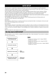
... upward at your normal listening position. SETUP AUTO SETUP Installing the optimizer microphone The supplied optimizer microphone collects and analyzes the sound that this unit. • Make sure that there are no large obstacles between the optimizer microphone and the walls in your listening room. Notes • After you have completed the AUTO SETUP...
... upward at your normal listening position. SETUP AUTO SETUP Installing the optimizer microphone The supplied optimizer microphone collects and analyzes the sound that this unit. • Make sure that there are no large obstacles between the optimizer microphone and the walls in your listening room. Notes • After you have completed the AUTO SETUP...

Owner's Manual
Page 34
... separate parts (one circular-shaped part and two longitudinal-shaped parts) of the cardboard microphone stand originally put together. 1 2 Optimizer microphone position More than 2 m Imaginary center line Within 1 m Within 1 m Cardboard microphone stand 3 4 1 Disassemble the three parts of the cardboard microphone stand originally put together. 2 Insert one of the longitudinal-shaped part into the crevice...
... separate parts (one circular-shaped part and two longitudinal-shaped parts) of the cardboard microphone stand originally put together. 1 2 Optimizer microphone position More than 2 m Imaginary center line Within 1 m Within 1 m Cardboard microphone stand 3 4 1 Disassemble the three parts of the cardboard microphone stand originally put together. 2 Insert one of the longitudinal-shaped part into the crevice...

Owner's Manual
Page 35
...unit is firmly connected to this unit so that you may not obstruct the path of sound beams. To achieve the best results possible, however, it is strongly recommended that you...procedure (see page 36). AUTO SETUP Using AUTO SETUP Once the optimizer microphone is installed in one of the rooms described in your listening room, follow the procedure ...TV DVD VCR STB TV AUX INPUT1 INPUT2 MACRO YSP ( ) INPUTMODE SLEEP 5BEAM 1 ST+3BEAM 2 3BEAM 3 STEREO UNIVERSAL 4 5 6 MUSIC 7 MOVIE 8 NIGHT 9 SPORTS 0 OFF +10 SURROUND CH LEVEL CINEMA DSP MENU Notes • If your ...
...unit is firmly connected to this unit so that you may not obstruct the path of sound beams. To achieve the best results possible, however, it is strongly recommended that you...procedure (see page 36). AUTO SETUP Using AUTO SETUP Once the optimizer microphone is installed in one of the rooms described in your listening room, follow the procedure ...TV DVD VCR STB TV AUX INPUT1 INPUT2 MACRO YSP ( ) INPUTMODE SLEEP 5BEAM 1 ST+3BEAM 2 3BEAM 3 STEREO UNIVERSAL 4 5 6 MUSIC 7 MOVIE 8 NIGHT 9 SPORTS 0 OFF +10 SURROUND CH LEVEL CINEMA DSP MENU Notes • If your ...

Owner's Manual
Page 37
... reflective surfaces such as concrete walls. 7 Check the following points once again before starting the AUTO SETUP procedure. • Is the optimizer microphone firmly connected to Wall if the unit is mounted on the shelf. Choices: NORMAL (Normal), HI ECHO (High echo) • Select ...to 5BEAM (see page 43). • Select Parallel to this unit? • Is the optimizer microphone placed in a proper location? • Are there any large obstacles in between the optimizer microphone and the walls in the corner. Choices: SHELF (Shelf mount), WALL (Wall mount) ENTER SHELF INSTALLING...
... reflective surfaces such as concrete walls. 7 Check the following points once again before starting the AUTO SETUP procedure. • Is the optimizer microphone firmly connected to Wall if the unit is mounted on the shelf. Choices: NORMAL (Normal), HI ECHO (High echo) • Select ...to 5BEAM (see page 43). • Select Parallel to this unit? • Is the optimizer microphone placed in a proper location? • Are there any large obstacles in between the optimizer microphone and the walls in the corner. Choices: SHELF (Shelf mount), WALL (Wall mount) ENTER SHELF INSTALLING...

Owner's Manual
Page 39
... problem persists, contact the nearest YAMAHA service center for AUTO SETUP AUTO SETUP Before the AUTO SETUP procedure starts Error message Cause ERROR E-2 No MIC Detected. The optimizer microphone is smaller than 2 m from... Please test in a proper location. The optimizer microphone cannot collect Make sure that the optimizer microphone 29 the sound produced by this unit and the sound output level is firmly connected to this unit. Please...There is in front of YSP. MIC should be set in progress. Make sure that your listening room. Please re-try.
... problem persists, contact the nearest YAMAHA service center for AUTO SETUP AUTO SETUP Before the AUTO SETUP procedure starts Error message Cause ERROR E-2 No MIC Detected. The optimizer microphone is smaller than 2 m from... Please test in a proper location. The optimizer microphone cannot collect Make sure that the optimizer microphone 29 the sound produced by this unit and the sound output level is firmly connected to this unit. Please...There is in front of YSP. MIC should be set in progress. Make sure that your listening room. Please re-try.

Owner's Manual
Page 100
...16 to 19 AUTO SETUP 28 B BASIC SETUP 62 Beam modes 42 C Cable clamp 23 Cardboard microphone stand 30 Coaxial digital output jack 8 Coaxial digital input jack 8 D Digital audio pin cable 17 Display 7, 26 Dolby Digital 46 Dolby Pro Logic 46 Dolby Pro Logic II 46 DTS 46 DTS Neo:6 46 Dynamic range... 7 L On-screen display (OSD 26 Optical cable 16, 19, 21 Optimizer microphone 29 P PCM 86 Power supply cable 23 R Remote control 9, 24 Remote control code 87 S Surround mode 46 Sleep timer 60 SET MENU 26 Sound field program 51 T Test tone 83 TruBass 58 TV macro 90 V Video pin...
...16 to 19 AUTO SETUP 28 B BASIC SETUP 62 Beam modes 42 C Cable clamp 23 Cardboard microphone stand 30 Coaxial digital output jack 8 Coaxial digital input jack 8 D Digital audio pin cable 17 Display 7, 26 Dolby Digital 46 Dolby Pro Logic 46 Dolby Pro Logic II 46 DTS 46 DTS Neo:6 46 Dynamic range... 7 L On-screen display (OSD 26 Optical cable 16, 19, 21 Optimizer microphone 29 P PCM 86 Power supply cable 23 R Remote control 9, 24 Remote control code 87 S Surround mode 46 Sleep timer 60 SET MENU 26 Sound field program 51 T Test tone 83 TruBass 58 TV macro 90 V Video pin...

Owner's Manual
Page 101
...(Optical 2 (Digital) AUDIO DVD (Coaxial 1 (Digital) COMPOSITE VIDEO, VCR, DVD/AUX, STB 3 COMPONENT VIDEO, DVD/AUX, STB 2 pairs • Output Jacks SUBWOOFER (1.5 V, less than 120 Hz 1 (Subwoofer) VIDEO (1 Vp-p, 75 1 (Composite) COMPONENT VIDEO (Y: 1 Vp-p, 75 Ω PB/PR: 0.5 Vp-p, 75 1 • System Connector Jacks OPTIMIZER MIC 1 (Microphone input) RS-... SECTION • Maximum Output Power (EIAJ 2 W (1 kHz, 10% THD, 4 Ω) × 40 20 W (100 Hz, 10% THD, 3 Ω) × 2 SPEAKER SECTION Small dia. and Canada models AC 120 V, 60 Hz [Australia model AC 240 V, 50 Hz [U.K.
...(Optical 2 (Digital) AUDIO DVD (Coaxial 1 (Digital) COMPOSITE VIDEO, VCR, DVD/AUX, STB 3 COMPONENT VIDEO, DVD/AUX, STB 2 pairs • Output Jacks SUBWOOFER (1.5 V, less than 120 Hz 1 (Subwoofer) VIDEO (1 Vp-p, 75 1 (Composite) COMPONENT VIDEO (Y: 1 Vp-p, 75 Ω PB/PR: 0.5 Vp-p, 75 1 • System Connector Jacks OPTIMIZER MIC 1 (Microphone input) RS-... SECTION • Maximum Output Power (EIAJ 2 W (1 kHz, 10% THD, 4 Ω) × 40 20 W (100 Hz, 10% THD, 3 Ω) × 2 SPEAKER SECTION Small dia. and Canada models AC 120 V, 60 Hz [Australia model AC 240 V, 50 Hz [U.K.

Owner's Manual
Page 105
...YSP-1000 QUICK REFERENCE GUIDE This quick reference guide explains steps to connect a TV and a DVD player to this unit and achieve the surround sound effects in Malaysia WG29110 Optimizer microphone position More than 2 m Imaginary center line Within 1 m Within 1 m Tripod Optimizer microphone... to the speaker positions • Rooms where objects such as furniture are likely to obstruct the path of sound beams •...unit Connect this unit to external components such as your TV, DVD player, VCR, digital satellite tuner, cable TV tuner, game console and a subwoofer. ■ Connecting ...
...YSP-1000 QUICK REFERENCE GUIDE This quick reference guide explains steps to connect a TV and a DVD player to this unit and achieve the surround sound effects in Malaysia WG29110 Optimizer microphone position More than 2 m Imaginary center line Within 1 m Within 1 m Tripod Optimizer microphone... to the speaker positions • Rooms where objects such as furniture are likely to obstruct the path of sound beams •...unit Connect this unit to external components such as your TV, DVD player, VCR, digital satellite tuner, cable TV tuner, game console and a subwoofer. ■ Connecting ...