
Owner's Manual
Page 1
UB YSP-1000 Digital Sound Projector OWNER'S MANUAL
UB YSP-1000 Digital Sound Projector OWNER'S MANUAL

Owner's Manual
Page 2
The exclamation point within an equilateral triangle is damaged, liquid has been spilled or objects have fallen into your safety. The wide blade or the third prong are provided for long periods of time. 14 Refer all instructions. 5 Do not use this apparatus during lightning storms or when unused for your outlet, consult an electrician for replacement of the obsolete outlet. 10 Protect the power supply cable from being walked on or pinched particularly at plugs, convenience receptacles, and the point where they exit from the apparatus. 11 Only use caution when moving the cart/apparatus...
The exclamation point within an equilateral triangle is damaged, liquid has been spilled or objects have fallen into your safety. The wide blade or the third prong are provided for long periods of time. 14 Refer all instructions. 5 Do not use this apparatus during lightning storms or when unused for your outlet, consult an electrician for replacement of the obsolete outlet. 10 Protect the power supply cable from being walked on or pinched particularly at plugs, convenience receptacles, and the point where they exit from the apparatus. 11 Only use caution when moving the cart/apparatus...
Owner's Manual
Page 3
... volume levels. IMPORTANT NOTICE: DO NOT MODIFY THIS UNIT! Modifications not expressly approved by YAMAHA may cause interference harmful to get the most importantly, without annoying blaring or distortion -... Part 15 for US customers) 1. IMPORTANT SAFETY INSTRUCTIONS FCC INFORMATION (for Class "B" digital devices. IMPORTANT: When connecting this product to accessories and/or another product use of this... not guarantee that lets the sound come through loud and clear without affecting your FCC authorization to avoid prolonged exposure from loud sounds is often undetectable until it at...
... volume levels. IMPORTANT NOTICE: DO NOT MODIFY THIS UNIT! Modifications not expressly approved by YAMAHA may cause interference harmful to get the most importantly, without annoying blaring or distortion -... Part 15 for US customers) 1. IMPORTANT SAFETY INSTRUCTIONS FCC INFORMATION (for Class "B" digital devices. IMPORTANT: When connecting this product to accessories and/or another product use of this... not guarantee that lets the sound come through loud and clear without affecting your FCC authorization to avoid prolonged exposure from loud sounds is often undetectable until it at...
Owner's Manual
Page 4
...this unit, and/or personal injury. this unit may overheat, possibly causing damage. 9 Do not use this unit - This Class B digital apparatus complies with the same or equivalent type. Note that the plug severed from the mains lead must be destroyed, as they may fall...of space above (or below) this unit for future reference. 2 Install this sound system in a well ventilated, cool, dry, clean place with liquid in a safe place for long periods of this unit. - YAMAHA will form when the surrounding temperature changes suddenly. IMPORTANT Please record the serial ...
...this unit, and/or personal injury. this unit may overheat, possibly causing damage. 9 Do not use this unit - This Class B digital apparatus complies with the same or equivalent type. Note that the plug severed from the mains lead must be destroyed, as they may fall...of space above (or below) this unit for future reference. 2 Install this sound system in a well ventilated, cool, dry, clean place with liquid in a safe place for long periods of this unit. - YAMAHA will form when the surrounding temperature changes suddenly. IMPORTANT Please record the serial ...

Owner's Manual
Page 5
... unit 11 CONNECTIONS 15 Connecting a TV 16 Connecting a DVD player/recorder 17 Connecting a VCR 18 Connecting a digital satellite tuner or a cable TV tuner 19 Connecting a digital airwave tuner 20 Connecting other external components 21 Connecting a subwoofer 22 Affixing the optical cable 23 Connecting the power...timer 60 Canceling the sleep timer 61 ADVANCED OPERATION BASIC SETUP 62 MANUAL SETUP 68 Using MANUAL SETUP 69 BEAM MENU 70 SOUND MENU 74 INPUT MENU 77 DISPLAY MENU 79 ADJUSTING SYSTEM PARAMETERS ...........80 Setting the maximum volume level 80 Protecting the current...
... unit 11 CONNECTIONS 15 Connecting a TV 16 Connecting a DVD player/recorder 17 Connecting a VCR 18 Connecting a digital satellite tuner or a cable TV tuner 19 Connecting a digital airwave tuner 20 Connecting other external components 21 Connecting a subwoofer 22 Affixing the optical cable 23 Connecting the power...timer 60 Canceling the sleep timer 61 ADVANCED OPERATION BASIC SETUP 62 MANUAL SETUP 68 Using MANUAL SETUP 69 BEAM MENU 70 SOUND MENU 74 INPUT MENU 77 DISPLAY MENU 79 ADJUSTING SYSTEM PARAMETERS ...........80 Setting the maximum volume level 80 Protecting the current...
Owner's Manual
Page 6
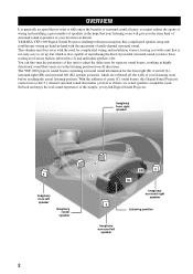
... go hand-in subwoofers (2) and individual speakers (40). YAMAHA YSP-1000 Digital Sound Projector challenges this simple, yet stylish Digital Sound Projector. Sit back and enjoy the real sound experience of your local movie theater. Imaginary front right speaker Imaginary front left speaker Imaginary center speaker C L R SR SL Imaginary surround right speaker Listening position Imaginary surround left (SL) speaker positions, which is also capable of reproducing...
... go hand-in subwoofers (2) and individual speakers (40). YAMAHA YSP-1000 Digital Sound Projector challenges this simple, yet stylish Digital Sound Projector. Sit back and enjoy the real sound experience of your local movie theater. Imaginary front right speaker Imaginary front left speaker Imaginary center speaker C L R SR SL Imaginary surround right speaker Listening position Imaginary surround left (SL) speaker positions, which is also capable of reproducing...
Owner's Manual
Page 7
... so that you can avoid troublesome listening-based speaker setup and achieve highly accurate sound beam adjustments that best match your listening environment. This surround technology deliver high-quality digital audio for . Manufactured under license from Dolby ... the need for satellite loudspeakers and cabling normally associated with conventional surround sound systems. This unit is also equipped with higher separation. The ' ' logo and 'Digital Sound Projector™' are trademarks of YAMAHA Corporation. TruBass, SRS and the " " symbol are registered trademarks ...
... so that you can avoid troublesome listening-based speaker setup and achieve highly accurate sound beam adjustments that best match your listening environment. This surround technology deliver high-quality digital audio for . Manufactured under license from Dolby ... the need for satellite loudspeakers and cabling normally associated with conventional surround sound systems. This unit is also equipped with higher separation. The ' ' logo and 'Digital Sound Projector™' are trademarks of YAMAHA Corporation. TruBass, SRS and the " " symbol are registered trademarks ...
Owner's Manual
Page 8
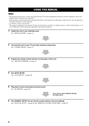
... SETUP" on page 68 and "REMOTE CONTROL FEATURES" on page 24. 4 Run AUTO SETUP. See "PLAYBACK" on page 28. 5 Play back a source and enjoy surround sound. See "AUTO SETUP" on page 39. See "CONNECTIONS" on page 15. 3 Prepare the remote control and turn on the power of improvements, etc. USING THIS...
... SETUP" on page 68 and "REMOTE CONTROL FEATURES" on page 24. 4 Run AUTO SETUP. See "PLAYBACK" on page 28. 5 Play back a source and enjoy surround sound. See "AUTO SETUP" on page 39. See "CONNECTIONS" on page 15. 3 Prepare the remote control and turn on the power of improvements, etc. USING THIS...

Owner's Manual
Page 9
... TV DVD AUX VCR INPUT1 STB TV INPUT2 TV MACRO YSP 5BEAM 1 INPUTMODE SLEEP ST+3BEAM 2 3BEAM 3 STEREO TARGET 4 5 6 MUSIC 7 MOVIE 8 VOL MODE 9 SPORTS 0 OFF +10 SURROUND CH LEVEL CINEMA DSP MENU TEST ENTER RETURN VOLUME CH TV VOL Video pin cable (×1) Digital audio pin cable (×1) (Yellow) Optimizer microphone (×1) (Orange) Audio...
... TV DVD AUX VCR INPUT1 STB TV INPUT2 TV MACRO YSP 5BEAM 1 INPUTMODE SLEEP ST+3BEAM 2 3BEAM 3 STEREO TARGET 4 5 6 MUSIC 7 MOVIE 8 VOL MODE 9 SPORTS 0 OFF +10 SURROUND CH LEVEL CINEMA DSP MENU TEST ENTER RETURN VOLUME CH TV VOL Video pin cable (×1) Digital audio pin cable (×1) (Yellow) Optimizer microphone (×1) (Orange) Audio...

Owner's Manual
Page 10
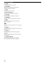
... (see page 40). 6 STANDBY/ON Turns on the power of this unit, you turn on the power of this unit or sets it can reproduce sound. • In the standby mode, this unit consumes a small amount of power in order to switch between input sources (TV, STB, VCR, DVD or AUX...
... (see page 40). 6 STANDBY/ON Turns on the power of this unit, you turn on the power of this unit or sets it can reproduce sound. • In the standby mode, this unit consumes a small amount of power in order to switch between input sources (TV, STB, VCR, DVD or AUX...

Owner's Manual
Page 11
INTRODUCTION Front panel display 12 3 CONTROLS AND FUNCTIONS 4 NIGHT SLEEP PCM DIGITAL PL VOL m ft mS dB 5 1 NIGHT indicator Lights up when the corresponding decoder of this unit. y You can adjust the brightness of the front panel ...
INTRODUCTION Front panel display 12 3 CONTROLS AND FUNCTIONS 4 NIGHT SLEEP PCM DIGITAL PL VOL m ft mS dB 5 1 NIGHT indicator Lights up when the corresponding decoder of this unit. y You can adjust the brightness of the front panel ...
Owner's Manual
Page 12
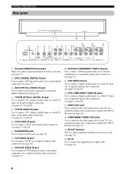
...B D 1 2 34 5 6 7 89 A C COMPONENT COMPONENT COMPONENT DVD COAXIAL AUX TV/STB OPTICAL TV/STB VCR VCR DVD/AUX STB RS-232C REMOTE IN DIGITAL IN AUDIO IN SUBWOOFER VIDEO IN VIDEO OUT 1 RS-232C/REMOTE IN terminals These are control expansion terminals for factory use only (see page 23...player/recorder or an external component via a composite analog video connection (see page 17). 0 DVD/AUX COMPONENT VIDEO IN jacks Use to connect a digital satellite tuner or a cable TV tuner via a component analog video connection (see pages 19 and 20). B STB COMPONENT VIDEO IN jacks Use to...
...B D 1 2 34 5 6 7 89 A C COMPONENT COMPONENT COMPONENT DVD COAXIAL AUX TV/STB OPTICAL TV/STB VCR VCR DVD/AUX STB RS-232C REMOTE IN DIGITAL IN AUDIO IN SUBWOOFER VIDEO IN VIDEO OUT 1 RS-232C/REMOTE IN terminals These are control expansion terminals for factory use only (see page 23...player/recorder or an external component via a composite analog video connection (see page 17). 0 DVD/AUX COMPONENT VIDEO IN jacks Use to connect a digital satellite tuner or a cable TV tuner via a component analog video connection (see pages 19 and 20). B STB COMPONENT VIDEO IN jacks Use to...

Owner's Manual
Page 13
...volume level (see page 41). Increases or decreases the volume level of this system. C MUTE Mutes the sound. See "Controlling other components using the remote control once you want to operate. 2 STANDBY/ON Sets this ... effectively reproduce the bass sound (see page 58). 6 YSP Switches to the operation mode of this unit. 7 Numeric buttons Use to enter numbers. 8 Sound field program buttons Use to select sound field programs (see page 51). 9 CH LEVEL Adjusts the volume ... CONTROLS AND FUNCTIONS Remote control This section describes the function of each speaker (see page 83).
...volume level (see page 41). Increases or decreases the volume level of this system. C MUTE Mutes the sound. See "Controlling other components using the remote control once you want to operate. 2 STANDBY/ON Sets this ... effectively reproduce the bass sound (see page 58). 6 YSP Switches to the operation mode of this unit. 7 Numeric buttons Use to enter numbers. 8 Sound field program buttons Use to select sound field programs (see page 51). 9 CH LEVEL Adjusts the volume ... CONTROLS AND FUNCTIONS Remote control This section describes the function of each speaker (see page 83).
Owner's Manual
Page 14
... the input source. See page 39 for playback (see page 88). O MENU Displays the setup menu on or off the volume modes (see page 60). R CH +/- J INPUTMODE Switches between channels of the TV or the VCR (see page 88). K SLEEP Sets the sleep timer (see page 56). M VOL MODE Turns on...
... the input source. See page 39 for playback (see page 88). O MENU Displays the setup menu on or off the volume modes (see page 60). R CH +/- J INPUTMODE Switches between channels of the TV or the VCR (see page 88). K SLEEP Sets the sleep timer (see page 56). M VOL MODE Turns on...

Owner's Manual
Page 15
... furniture obstructing the path of the wall when it is not in parallel with less than 2 m from the listening position to the speaker positions • Rooms where objects such as furniture y The availability of the beam mode depends on your TV screen becomes blurred or... this unit may install this unit in front of this unit Make sure you leave an adequate amount of your TV. All five beam modes are available for reflecting sound beams • Rooms with acoustically absorbent surfaces • Rooms with measurements outside the following range W (3 to 7 m) x H (2 to 3.5 m) x D (3 to...
... furniture obstructing the path of the wall when it is not in parallel with less than 2 m from the listening position to the speaker positions • Rooms where objects such as furniture y The availability of the beam mode depends on your TV screen becomes blurred or... this unit may install this unit in front of this unit Make sure you leave an adequate amount of your TV. All five beam modes are available for reflecting sound beams • Rooms with acoustically absorbent surfaces • Rooms with measurements outside the following range W (3 to 7 m) x H (2 to 3.5 m) x D (3 to...

Owner's Manual
Page 16
Example 3 Install this unit as close to the exact front of the wall as close to the exact center of your normal listening position. 12 Example 2 Install this unit so that the sound beams can be reflected off the walls. INSTALLATION ■ Installation examples Example 1 Install this unit as possible.
Example 3 Install this unit as close to the exact front of the wall as close to the exact center of your normal listening position. 12 Example 2 Install this unit so that the sound beams can be reflected off the walls. INSTALLATION ■ Installation examples Example 1 Install this unit as possible.

Owner's Manual
Page 17
Metal wall bracket INSTALLATION ■ Using a TV stand You can mount your TV on the stand placed on a commercially available rack to install this unit under your listening room. Stand TV This unit ■ Using a rack You can install this unit either above your TV. 13 For detailed information on installing this unit and the TV on the wall in a commercially available rack. TV This unit TV y Refer to the instructions supplied with the metal bracket for details on how to install the stand or how to mount this unit using a TV stand, refer to the installation manual ...
Metal wall bracket INSTALLATION ■ Using a TV stand You can mount your TV on the stand placed on a commercially available rack to install this unit under your listening room. Stand TV This unit ■ Using a rack You can install this unit either above your TV. 13 For detailed information on installing this unit and the TV on the wall in a commercially available rack. TV This unit TV y Refer to the instructions supplied with the metal bracket for details on how to install the stand or how to mount this unit using a TV stand, refer to the installation manual ...
Owner's Manual
Page 18
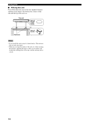
before securing the fasteners. Applying the tape to the bottom four corners of this unit and the top of the rack, etc. This unit may fall over and cause injury. • Make sure you wipe the surface of the rack, etc. INSTALLATION ■ Affixing this unit Peel off the film 2 1 Notes • Do not install this unit on top of a slanted surface. This unit Peel off the pad on the bottom Fasteners Peel off the film from each of the four supplied fasteners and then secure them to a dirty or wet surface will weaken the sticking power of the tape, and this unit may fall as a ...
before securing the fasteners. Applying the tape to the bottom four corners of this unit and the top of the rack, etc. This unit may fall over and cause injury. • Make sure you wipe the surface of the rack, etc. INSTALLATION ■ Affixing this unit Peel off the film 2 1 Notes • Do not install this unit on top of a slanted surface. This unit Peel off the pad on the bottom Fasteners Peel off the film from each of the four supplied fasteners and then secure them to a dirty or wet surface will weaken the sticking power of the tape, and this unit may fall as a ...
Owner's Manual
Page 19
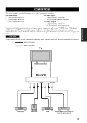
...CONNECTIONS CONNECTIONS This unit is equipped with the following types of audio/video input/output jacks: For audio input • 2 optical digital input jacks • 1 coaxial digital input jack • 2 sets of analog input jacks For video input • 3 composite analog input jacks • 2 sets... connection Video connection TV This unit DVD player Subwoofer VCR Digital satellite tuner, cable TV tuner or game console 15 CAUTION Do not connect this unit, see pages 16 to this unit, you can enjoy reinforced low bass sounds. Further, by connecting a subwoofer to 22.
...CONNECTIONS CONNECTIONS This unit is equipped with the following types of audio/video input/output jacks: For audio input • 2 optical digital input jacks • 1 coaxial digital input jack • 2 sets of analog input jacks For video input • 3 composite analog input jacks • 2 sets... connection Video connection TV This unit DVD player Subwoofer VCR Digital satellite tuner, cable TV tuner or game console 15 CAUTION Do not connect this unit, see pages 16 to this unit, you can enjoy reinforced low bass sounds. Further, by connecting a subwoofer to 22.
Owner's Manual
Page 20
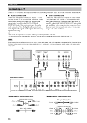
... video input jacks of output jack of your TV to the TV/STB OPTICAL your TV to the COMPONENT VIDEO OUT jacks of this DIGITAL IN jack of this unit COMPONENT COMPONENT COMPONENT DVD COAXIAL AUX TV/STB OPTICAL TV/STB VCR VCR DVD/AUX STB RS-232C REMOTE ... (supplied) (White) (Red) Optical cable (supplied) (Red) 16 Cables used for easy viewing when you connect this unit to the analog audio and optical digital audio output jacks at the analog audio output jacks. Note If you adjust the system parameters in the supplied cable clamp (see page 23). CONNECTIONS...
... video input jacks of output jack of your TV to the TV/STB OPTICAL your TV to the COMPONENT VIDEO OUT jacks of this DIGITAL IN jack of this unit COMPONENT COMPONENT COMPONENT DVD COAXIAL AUX TV/STB OPTICAL TV/STB VCR VCR DVD/AUX STB RS-232C REMOTE ... (supplied) (White) (Red) Optical cable (supplied) (Red) 16 Cables used for easy viewing when you connect this unit to the analog audio and optical digital audio output jacks at the analog audio output jacks. Note If you adjust the system parameters in the supplied cable clamp (see page 23). CONNECTIONS...
