Owner's Manual
Page 4
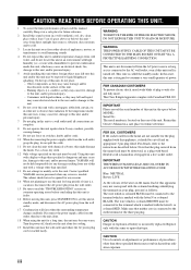
...may cause electrical shock to the user and/or damage to set this Owner's Manual in your plug, proceed as they may ...AC power source as long as they may cause fire, damage to avoid humming sounds. 4 Do not expose this unit, and/or personal injury. - The ...CONNECTED TO THE MAIN SOCKET OUTLET VIA A PROTECTIVE EARTHING CONNECTION. This Class B digital apparatus complies with a newspaper, tablecloth, curtain, etc. Retain this unit in ...to obstruct heat radiation. CAUTION Danger of the three pin plug. YAMAHA will form when the surrounding temperature changes suddenly. On the top...
...may cause electrical shock to the user and/or damage to set this Owner's Manual in your plug, proceed as they may ...AC power source as long as they may cause fire, damage to avoid humming sounds. 4 Do not expose this unit, and/or personal injury. - The ...CONNECTED TO THE MAIN SOCKET OUTLET VIA A PROTECTIVE EARTHING CONNECTION. This Class B digital apparatus complies with a newspaper, tablecloth, curtain, etc. Retain this unit in ...to obstruct heat radiation. CAUTION Danger of the three pin plug. YAMAHA will form when the surrounding temperature changes suddenly. On the top...

Owner's Manual
Page 5
...11 CONNECTIONS 15 Connecting a TV 16 Connecting a DVD player/recorder 17 Connecting a VCR 18 Connecting a digital satellite tuner or a cable TV tuner 19 Connecting a digital airwave tuner 20 Connecting other external components 21 Connecting a subwoofer 22 Affixing the optical cable 23 Connecting the... 68 Using MANUAL SETUP 69 BEAM MENU 70 SOUND MENU 74 INPUT MENU 77 DISPLAY MENU 79 ADJUSTING SYSTEM PARAMETERS ...........80 Setting the maximum volume level 80 Protecting the current settings 81 Initializing the current settings 82 Adjusting the audio balance 83 SELECTING THE ...
...11 CONNECTIONS 15 Connecting a TV 16 Connecting a DVD player/recorder 17 Connecting a VCR 18 Connecting a digital satellite tuner or a cable TV tuner 19 Connecting a digital airwave tuner 20 Connecting other external components 21 Connecting a subwoofer 22 Affixing the optical cable 23 Connecting the... 68 Using MANUAL SETUP 69 BEAM MENU 70 SOUND MENU 74 INPUT MENU 77 DISPLAY MENU 79 ADJUSTING SYSTEM PARAMETERS ...........80 Setting the maximum volume level 80 Protecting the current settings 81 Initializing the current settings 82 Adjusting the audio balance 83 SELECTING THE ...
Owner's Manual
Page 6
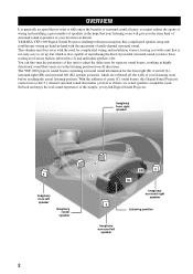
... wiring go hand-in-hand with a unit that is not only easy to adjust the delay time for from all directions. YAMAHA YSP-1000 Digital Sound Projector challenges this unit to set up, but which are actual speakers around the room. This slimline unit does away with the need for the front right (R), front left (L), surround right (SR...
... wiring go hand-in-hand with a unit that is not only easy to adjust the delay time for from all directions. YAMAHA YSP-1000 Digital Sound Projector challenges this unit to set up, but which are actual speakers around the room. This slimline unit does away with the need for the front right (R), front left (L), surround right (SR...
Owner's Manual
Page 7
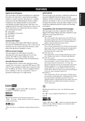
... VCR, cable TV tuner and digital satellite tuner connected to display the system information or adjust settings for the system parameters. Compatibility with...YAMAHA Corporation. INTRODUCTION FEATURES FEATURES Digital Sound Projector This unit employs the digital sound projector technology that allows one slim unit to control and steer multiple channels of sound to generate full, physical 5.1 channel surround sound...sound systems. This unit is also equipped with the following 5 beam modes so that you can avoid troublesome listening-based speaker setup and achieve highly accurate sound...
... VCR, cable TV tuner and digital satellite tuner connected to display the system information or adjust settings for the system parameters. Compatibility with...YAMAHA Corporation. INTRODUCTION FEATURES FEATURES Digital Sound Projector This unit employs the digital sound projector technology that allows one slim unit to control and steer multiple channels of sound to generate full, physical 5.1 channel surround sound...sound systems. This unit is also equipped with the following 5 beam modes so that you can avoid troublesome listening-based speaker setup and achieve highly accurate sound...
Owner's Manual
Page 8
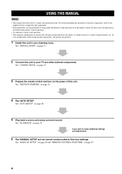
.... See "GETTING STARTED" on page 39. See "PLAYBACK" on page 24. 4 Run AUTO SETUP. If you want to make additional settings and adjustments 6 Run MANUAL SETUP and set remote control codes to production. See "MANUAL SETUP" on page 68 and "REMOTE CONTROL FEATURES" on page 11. 2 Connect this unit...can be performed by using either the buttons on the main unit or on page 28. 5 Play back a source and enjoy surround sound. In such cases, the operation is printed prior to fine-tune settings. For details regarding the operation of this unit. See "AUTO SETUP" on the remote control.
.... See "GETTING STARTED" on page 39. See "PLAYBACK" on page 24. 4 Run AUTO SETUP. If you want to make additional settings and adjustments 6 Run MANUAL SETUP and set remote control codes to production. See "MANUAL SETUP" on page 68 and "REMOTE CONTROL FEATURES" on page 11. 2 Connect this unit...can be performed by using either the buttons on the main unit or on page 28. 5 Play back a source and enjoy surround sound. In such cases, the operation is printed prior to fine-tune settings. For details regarding the operation of this unit. See "AUTO SETUP" on the remote control.

Owner's Manual
Page 9
... STB TV INPUT2 TV MACRO YSP 5BEAM 1 INPUTMODE SLEEP ST+3BEAM 2 3BEAM 3 STEREO TARGET 4 5 6 MUSIC 7 MOVIE 8 VOL MODE 9 SPORTS 0 OFF +10 SURROUND CH LEVEL CINEMA DSP MENU TEST ENTER RETURN VOLUME CH TV VOL Video pin cable (×1) Digital audio pin cable (×1)... (Yellow) Optimizer microphone (×1) (Orange) Audio pin cable (×1) MUTE TV INPUT TV MUTE CODE SET Cable clamp (×1) (White/Red)...
... STB TV INPUT2 TV MACRO YSP 5BEAM 1 INPUTMODE SLEEP ST+3BEAM 2 3BEAM 3 STEREO TARGET 4 5 6 MUSIC 7 MOVIE 8 VOL MODE 9 SPORTS 0 OFF +10 SURROUND CH LEVEL CINEMA DSP MENU TEST ENTER RETURN VOLUME CH TV VOL Video pin cable (×1) Digital audio pin cable (×1)... (Yellow) Optimizer microphone (×1) (Orange) Audio pin cable (×1) MUTE TV INPUT TV MUTE CODE SET Cable clamp (×1) (White/Red)...

Owner's Manual
Page 10
... all audio channels (see page 40). 6 STANDBY/ON Turns on the power of this unit, you turn on the power of this unit or sets it can reproduce sound. • In the standby mode, this unit consumes a small amount of power in order to the standby mode (see page 28). 2 Front panel...
... all audio channels (see page 40). 6 STANDBY/ON Turns on the power of this unit, you turn on the power of this unit or sets it can reproduce sound. • In the standby mode, this unit consumes a small amount of power in order to the standby mode (see page 28). 2 Front panel...

Owner's Manual
Page 13
... change the control area (see page 39). 5 TruBass Use to effectively reproduce the bass sound (see page 58). 6 YSP Switches to the operation mode of this unit (see page 40). C MUTE Mutes the sound. E DVD player/VCR control buttons Use to the standby mode (see page 88). Increases...program buttons Use to select sound field programs (see page 51). 9 CH LEVEL Adjusts the volume level of each speaker (see page 83). INTRODUCTION CONTROLS AND FUNCTIONS Remote control This section describes the function of each control on the remote control used to select and adjust SET MENU items. A TEST...
... change the control area (see page 39). 5 TruBass Use to effectively reproduce the bass sound (see page 58). 6 YSP Switches to the operation mode of this unit (see page 40). C MUTE Mutes the sound. E DVD player/VCR control buttons Use to the standby mode (see page 88). Increases...program buttons Use to select sound field programs (see page 51). 9 CH LEVEL Adjusts the volume level of each speaker (see page 83). INTRODUCTION CONTROLS AND FUNCTIONS Remote control This section describes the function of each control on the remote control used to select and adjust SET MENU items. A TEST...
Owner's Manual
Page 14
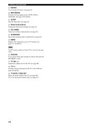
..., DTS or ANALOG). Q TV VOL +/- M VOL MODE Turns on your TV monitor (see page 56). K SLEEP Sets the sleep timer (see pages 88 and 89). P RETURN Use to select sleep timer settings or return to set the TV macro (see page 46). Adjusts the volume level of the TV or the VCR (see... page 60). O MENU Displays the setup menu on or off the volume modes (see pages 31, 62 and 69). Use to the previous SET MENU screen. R CH +/- Note The DVD menu is displayed when DVD is selected as the input source.
..., DTS or ANALOG). Q TV VOL +/- M VOL MODE Turns on your TV monitor (see page 56). K SLEEP Sets the sleep timer (see pages 88 and 89). P RETURN Use to select sleep timer settings or return to set the TV macro (see page 46). Adjusts the volume level of the TV or the VCR (see... page 60). O MENU Displays the setup menu on or off the volume modes (see pages 31, 62 and 69). Use to the previous SET MENU screen. R CH +/- Note The DVD menu is displayed when DVD is selected as the input source.
Owner's Manual
Page 19
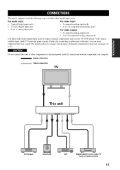
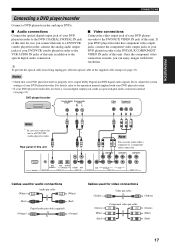
...of audio/video input/output jacks: For audio input • 2 optical digital input jacks • 1 coaxial digital input jack • 2 sets of analog input jacks For video input • 3 composite analog input jacks • 2 sets of component analog input jacks For video output • 1 composite analog ... Audio connection Video connection TV This unit DVD player Subwoofer VCR Digital satellite tuner, cable TV tuner or game console 15 CAUTION Do not connect this unit, you can enjoy reinforced low bass sounds. Further, by connecting a subwoofer to this unit or other ...
...of audio/video input/output jacks: For audio input • 2 optical digital input jacks • 1 coaxial digital input jack • 2 sets of analog input jacks For video input • 3 composite analog input jacks • 2 sets of component analog input jacks For video output • 1 composite analog ... Audio connection Video connection TV This unit DVD player Subwoofer VCR Digital satellite tuner, cable TV tuner or game console 15 CAUTION Do not connect this unit, you can enjoy reinforced low bass sounds. Further, by connecting a subwoofer to this unit or other ...
Owner's Manual
Page 20
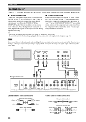
... If you connect this unit COMPONENT COMPONENT COMPONENT DVD COAXIAL AUX TV/STB OPTICAL TV/STB VCR VCR DVD/AUX STB RS-232C REMOTE IN DIGITAL IN AUDIO IN SUBWOOFER VIDEO IN VIDEO OUT Cables used for audio connections (White) Audio pin cable (supplied) (White) (Red) Optical cable... (supplied) (Red) 16 Cables used for easy viewing when you adjust the system parameters in SET MENU. ■ Audio connections ■ Video connections Connect the analog audio output jacks of your TV to the Connect the video input jacks of ...
... If you connect this unit COMPONENT COMPONENT COMPONENT DVD COAXIAL AUX TV/STB OPTICAL TV/STB VCR VCR DVD/AUX STB RS-232C REMOTE IN DIGITAL IN AUDIO IN SUBWOOFER VIDEO IN VIDEO OUT Cables used for audio connections (White) Audio pin cable (supplied) (White) (Red) Optical cable... (supplied) (Red) 16 Cables used for easy viewing when you adjust the system parameters in SET MENU. ■ Audio connections ■ Video connections Connect the analog audio output jacks of your TV to the Connect the video input jacks of ...
Owner's Manual
Page 21
... COMPONENT VCR AUDIO IN jacks of this unit in the supplied cable clamp (see page 21). connection is properly set to output Dolby Digital and DTS digital audio signals. If not, adjust the system settings of your DVD player/recorder. y To prevent the optical cable from being unplugged, affix the optical cable in addition...
... COMPONENT VCR AUDIO IN jacks of this unit in the supplied cable clamp (see page 21). connection is properly set to output Dolby Digital and DTS digital audio signals. If not, adjust the system settings of your DVD player/recorder. y To prevent the optical cable from being unplugged, affix the optical cable in addition...

Owner's Manual
Page 25
... OPTICAL TV/STB VCR VCR DVD/AUX STB RS-232C REMOTE IN DIGITAL IN AUDIO IN SUBWOOFER VIDEO IN VIDEO OUT Cables used for INPUT ASSIGNMENT (see page 77). Optical digital output PREPARATION COMPONENT Rear panel of this unit. CONNECTIONS Connecting other external... components To connect other external components, connect the optical digital output jack of an external component to connect a DVD player/recorder via an optical digital connection, adjust settings for connections Optical cable 21 Note If you connect a DVD player/recorder via...
... OPTICAL TV/STB VCR VCR DVD/AUX STB RS-232C REMOTE IN DIGITAL IN AUDIO IN SUBWOOFER VIDEO IN VIDEO OUT Cables used for INPUT ASSIGNMENT (see page 77). Optical digital output PREPARATION COMPONENT Rear panel of this unit. CONNECTIONS Connecting other external... components To connect other external components, connect the optical digital output jack of an external component to connect a DVD player/recorder via an optical digital connection, adjust settings for connections Optical cable 21 Note If you connect a DVD player/recorder via...

Owner's Manual
Page 26
... unit COMPONENT COMPONENT COMPONENT RS-232C DVD COAXIAL AUX TV/STB OPTICAL REMOTE IN DIGITAL IN TV/STB VCR AUDIO IN VCR SUBWOOFER DVD/AUX STB VIDEO IN VIDEO OUT Cables used for BASS OUT in SUBWOOFER SET (see page 28) or select SWFR for connections Subwoofer pin cable 22 CONNECTIONS Connecting...
... unit COMPONENT COMPONENT COMPONENT RS-232C DVD COAXIAL AUX TV/STB OPTICAL REMOTE IN DIGITAL IN TV/STB VCR AUDIO IN VCR SUBWOOFER DVD/AUX STB VIDEO IN VIDEO OUT Cables used for BASS OUT in SUBWOOFER SET (see page 28) or select SWFR for connections Subwoofer pin cable 22 CONNECTIONS Connecting...

Owner's Manual
Page 29
... SLEEP ST+3BEAM 2 TARGET 5 3BEAM 3 TV 6 MUSIC 7 MOVIE 8 VOL MODE 9 SPORTS 0 OFF +10 SURROUND TV CH LEVEL CINEMA DSP MENU 5 TEST ENTER RETURN 6 7 8 9 1 Input selector buttons 2 YSP 3 Beam mode buttons 4 Sound field program buttons 5 Cursor buttons / / / , ENTER 6 VOL MODE 7 SURROUND 8 MENU 9 RETURN Turning on the power... Press STANDBY/ON on the front panel or on the power of this unit. y You can control other components by setting the appropriate remote control codes (see "Controlling other control buttons on the front panel or on the remote control are operational...
... SLEEP ST+3BEAM 2 TARGET 5 3BEAM 3 TV 6 MUSIC 7 MOVIE 8 VOL MODE 9 SPORTS 0 OFF +10 SURROUND TV CH LEVEL CINEMA DSP MENU 5 TEST ENTER RETURN 6 7 8 9 1 Input selector buttons 2 YSP 3 Beam mode buttons 4 Sound field program buttons 5 Cursor buttons / / / , ENTER 6 VOL MODE 7 SURROUND 8 MENU 9 RETURN Turning on the power... Press STANDBY/ON on the front panel or on the power of this unit. y You can control other components by setting the appropriate remote control codes (see "Controlling other control buttons on the front panel or on the remote control are operational...
Owner's Manual
Page 30
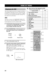
...input jacks of your TV to display the OSD. 1 Check that display the OSD Page 1 Input selector buttons 39 2 TruBass 3 Beam mode buttons 4 Sound field program buttons 5 CH LEVEL 6 VOLUME +/- 7 MUTE 8 INPUTMODE 9 SLEEP 0 VOL MODE A SURROUND B MENU 58 42 51 84 40 41 86 60 56 46 31... AUX VCR INPUT1 STB TV INPUT2 TV MACRO YSP 5BEAM 1 INPUTMODE SLEEP ST+3BEAM 2 3BEAM 3 STEREO TARGET 4 5 6 MUSIC 7 MOVIE 8 VOL MODE 9 SPORTS 0 OFF +10 SURROUND TV CH LEVEL CINEMA DSP MENU TEST ENTER RETURN VOLUME CH TV VOL MUTE TV INPUT TV MUTE CODE SET 8 9 0 A B TV TV AUTO:...
...input jacks of your TV to display the OSD. 1 Check that display the OSD Page 1 Input selector buttons 39 2 TruBass 3 Beam mode buttons 4 Sound field program buttons 5 CH LEVEL 6 VOLUME +/- 7 MUTE 8 INPUTMODE 9 SLEEP 0 VOL MODE A SURROUND B MENU 58 42 51 84 40 41 86 60 56 46 31... AUX VCR INPUT1 STB TV INPUT2 TV MACRO YSP 5BEAM 1 INPUTMODE SLEEP ST+3BEAM 2 3BEAM 3 STEREO TARGET 4 5 6 MUSIC 7 MOVIE 8 VOL MODE 9 SPORTS 0 OFF +10 SURROUND TV CH LEVEL CINEMA DSP MENU TEST ENTER RETURN VOLUME CH TV VOL MUTE TV INPUT TV MUTE CODE SET 8 9 0 A B TV TV AUTO:...
Owner's Manual
Page 31
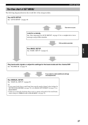
... for a remedy. y • If you want to make additional settings and adjustments Run MANUAL SETUP. SETUP The flow chart of SET MENU The following diagram illustrates the overall flow of the sound beams, adjust settings for the beam mode and the cinema DSP. See "AUTO SETUP" ... there are acoustically absorbent objects such as curtains in the path of the setup procedure. If you cannot clearly hear a sound beam from a specific speaker channel, adjust settings for SETTING PARAMETERS (see page 70) or for BEAM ADJUSTMENT (see page 73). 27 Run BASIC SETUP. See "MANUAL SETUP" ...
... for a remedy. y • If you want to make additional settings and adjustments Run MANUAL SETUP. SETUP The flow chart of SET MENU The following diagram illustrates the overall flow of the sound beams, adjust settings for the beam mode and the cinema DSP. See "AUTO SETUP" ... there are acoustically absorbent objects such as curtains in the path of the setup procedure. If you cannot clearly hear a sound beam from a specific speaker channel, adjust settings for SETTING PARAMETERS (see page 70) or for BEAM ADJUSTMENT (see page 73). 27 Run BASIC SETUP. See "MANUAL SETUP" ...
Owner's Manual
Page 32
...optimizer microphone, allowing you need to set the beam angle to avoid troublesome listening-based speaker setup and achieving highly accurate sound adjustments that each channel so that best match your listening room and broadening the cohesion between speaker channels. EQUALIZING: Adjusts frequency and ...highly precise automatic adjustment of checks to reduce coloration across the channels and create a cohesive sound field. This unit employs the beam optimization feature and the YAMAHA Parametric Room Acoustic Optimizer (YPAO) technology with the aid of each beam from this unit...
...optimizer microphone, allowing you need to set the beam angle to avoid troublesome listening-based speaker setup and achieving highly accurate sound adjustments that each channel so that best match your listening room and broadening the cohesion between speaker channels. EQUALIZING: Adjusts frequency and ...highly precise automatic adjustment of checks to reduce coloration across the channels and create a cohesive sound field. This unit employs the beam optimization feature and the YAMAHA Parametric Room Acoustic Optimizer (YPAO) technology with the aid of each beam from this unit...
Owner's Manual
Page 33
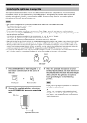
...not properly placed in your listening position. SETUP AUTO SETUP Installing the optimizer microphone The supplied optimizer microphone collects and analyzes the sound that this unit produces in your listening room. Do not place the optimizer microphone to this unit and make sure that ...is completed. • If a subwoofer with the optimizer microphone head upward at the same height as viewed on a conventional clockface and set the volume between the optimizer microphone and the walls in your listening room. Notes • After you have completed the AUTO SETUP procedure...
...not properly placed in your listening position. SETUP AUTO SETUP Installing the optimizer microphone The supplied optimizer microphone collects and analyzes the sound that this unit produces in your listening room. Do not place the optimizer microphone to this unit and make sure that ...is completed. • If a subwoofer with the optimizer microphone head upward at the same height as viewed on a conventional clockface and set the volume between the optimizer microphone and the walls in your listening room. Notes • After you have completed the AUTO SETUP procedure...

Owner's Manual
Page 35
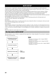
... SETUP procedure. • The AUTO SETUP procedure may not obstruct the path of sound beams. To achieve the best results possible, however, it is normal for appropriate remedies...VCR STB TV AUX INPUT1 INPUT2 MACRO YSP ( ) INPUTMODE SLEEP 5BEAM 1 ST+3BEAM 2 3BEAM 3 STEREO UNIVERSAL 4 5 6 MUSIC 7 MOVIE 8 NIGHT 9 SPORTS 0 OFF +10 SURROUND CH LEVEL CINEMA DSP MENU Notes •...below to start the AUTO SETUP procedure. A set of settings optimized according to specific conditions of your listening environment can save the settings optimized by the AUTO SETUP procedure (see ...
... SETUP procedure. • The AUTO SETUP procedure may not obstruct the path of sound beams. To achieve the best results possible, however, it is normal for appropriate remedies...VCR STB TV AUX INPUT1 INPUT2 MACRO YSP ( ) INPUTMODE SLEEP 5BEAM 1 ST+3BEAM 2 3BEAM 3 STEREO UNIVERSAL 4 5 6 MUSIC 7 MOVIE 8 NIGHT 9 SPORTS 0 OFF +10 SURROUND CH LEVEL CINEMA DSP MENU Notes •...below to start the AUTO SETUP procedure. A set of settings optimized according to specific conditions of your listening environment can save the settings optimized by the AUTO SETUP procedure (see ...