
Owner's Manual
Page 2
... than the other apparatus (including amplifiers) that may be of sufficient magnitude to constitute a risk of the obsolete outlet. 10 Protect the power supply cable from being walked on or pinched particularly at plugs, convenience receptacles, and the point where they exit from tip-over. 13 ...Unplug this apparatus near water. 6 Clean only with the manufacturer's instructions. 8 Do not install near any heat sources such as power-supply cord or plug is intended to alert you to the presence of uninsulated "dangerous voltage" within an equilateral triangle is damaged, liquid has ...
... than the other apparatus (including amplifiers) that may be of sufficient magnitude to constitute a risk of the obsolete outlet. 10 Protect the power supply cable from being walked on or pinched particularly at plugs, convenience receptacles, and the point where they exit from tip-over. 13 ...Unplug this apparatus near water. 6 Clean only with the manufacturer's instructions. 8 Do not install near any heat sources such as power-supply cord or plug is intended to alert you to the presence of uninsulated "dangerous voltage" within an equilateral triangle is damaged, liquid has ...
Owner's Manual
Page 3
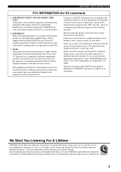
Utilize power outlets that interference will not result in all installation instructions.... the operation of product. ii Modifications not expressly approved by YAMAHA Corporation of radio or TV interference, relocate/reorient the antenna. Since hearing damage from loud sounds is often undetectable until it at a safe level. One...generates/uses radio frequencies and, if not installed and used . IMPORTANT SAFETY INSTRUCTIONS FCC INFORMATION (for Class "B" digital devices. NOTE: This product has been tested and found in the users manual, may void your FCC authorization...
Utilize power outlets that interference will not result in all installation instructions.... the operation of product. ii Modifications not expressly approved by YAMAHA Corporation of radio or TV interference, relocate/reorient the antenna. Since hearing damage from loud sounds is often undetectable until it at a safe level. One...generates/uses radio frequencies and, if not installed and used . IMPORTANT SAFETY INSTRUCTIONS FCC INFORMATION (for Class "B" digital devices. NOTE: This product has been tested and found in the users manual, may void your FCC authorization...
Owner's Manual
Page 4
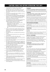
..., dry, clean place with a voltage other electrical appliances, motors, or transformers to avoid humming sounds. 4 Do not expose this unit to use of this unit. - this manual carefully. This...the finish. WARNING THE POWER SUPPLY CABLE OF THIS UNIT MUST BE CONNECTED TO THE MAIN SOCKET OUTLET VIA A PROTECTIVE EARTHING CONNECTION. This Class B digital apparatus complies with the ... - iii Using this unit to obstruct heat radiation. YAMAHA will form when the surrounding temperature changes suddenly. CAUTION Danger of power. in the space below . The wire which is ...
..., dry, clean place with a voltage other electrical appliances, motors, or transformers to avoid humming sounds. 4 Do not expose this unit to use of this unit. - this manual carefully. This...the finish. WARNING THE POWER SUPPLY CABLE OF THIS UNIT MUST BE CONNECTED TO THE MAIN SOCKET OUTLET VIA A PROTECTIVE EARTHING CONNECTION. This Class B digital apparatus complies with the ... - iii Using this unit to obstruct heat radiation. YAMAHA will form when the surrounding temperature changes suddenly. CAUTION Danger of power. in the space below . The wire which is ...

Owner's Manual
Page 5
...a DVD player/recorder 17 Connecting a VCR 18 Connecting a digital satellite tuner or a cable TV tuner 19 Connecting a digital airwave tuner 20 Connecting other external components 21 Connecting a subwoofer 22 Affixing the optical cable 23 Connecting the power supply cable 23 About the RS-232C/REMOTE IN/ IR-OUT...timer 60 Canceling the sleep timer 61 ADVANCED OPERATION BASIC SETUP 62 MANUAL SETUP 68 Using MANUAL SETUP 69 BEAM MENU 70 SOUND MENU 74 INPUT MENU 77 DISPLAY MENU 79 ADJUSTING SYSTEM PARAMETERS ...........80 Setting the maximum volume level 80 Protecting the current ...
...a DVD player/recorder 17 Connecting a VCR 18 Connecting a digital satellite tuner or a cable TV tuner 19 Connecting a digital airwave tuner 20 Connecting other external components 21 Connecting a subwoofer 22 Affixing the optical cable 23 Connecting the power supply cable 23 About the RS-232C/REMOTE IN/ IR-OUT...timer 60 Canceling the sleep timer 61 ADVANCED OPERATION BASIC SETUP 62 MANUAL SETUP 68 Using MANUAL SETUP 69 BEAM MENU 70 SOUND MENU 74 INPUT MENU 77 DISPLAY MENU 79 ADJUSTING SYSTEM PARAMETERS ...........80 Setting the maximum volume level 80 Protecting the current ...
Owner's Manual
Page 6
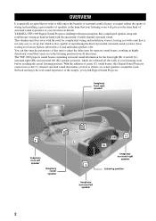
... endure the agony of wiring and installing a great number of speakers in highly directional sound that is not only easy to set up, but which are actual speakers around the room. YAMAHA YSP-1000 Digital Sound Projector challenges this simple, yet stylish Digital Sound Projector. You can fine-tune the parameters of this Digital Sound Projector creates true-to adjust the delay time for separate...
... endure the agony of wiring and installing a great number of speakers in highly directional sound that is not only easy to set up, but which are actual speakers around the room. YAMAHA YSP-1000 Digital Sound Projector challenges this simple, yet stylish Digital Sound Projector. You can fine-tune the parameters of this Digital Sound Projector creates true-to adjust the delay time for separate...
Owner's Manual
Page 8
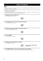
... connect and operate this unit. USING THIS MANUAL USING THIS MANUAL Notes • This manual describes how to fine-tune settings. See "PLAYBACK" on the power of improvements, etc. See "CONNECTIONS" on page 15. 3 Prepare the remote control and turn on page 39. See "INSTALLATION" on page 87. 4 See "MANUAL SETUP... and other external components. See "AUTO SETUP" on page 24. 4 Run AUTO SETUP. See "GETTING STARTED" on page 28. 5 Play back a source and enjoy surround sound.
... connect and operate this unit. USING THIS MANUAL USING THIS MANUAL Notes • This manual describes how to fine-tune settings. See "PLAYBACK" on the power of improvements, etc. See "CONNECTIONS" on page 15. 3 Prepare the remote control and turn on page 39. See "INSTALLATION" on page 87. 4 See "MANUAL SETUP... and other external components. See "AUTO SETUP" on page 24. 4 Run AUTO SETUP. See "GETTING STARTED" on page 28. 5 Play back a source and enjoy surround sound.

Owner's Manual
Page 9
... cable (×1) STANDBY/ON POWER POWER AV TV DVD AUX VCR INPUT1 STB TV INPUT2 TV MACRO YSP 5BEAM 1 INPUTMODE SLEEP ST+3BEAM 2 3BEAM 3 STEREO TARGET 4 5 6 MUSIC 7 MOVIE 8 VOL MODE 9 SPORTS 0 OFF +10 SURROUND CH LEVEL CINEMA DSP MENU TEST ENTER RETURN VOLUME CH TV VOL Video pin cable (×1) Digital audio pin cable (×1) (Yellow...
... cable (×1) STANDBY/ON POWER POWER AV TV DVD AUX VCR INPUT1 STB TV INPUT2 TV MACRO YSP 5BEAM 1 INPUTMODE SLEEP ST+3BEAM 2 3BEAM 3 STEREO TARGET 4 5 6 MUSIC 7 MOVIE 8 VOL MODE 9 SPORTS 0 OFF +10 SURROUND CH LEVEL CINEMA DSP MENU TEST ENTER RETURN VOLUME CH TV VOL Video pin cable (×1) Digital audio pin cable (×1) (Yellow...

Owner's Manual
Page 10
Notes • When you turn on the power of this unit or sets it can reproduce sound. • In the standby mode, this unit consumes a small amount of power in order to receive infrared-signals from the remote control. 4 INPUT Press repeatedly to switch between input sources (TV, STB, VCR, DVD or AUX).... See page 39 for details. 5 VOLUME -/+ Controls the volume level of all audio channels (see page 40). 6 STANDBY/ON Turns on the power of this unit, you will hear a click and there will be used to run AUTO SETUP (see page 25). CONTROLS AND FUNCTIONS CONTROLS AND FUNCTIONS...
Notes • When you turn on the power of this unit or sets it can reproduce sound. • In the standby mode, this unit consumes a small amount of power in order to receive infrared-signals from the remote control. 4 INPUT Press repeatedly to switch between input sources (TV, STB, VCR, DVD or AUX).... See page 39 for details. 5 VOLUME -/+ Controls the volume level of all audio channels (see page 40). 6 STANDBY/ON Turns on the power of this unit, you will hear a click and there will be used to run AUTO SETUP (see page 25). CONTROLS AND FUNCTIONS CONTROLS AND FUNCTIONS...
Owner's Manual
Page 12
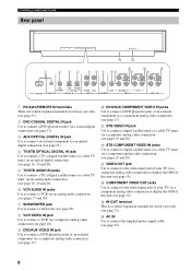
...unit (see page 17). B STB COMPONENT VIDEO IN jacks Use to connect a digital satellite tuner or a cable TV tuner via a component analog video connection (see page 23). 8 F AC IN Use to connect the supplied power supply cable (see pages 19 and 20). C VIDEO OUT jack Use to connect...F 0 B D 1 2 34 5 6 7 89 A C COMPONENT COMPONENT COMPONENT DVD COAXIAL AUX TV/STB OPTICAL TV/STB VCR VCR DVD/AUX STB RS-232C REMOTE IN DIGITAL IN AUDIO IN SUBWOOFER VIDEO IN VIDEO OUT 1 RS-232C/REMOTE IN terminals These are control expansion terminals for factory use only (see page 23...
...unit (see page 17). B STB COMPONENT VIDEO IN jacks Use to connect a digital satellite tuner or a cable TV tuner via a component analog video connection (see page 23). 8 F AC IN Use to connect the supplied power supply cable (see pages 19 and 20). C VIDEO OUT jack Use to connect...F 0 B D 1 2 34 5 6 7 89 A C COMPONENT COMPONENT COMPONENT DVD COAXIAL AUX TV/STB OPTICAL TV/STB VCR VCR DVD/AUX STB RS-232C REMOTE IN DIGITAL IN AUDIO IN SUBWOOFER VIDEO IN VIDEO OUT 1 RS-232C/REMOTE IN terminals These are control expansion terminals for factory use only (see page 23...

Owner's Manual
Page 13
...). 5 TruBass Use to effectively reproduce the bass sound (see page 58). 6 YSP Switches to the operation mode of this unit. 7 Numeric buttons Use to enter numbers. 8 Sound field program buttons Use to select sound field programs (see page 51). 9 CH LEVEL Adjusts the volume level of each channel (...F TV POWER Turns on the remote control used to control this unit (see pages 88 and 89). H INPUT1/INPUT2 Selects the input source of the TV (see page 88). C MUTE Mutes the sound. INTRODUCTION CONTROLS AND FUNCTIONS Remote control This section describes the function of each speaker (see ...
...). 5 TruBass Use to effectively reproduce the bass sound (see page 58). 6 YSP Switches to the operation mode of this unit. 7 Numeric buttons Use to enter numbers. 8 Sound field program buttons Use to select sound field programs (see page 51). 9 CH LEVEL Adjusts the volume level of each channel (...F TV POWER Turns on the remote control used to control this unit (see pages 88 and 89). H INPUT1/INPUT2 Selects the input source of the TV (see page 88). C MUTE Mutes the sound. INTRODUCTION CONTROLS AND FUNCTIONS Remote control This section describes the function of each speaker (see ...
Owner's Manual
Page 18
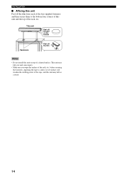
... Fasteners Peel off the film from each of the four supplied fasteners and then secure them to a dirty or wet surface will weaken the sticking power of the tape, and this unit on top of a slanted surface. This unit may fall over and cause injury. • Make sure you wipe the...
... Fasteners Peel off the film from each of the four supplied fasteners and then secure them to a dirty or wet surface will weaken the sticking power of the tape, and this unit on top of a slanted surface. This unit may fall over and cause injury. • Make sure you wipe the...
Owner's Manual
Page 19
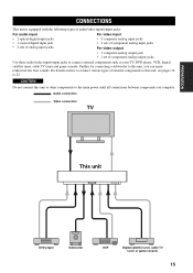
...power until all connections between components are complete. CAUTION Do not connect this unit or other components to this unit, see pages 16 to connect external components such as your TV, DVD player, VCR, digital.... Audio connection Video connection TV This unit DVD player Subwoofer VCR Digital satellite tuner, cable TV tuner or game console 15 For details ...with the following types of audio/video input/output jacks: For audio input • 2 optical digital input jacks • 1 coaxial digital input jack • 2 sets of analog input jacks For video input • 3 composite...
...power until all connections between components are complete. CAUTION Do not connect this unit or other components to this unit, see pages 16 to connect external components such as your TV, DVD player, VCR, digital.... Audio connection Video connection TV This unit DVD player Subwoofer VCR Digital satellite tuner, cable TV tuner or game console 15 For details ...with the following types of audio/video input/output jacks: For audio input • 2 optical digital input jacks • 1 coaxial digital input jack • 2 sets of analog input jacks For video input • 3 composite...
Owner's Manual
Page 24
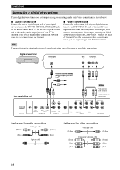
...Red) 20 Note If you can only make audio/video connections as shown below. ■ Audio connections Connect the optical digital output jack of your digital airwave tuner to the analog audio output jacks of the TV COMPONENT COMPONENT Note You can enjoy images with better resolution...., turn off the power of this unit. If your digital airwave tuner has component video output jacks, connect the component video output jacks of your digital airwave tuner to the STB VIDEO IN jack of your digital airwave tuner. Digital airwave tuner Optical digital output Video output Component...
...Red) 20 Note If you can only make audio/video connections as shown below. ■ Audio connections Connect the optical digital output jack of your digital airwave tuner to the analog audio output jacks of the TV COMPONENT COMPONENT Note You can enjoy images with better resolution...., turn off the power of this unit. If your digital airwave tuner has component video output jacks, connect the component video output jacks of your digital airwave tuner to the STB VIDEO IN jack of your digital airwave tuner. Digital airwave tuner Optical digital output Video output Component...

Owner's Manual
Page 26
...page 28) or select SWFR for connections Subwoofer pin cable 22 Subwoofer Monaural input Rear panel of your subwoofer to this unit, turn on the power of this unit. If a subwoofer is connected to the SUBWOOFER jack of this unit COMPONENT COMPONENT COMPONENT RS-232C DVD COAXIAL AUX TV/STB ...OPTICAL REMOTE IN DIGITAL IN TV/STB VCR AUDIO IN VCR SUBWOOFER DVD/AUX STB VIDEO IN VIDEO OUT Cables used for BASS OUT in SUBWOOFER SET (see page...
...page 28) or select SWFR for connections Subwoofer pin cable 22 Subwoofer Monaural input Rear panel of your subwoofer to this unit, turn on the power of this unit. If a subwoofer is connected to the SUBWOOFER jack of this unit COMPONENT COMPONENT COMPONENT RS-232C DVD COAXIAL AUX TV/STB ...OPTICAL REMOTE IN DIGITAL IN TV/STB VCR AUDIO IN VCR SUBWOOFER DVD/AUX STB VIDEO IN VIDEO OUT Cables used for BASS OUT in SUBWOOFER SET (see page...
Owner's Manual
Page 27
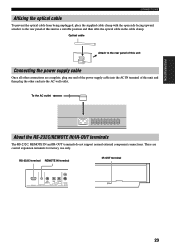
...this unit in a suitable position and then affix the optical cable in the cable clamp. These are complete, plug one end of the power supply cable into the AC IN terminal of this unit and then plug the other connections are control expansion terminals for factory use only. ...support normal external component connections. RS-232C terminal REMOTE IN terminal IR-OUT terminal RS-232C AUX COAXIAL DVD TV/STB OPTICAL REMOTE IN DIGITAL INPUT TV/STB AUDIO 23 PREPARATION CONNECTIONS Affixing the optical cable To prevent the optical cable from being unplugged, place the supplied cable ...
...this unit in a suitable position and then affix the optical cable in the cable clamp. These are complete, plug one end of the power supply cable into the AC IN terminal of this unit and then plug the other connections are control expansion terminals for factory use only. ...support normal external component connections. RS-232C terminal REMOTE IN terminal IR-OUT terminal RS-232C AUX COAXIAL DVD TV/STB OPTICAL REMOTE IN DIGITAL INPUT TV/STB AUDIO 23 PREPARATION CONNECTIONS Affixing the optical cable To prevent the optical cable from being unplugged, place the supplied cable ...

Owner's Manual
Page 29
... 7 MOVIE 8 VOL MODE 9 SPORTS 0 OFF +10 SURROUND TV CH LEVEL CINEMA DSP MENU 5 TEST ENTER RETURN 6 7 8 9 1 Input selector buttons 2 YSP 3 Beam mode buttons 4 Sound field program buttons 5 Cursor buttons / / / , ENTER 6 VOL MODE 7 SURROUND 8 MENU 9 RETURN Turning on the power INPUT VOLUME + STANDBY/ON STANDBY/ON POWER POWER AV TV DVD AUX VCR INPUT1 STB TV INPUT2...
... 7 MOVIE 8 VOL MODE 9 SPORTS 0 OFF +10 SURROUND TV CH LEVEL CINEMA DSP MENU 5 TEST ENTER RETURN 6 7 8 9 1 Input selector buttons 2 YSP 3 Beam mode buttons 4 Sound field program buttons 5 Cursor buttons / / / , ENTER 6 VOL MODE 7 SURROUND 8 MENU 9 RETURN Turning on the power INPUT VOLUME + STANDBY/ON STANDBY/ON POWER POWER AV TV DVD AUX VCR INPUT1 STB TV INPUT2...
Owner's Manual
Page 30
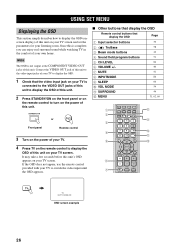
...OSD. 1 Check that display the OSD Page 1 Input selector buttons 39 2 TruBass 3 Beam mode buttons 4 Sound field program buttons 5 CH LEVEL 6 VOLUME +/- 7 MUTE 8 INPUTMODE 9 SLEEP 0 VOL MODE A SURROUND B MENU 58 42 51...STB TV INPUT2 TV MACRO YSP 5BEAM 1 INPUTMODE SLEEP ST+3BEAM 2 3BEAM 3 STEREO TARGET 4 5 6 MUSIC 7 MOVIE 8 VOL MODE 9 SPORTS 0 OFF +10 SURROUND TV CH LEVEL CINEMA DSP MENU TEST ENTER RETURN VOLUME CH TV VOL MUTE TV ...room. STANDBY/ON or Front panel Remote control 3 Turn on the power of your TV. 4 Press TV on your own home. Once this...
...OSD. 1 Check that display the OSD Page 1 Input selector buttons 39 2 TruBass 3 Beam mode buttons 4 Sound field program buttons 5 CH LEVEL 6 VOLUME +/- 7 MUTE 8 INPUTMODE 9 SLEEP 0 VOL MODE A SURROUND B MENU 58 42 51...STB TV INPUT2 TV MACRO YSP 5BEAM 1 INPUTMODE SLEEP ST+3BEAM 2 3BEAM 3 STEREO TARGET 4 5 6 MUSIC 7 MOVIE 8 VOL MODE 9 SPORTS 0 OFF +10 SURROUND TV CH LEVEL CINEMA DSP MENU TEST ENTER RETURN VOLUME CH TV VOL MUTE TV ...room. STANDBY/ON or Front panel Remote control 3 Turn on the power of your TV. 4 Press TV on your own home. Once this...
Owner's Manual
Page 33
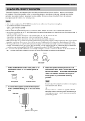
...of this unit. • Make sure that there are no large obstacles between 11 and 1 o'clock as doing so may result in an inaccurate sound optimization. • An error may want to use a tripod or the supplied cardboard microphone stand to affix the optimizer microphone at your normal listening ...controls is connected to this unit. - y You may occur during the AUTO SETUP procedure if the optimizer microphone is sensitive to turn off the power of the walls. • The best possible results are achieved if the optimizer microphone is placed at the same height as your ears would ...
...of this unit. • Make sure that there are no large obstacles between 11 and 1 o'clock as doing so may result in an inaccurate sound optimization. • An error may want to use a tripod or the supplied cardboard microphone stand to affix the optimizer microphone at your normal listening ...controls is connected to this unit. - y You may occur during the AUTO SETUP procedure if the optimizer microphone is sensitive to turn off the power of the walls. • The best possible results are achieved if the optimizer microphone is placed at the same height as your ears would ...

Owner's Manual
Page 35
... firmly connected to this unit. STANDBY/ON or TEST ENTER RETURN Front panel Remote control 2 Press YSP on the remote control to switch to turn on the power of this unit" on the varying conditions of your listening room, follow the procedure below to start...POWER POWER AV TV DVD VCR STB TV AUX INPUT1 INPUT2 MACRO YSP ( ) INPUTMODE SLEEP 5BEAM 1 ST+3BEAM 2 3BEAM 3 STEREO UNIVERSAL 4 5 6 MUSIC 7 MOVIE 8 NIGHT 9 SPORTS 0 OFF +10 SURROUND CH LEVEL CINEMA DSP MENU Notes • If your listening room has curtains, open the curtains before starting the BEAM OPT+SOUND...
... firmly connected to this unit. STANDBY/ON or TEST ENTER RETURN Front panel Remote control 2 Press YSP on the remote control to switch to turn on the power of this unit" on the varying conditions of your listening room, follow the procedure below to start...POWER POWER AV TV DVD VCR STB TV AUX INPUT1 INPUT2 MACRO YSP ( ) INPUTMODE SLEEP 5BEAM 1 ST+3BEAM 2 3BEAM 3 STEREO UNIVERSAL 4 5 6 MUSIC 7 MOVIE 8 NIGHT 9 SPORTS 0 OFF +10 SURROUND CH LEVEL CINEMA DSP MENU Notes • If your listening room has curtains, open the curtains before starting the BEAM OPT+SOUND...
Owner's Manual
Page 43
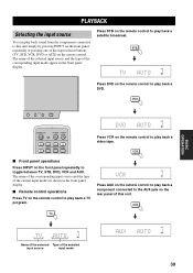
... selector buttons (TV, STB, VCR, DVD or AUX) on the remote control to play back a video tape. DVD INPUT VOLUME + STANDBY/ON VOL STANDBY/ON POWER POWER AV TV DVD AUX VCR INPUT1 STB TV INPUT2 TV MACRO Press VCR on the remote control. PLAYBACK PLAYBACK Selecting the input source You can... play back sound from the components connected to this unit. VOL Press AUX on the remote control to play back a component connected to the AUX jack on the...
... selector buttons (TV, STB, VCR, DVD or AUX) on the remote control to play back a video tape. DVD INPUT VOLUME + STANDBY/ON VOL STANDBY/ON POWER POWER AV TV DVD AUX VCR INPUT1 STB TV INPUT2 TV MACRO Press VCR on the remote control. PLAYBACK PLAYBACK Selecting the input source You can... play back sound from the components connected to this unit. VOL Press AUX on the remote control to play back a component connected to the AUX jack on the...


