
Owner's Manual
Page 1
U RX-V461 AV Receiver OWNER'S MANUAL
U RX-V461 AV Receiver OWNER'S MANUAL

Owner's Manual
Page 2
The safety and operating instructions should be adhered to. 4 Follow Instructions - for future reference. 3 Heed Warnings - The openings should never be retained for example, near a bath tub, wash bowl, kitchen sink, or laundry tub; If the plug should not be located in the operating instructions should be blocked by placing the product on the product and in the vicinity of the polarized plug. 13 Power-Cord Protection - An outside antenna system, extreme care should be routed so that they are provided for long periods of time, unplug it from the type of any kind...
The safety and operating instructions should be adhered to. 4 Follow Instructions - for future reference. 3 Heed Warnings - The openings should never be retained for example, near a bath tub, wash bowl, kitchen sink, or laundry tub; If the plug should not be located in the operating instructions should be blocked by placing the product on the product and in the vicinity of the polarized plug. 13 Power-Cord Protection - An outside antenna system, extreme care should be routed so that they are provided for long periods of time, unplug it from the type of any kind...

Owner's Manual
Page 3
...should be connected to the grounding system of the building, as close to eliminate the problem by the operating instructions as recommended by Yamaha may result in proper operating condition. 22 Wall or Ceiling Mounting - PART H) FCC INFORMATION (for service. 20 Replacement Parts - ...NOTE: This product has been tested and found to be the source of interference, which can not locate the appropriate retailer, please contact Yamaha Electronics Corp., U.S.A. 6660 Orangethorpe Ave., Buena Park, CA 90620. this product to determine that produce heat. Upon completion of antenna ...
...should be connected to the grounding system of the building, as close to eliminate the problem by the operating instructions as recommended by Yamaha may result in proper operating condition. 22 Wall or Ceiling Mounting - PART H) FCC INFORMATION (for service. 20 Replacement Parts - ...NOTE: This product has been tested and found to be the source of interference, which can not locate the appropriate retailer, please contact Yamaha Electronics Corp., U.S.A. 6660 Orangethorpe Ave., Buena Park, CA 90620. this product to determine that produce heat. Upon completion of antenna ...

Owner's Manual
Page 4
...specified is located on switches, knobs and/or cords. 10 When disconnecting the power cable from the wall outlet, grasp the plug; Contact qualified Yamaha service personnel when any damage resulting from the wall outlet. 19 VOLTAGE SELECTOR (Asia and General models only) The VOLTAGE SELECTOR on common operating... de la prise et pousser jusqu'au fond. This unit is connected to obstruct heat radiation. a room with a newspaper, tablecloth, curtain, etc. Yamaha will not be reached easily. 17 Be sure to read this unit is faulty. 18 Before moving this unit, press STANDBY/ON to modify or...
...specified is located on switches, knobs and/or cords. 10 When disconnecting the power cable from the wall outlet, grasp the plug; Contact qualified Yamaha service personnel when any damage resulting from the wall outlet. 19 VOLTAGE SELECTOR (Asia and General models only) The VOLTAGE SELECTOR on common operating... de la prise et pousser jusqu'au fond. This unit is connected to obstruct heat radiation. a room with a newspaper, tablecloth, curtain, etc. Yamaha will not be reached easily. 17 Be sure to read this unit is faulty. 18 Before moving this unit, press STANDBY/ON to modify or...

Owner's Manual
Page 5
... a result of improvements, etc. and Canada models only 13 Information on jacks and cable plugs 14 Connecting video components 15 Connecting audio components 17 Connecting a Yamaha iPod universal dock 18 Using the VIDEO AUX jacks on the front panel .... 18 Connecting the FM and AM antennas 19 Connecting the power cable...
... a result of improvements, etc. and Canada models only 13 Information on jacks and cable plugs 14 Connecting video components 15 Connecting audio components 17 Connecting a Yamaha iPod universal dock 18 Using the VIDEO AUX jacks on the front panel .... 18 Connecting the FM and AM antennas 19 Connecting the power cable...

Owner's Manual
Page 6
... Satellite Radio broadcasts in multi-channels, resulting in a full surround sound experience iPod controlling capability ◆ DOCK terminal to connect a Yamaha iPod universal dock (YDS-10, sold separately), which supports iPod (Click and Wheel), iPod nano, and iPod mini ◆ Playback...◆ Remote control with preset remote control codes Manufactured under license from Dolby Laboratories. We Want You Listening For A Lifetime YAMAHA and the Electronic Industries Association's Consumer Electronics Group want you to get the most importantly, without annoying blaring or distortion -...
... Satellite Radio broadcasts in multi-channels, resulting in a full surround sound experience iPod controlling capability ◆ DOCK terminal to connect a Yamaha iPod universal dock (YDS-10, sold separately), which supports iPod (Click and Wheel), iPod nano, and iPod mini ◆ Playback...◆ Remote control with preset remote control codes Manufactured under license from Dolby Laboratories. We Want You Listening For A Lifetime YAMAHA and the Electronic Industries Association's Consumer Electronics Group want you to get the most importantly, without annoying blaring or distortion -...

Owner's Manual
Page 7
...Select the switch position (upper or lower) according to this unit must be cleared. Notes • Change all of the batteries if you received all of the VOLTAGE SELECTOR may cause damage to your local voltage using a straight slot screwdriver. Improper setting of the following conditions: - ...leaked, dispose of batteries (such as alkaline and manganese batteries) together. dispose of them immediately. Remote control CODE SET TRANSMIT POWER TV POWER AV STANDBY POWER CD DVD DOCK V-AUX MD CD-R CBL DTV MULTI CH IN AUDIO SEL TUNER XM DVR TV VOL TV CH AMP VOLUME...
...Select the switch position (upper or lower) according to this unit must be cleared. Notes • Change all of the batteries if you received all of the VOLTAGE SELECTOR may cause damage to your local voltage using a straight slot screwdriver. Improper setting of the following conditions: - ...leaked, dispose of batteries (such as alkaline and manganese batteries) together. dispose of them immediately. Remote control CODE SET TRANSMIT POWER TV POWER AV STANDBY POWER CD DVD DOCK V-AUX MD CD-R CBL DTV MULTI CH IN AUDIO SEL TUNER XM DVR TV VOL TV CH AMP VOLUME...

Owner's Manual
Page 8
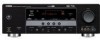
Video monitor Front left speaker Front right speaker Subwoofer Surround right speaker Preparation: Check the items In these steps, you need the following supplied accessories. ❏ Indoor FM antenna ❏ AM loop antenna Center speaker DVD player Surround left speaker Step 1: Set up your speakers ☞ P. 5 Step 2: Connect your home theater. Quick start guide Quick start guide The following steps describe the easiest way to enjoy DVD movie playback in the package of this unit. ❏ Speakers ❏ Front speakers 2 ❏ Center speaker 1 ❏ Surround speakers...
Video monitor Front left speaker Front right speaker Subwoofer Surround right speaker Preparation: Check the items In these steps, you need the following supplied accessories. ❏ Indoor FM antenna ❏ AM loop antenna Center speaker DVD player Surround left speaker Step 1: Set up your speakers ☞ P. 5 Step 2: Connect your home theater. Quick start guide Quick start guide The following steps describe the easiest way to enjoy DVD movie playback in the package of this unit. ❏ Speakers ❏ Front speakers 2 ❏ Center speaker 1 ❏ Surround speakers...
Owner's Manual
Page 9
..., perhaps with a stripe, groove or ridge. Connect the striped (grooved, etc.) cable to the "+" (red) terminals of the speaker cables together to this unit. Subwoofer AV receiver IN MD/ OUT (PLAY) CD-R (REC) OUTPUT SUB WOOFER Input jack Subwoofer cable SUBWOOFER OUTPUT jack English 5 En Front speakers Loosen Insert Tighten To the...
..., perhaps with a stripe, groove or ridge. Connect the striped (grooved, etc.) cable to the "+" (red) terminals of the speaker cables together to this unit. Subwoofer AV receiver IN MD/ OUT (PLAY) CD-R (REC) OUTPUT SUB WOOFER Input jack Subwoofer cable SUBWOOFER OUTPUT jack English 5 En Front speakers Loosen Insert Tighten To the...

Owner's Manual
Page 10
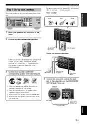
... Digital coaxial audio output jack Digital coaxial audio cable DVD DIGITAL INPUT COAXIAL jack Video input jack Video cable VIDEO MONITOR OUT jack 6 En AV receiver DVD player Make sure that this unit. Composite video output jack Video cable DVD VIDEO jack 1 Connect the digital coaxial audio cable to the... digital coaxial audio output jack of your DVD player and the DVD VIDEO jack of this unit. DVD player AV receiver 3 Connect the video cable to the composite video output jack of your DVD player and the DVD DIGITAL INPUT COAXIAL jack of this unit...
... Digital coaxial audio output jack Digital coaxial audio cable DVD DIGITAL INPUT COAXIAL jack Video input jack Video cable VIDEO MONITOR OUT jack 6 En AV receiver DVD player Make sure that this unit. Composite video output jack Video cable DVD VIDEO jack 1 Connect the digital coaxial audio cable to the... digital coaxial audio output jack of your DVD player and the DVD VIDEO jack of this unit. DVD player AV receiver 3 Connect the video cable to the composite video output jack of your DVD player and the DVD DIGITAL INPUT COAXIAL jack of this unit...

Owner's Manual
Page 11
..., 16 • Connecting a CD player and an MD recorder ☞ P. 17 • Connecting a DVD player via analog multi-channel audio connection ☞ P. 17 • Connecting a Yamaha iPod universal dock ☞ P. 18 • Using the VIDEO AUX jacks on the front panel ☞ P. 18 • Connecting an outdoor FM/AM antenna ☞...
..., 16 • Connecting a CD player and an MD recorder ☞ P. 17 • Connecting a DVD player via analog multi-channel audio connection ☞ P. 17 • Connecting a Yamaha iPod universal dock ☞ P. 18 • Using the VIDEO AUX jacks on the front panel ☞ P. 18 • Connecting an outdoor FM/AM antenna ☞...

Owner's Manual
Page 12
Press FSCENE 3 (or FSCENE 3) to this unit automatically optimize own status for details. y The indicator on the selected SCENE button lights up while this room..." "DVD Viewing" appears in the front panel display, and this unit in the SCENE mode. 8 En Case A: "I want to listen to select "Disc Listening". If the speakers are 6 ohm speakers, set "SP IMP." Case B: "I want to watch a TV program..." Note To use the "TV Viewing" template (Case B), you change the input source or sound field program, the SCENE mode is in advance. Quick start guide Step 3: Turn on the ...
Press FSCENE 3 (or FSCENE 3) to this unit automatically optimize own status for details. y The indicator on the selected SCENE button lights up while this room..." "DVD Viewing" appears in the front panel display, and this unit in the SCENE mode. 8 En Case A: "I want to listen to select "Disc Listening". If the speakers are 6 ohm speakers, set "SP IMP." Case B: "I want to watch a TV program..." Note To use the "TV Viewing" template (Case B), you change the input source or sound field program, the SCENE mode is in advance. Quick start guide Step 3: Turn on the ...

Owner's Manual
Page 13
...; To achieve the best possible reception, orient the connected AM loop antenna, or adjust the position of the end of power in order to receive infrared signals from the remote control. Press 1STANDBY/ON on this unit consumes a small amount of the indoor FM antenna. See page 19 for...speaker parameters for the high fidelity sound ☞ P. 32 • Customizing the sound field programs ☞ P. 37 This unit is set this unit to receive infrared signals from the standby mode, press 1STANDBY/ ON (or GSTANDBY). Quick start guide What do with this unit. ☞ P. 46 ■ Using ...
...; To achieve the best possible reception, orient the connected AM loop antenna, or adjust the position of the end of power in order to receive infrared signals from the remote control. Press 1STANDBY/ON on this unit consumes a small amount of the indoor FM antenna. See page 19 for...speaker parameters for the high fidelity sound ☞ P. 32 • Customizing the sound field programs ☞ P. 37 This unit is set this unit to receive infrared signals from the standby mode, press 1STANDBY/ ON (or GSTANDBY). Quick start guide What do with this unit. ☞ P. 46 ■ Using ...

Owner's Manual
Page 14
A B (U.S.A. and Canada models only) See page 41 for connection information. 3 COMPONENT VIDEO jacks See page 16 for connection information. 4 VIDEO jacks See pages 15 and 16 for connection information. 5 ANTENNA terminals See page 19 for connection information. 6 SPEAKERS terminals See page 12 for connection information. 7 AC OUTLET(S) See page 19 for connection information. 8 DIGITAL INPUT jacks See pages 15 and 17 for connection information. 9 MULTI CH INPUT jacks See page 17 for connection information. A SUBWOOFER OUTPUT jack See page 12 for connection information. B VOLTAGE ...
A B (U.S.A. and Canada models only) See page 41 for connection information. 3 COMPONENT VIDEO jacks See page 16 for connection information. 4 VIDEO jacks See pages 15 and 16 for connection information. 5 ANTENNA terminals See page 19 for connection information. 6 SPEAKERS terminals See page 12 for connection information. 7 AC OUTLET(S) See page 19 for connection information. 8 DIGITAL INPUT jacks See pages 15 and 17 for connection information. 9 MULTI CH INPUT jacks See page 17 for connection information. A SUBWOOFER OUTPUT jack See page 12 for connection information. B VOLTAGE ...

Owner's Manual
Page 15
... sounds (dialog, vocals, etc.). The distance of each speaker from each side of the LFE (low-frequency effect) channel included in amplifier, such as the Yamaha Active Servo Processing Subwoofer System, is better to enjoy CINEMA DSP and multichannel audio sources. But it is for reinforcing bass frequencies from the ideal...
... sounds (dialog, vocals, etc.). The distance of each speaker from each side of the LFE (low-frequency effect) channel included in amplifier, such as the Yamaha Active Servo Processing Subwoofer System, is better to enjoy CINEMA DSP and multichannel audio sources. But it is for reinforcing bass frequencies from the ideal...

Owner's Manual
Page 16
Surround speakers Right Left Front speakers (B) Right Left Center speaker Subwoofer Center speaker XM ANTENNA SPEAKERS DOCK COMPONENT VIDEO DVD DTV/CBL DVR MONITOR OUT DVD VIDEO DTV/CBL IN DVR OUT MONITOR OUT PR DIGITAL INPUT PB S VIDEO OPTICAL CD 3 Y DTV/ CBL 2 MULTI CH INPUT FRONT SURROUND CENTER L VIDEO DVD DTV/CBL L AUDIO IN DVR OUT CD DVD 1 R COAXIAL R SUBWOOFER AM GND FM 75 UNBAL. If the connections are to use 6 ohm speakers, be sure to set "SP IMP." Note A speaker cord is turned off (see page 19). • Do not let the bare speaker wires ...
Surround speakers Right Left Front speakers (B) Right Left Center speaker Subwoofer Center speaker XM ANTENNA SPEAKERS DOCK COMPONENT VIDEO DVD DTV/CBL DVR MONITOR OUT DVD VIDEO DTV/CBL IN DVR OUT MONITOR OUT PR DIGITAL INPUT PB S VIDEO OPTICAL CD 3 Y DTV/ CBL 2 MULTI CH INPUT FRONT SURROUND CENTER L VIDEO DVD DTV/CBL L AUDIO IN DVR OUT CD DVD 1 R COAXIAL R SUBWOOFER AM GND FM 75 UNBAL. If the connections are to use 6 ohm speakers, be sure to set "SP IMP." Note A speaker cord is turned off (see page 19). • Do not let the bare speaker wires ...

Owner's Manual
Page 17
Remove approximately 10 mm (3/8") of insulation from the end of each speaker cable and then twist the bare wires of the speaker wire into the end of insulated cables running side by side. SP IMP.- 8 MIN 1 Loosen the knob. 2 Insert the bare end of the cable together to prevent short circuits. Banana plug SP IMP.- 6 MIN 5 Press 1STANDBY/ON to confirm your speaker. and Canada models only) Caution If you turn on the terminal. 3 Tighten the knob to secure the wire. 4 Press BSTRAIGHT repeatedly to select "6Ω MIN". Note The setting you made is reflected next time you are ...
Remove approximately 10 mm (3/8") of insulation from the end of each speaker cable and then twist the bare wires of the speaker wire into the end of insulated cables running side by side. SP IMP.- 8 MIN 1 Loosen the knob. 2 Insert the bare end of the cable together to prevent short circuits. Banana plug SP IMP.- 6 MIN 5 Press 1STANDBY/ON to confirm your speaker. and Canada models only) Caution If you turn on the terminal. 3 Tighten the knob to secure the wire. 4 Press BSTRAIGHT repeatedly to select "6Ω MIN". Note The setting you made is reflected next time you are ...

Owner's Manual
Page 18
When you connect the fiber optic cable. VIDEO jacks For conventional composite video signals transmitted via coaxial digital audio cables. Video signal flow for MONITOR OUT Input Output (MONITOR OUT) PR PR COMPONENT VIDEO PB PB Y Y S VIDEO VIDEO Note The OSD signal is not output at the analog AUDIO OUT (REC) jacks. • Pull out the cap from dust. ■ Video jacks This unit has three types of video jacks. DIGITAL AUDIO COAXIAL jacks For digital audio signals transmitted via composite video cables. S VIDEO jacks For S-video signals, separated into the ...
When you connect the fiber optic cable. VIDEO jacks For conventional composite video signals transmitted via coaxial digital audio cables. Video signal flow for MONITOR OUT Input Output (MONITOR OUT) PR PR COMPONENT VIDEO PB PB Y Y S VIDEO VIDEO Note The OSD signal is not output at the analog AUDIO OUT (REC) jacks. • Pull out the cap from dust. ■ Video jacks This unit has three types of video jacks. DIGITAL AUDIO COAXIAL jacks For digital audio signals transmitted via composite video cables. S VIDEO jacks For S-video signals, separated into the ...

Owner's Manual
Page 19
Connections Make sure that this unit using the S VIDEO or COMPONENT VIDEO connections (see page 16). PREPARATION Connecting video components Connect the video components as follows. y You can also connect a video monitor, DVD player, digital TV, and cable TV to this unit and other components are unplugged from the AC wall outlets. ■ Connecting a video monitor and a DVD player ■ Connecting a cable TV/satellite tuner and a DVD recorder XM DOCK COMPONENT VIDEO DVD DTV/CBL DVR MONITOR OUT DVD VIDEO DTV/CBL IN DVR OUT MONITOR OUT PR DIGITAL INPUT PB S VIDEO OPTICAL...
Connections Make sure that this unit using the S VIDEO or COMPONENT VIDEO connections (see page 16). PREPARATION Connecting video components Connect the video components as follows. y You can also connect a video monitor, DVD player, digital TV, and cable TV to this unit and other components are unplugged from the AC wall outlets. ■ Connecting a video monitor and a DVD player ■ Connecting a cable TV/satellite tuner and a DVD recorder XM DOCK COMPONENT VIDEO DVD DTV/CBL DVR MONITOR OUT DVD VIDEO DTV/CBL IN DVR OUT MONITOR OUT PR DIGITAL INPUT PB S VIDEO OPTICAL...

Owner's Manual
Page 20
COMPONENT VIDEO connection S VIDEO connection DVD player Video monitor Cable TV or satellite tuner Video monitor Video out Video in Video out Video in Video out Video out Video out Video out Video in the same way you connect your video monitor to this unit using a COMPONENT VIDEO connection, connect your video components to this unit. For example, if you connect your video monitor to this unit using COMPONENT VIDEO or S VIDEO connections. Note Be sure to connect your video components in Y PB PR Y PB PR COMPONENT VIDEO DVD DTV/CBL DVR MONITOR OUT PR PB Y MULTI CH ...
COMPONENT VIDEO connection S VIDEO connection DVD player Video monitor Cable TV or satellite tuner Video monitor Video out Video in Video out Video in Video out Video out Video out Video out Video in the same way you connect your video monitor to this unit using a COMPONENT VIDEO connection, connect your video components to this unit. For example, if you connect your video monitor to this unit using COMPONENT VIDEO or S VIDEO connections. Note Be sure to connect your video components in Y PB PR Y PB PR COMPONENT VIDEO DVD DTV/CBL DVR MONITOR OUT PR PB Y MULTI CH ...
