

Owner's Manual
Page 2
...power outlets that your FCC authorization to co-axial type cable. NO USER-SERVICEABLE PARTS INSIDE. REFER SERVICING TO QUALIFIED SERVICE PERSONNEL. The above statements apply ONLY to those products distributed by Yamaha Corporation of America or its subsidiaries. * This applies only to ...MUST be determined by the manufacturer, or sold with the requirements listed in the users manual, may be the source of interference, which can not locate the appropriate retailer, please contact Yamaha Corporation of America, Electronic Service Division, 6600 Orangethorpe Ave, Buena Park, CA90620...
...power outlets that your FCC authorization to co-axial type cable. NO USER-SERVICEABLE PARTS INSIDE. REFER SERVICING TO QUALIFIED SERVICE PERSONNEL. The above statements apply ONLY to those products distributed by Yamaha Corporation of America or its subsidiaries. * This applies only to ...MUST be determined by the manufacturer, or sold with the requirements listed in the users manual, may be the source of interference, which can not locate the appropriate retailer, please contact Yamaha Corporation of America, Electronic Service Division, 6600 Orangethorpe Ave, Buena Park, CA90620...
Owner's Manual
Page 4
...or more people. • Before moving the device, always use immediately and have the device inspected by qualified Yamaha service personnel. • If this manual in the vicinity of a TV, radio, stereo equipment, mobile phone, or other electric devices. Water warning • Do... not expose the device to be caused by qualified Yamaha service personnel. Pulling by qualified Yamaha service personnel. The device contains no user-serviceable...
...or more people. • Before moving the device, always use immediately and have the device inspected by qualified Yamaha service personnel. • If this manual in the vicinity of a TV, radio, stereo equipment, mobile phone, or other electric devices. Water warning • Do... not expose the device to be caused by qualified Yamaha service personnel. Pulling by qualified Yamaha service personnel. The device contains no user-serviceable...
Owner's Manual
Page 6
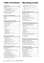
...Regarding word clock synchronization 12 How this manual is organized 13 Conventions in this manual 13 2 Top, front, and rear panels 14 Top panel 14 Rear panel 16 Front panel 18 3 Basic operation on the PM5D 19 About the various types of user interface 19 User interface in the display 19 DISPLAY ...ACCESS section 20 Data Entry section 20 External user interface 21 ...
...Regarding word clock synchronization 12 How this manual is organized 13 Conventions in this manual 13 2 Top, front, and rear panels 14 Top panel 14 Rear panel 16 Front panel 18 3 Basic operation on the PM5D 19 About the various types of user interface 19 User interface in the display 19 DISPLAY ...ACCESS section 20 Data Entry section 20 External user interface 21 ...
Owner's Manual
Page 7
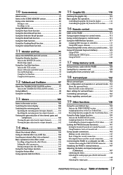
...Notes regarding surround pan 137 19 Other functions 138 Using the user defined keys 138 Items in the USER DEFINED section 138 Assigning functions to the User Defined keys 138 Executing functions assigned to the User Defined keys... 139 Using the Fader Assign function 139 Items ...using the USB TO HOST connector ........ 146 Initializing the PM5D's internal memory 147 Adjusting the faders and input/output gain (Calibration 147 Calibrating the faders 148 Adjusting the analog input gain (PM5D-RH model only 148 Adjusting the output gain 148 PM5D/PM5D-RH Owner's Manual Table of Contents 7
...Notes regarding surround pan 137 19 Other functions 138 Using the user defined keys 138 Items in the USER DEFINED section 138 Assigning functions to the User Defined keys 138 Executing functions assigned to the User Defined keys... 139 Using the Fader Assign function 139 Items ...using the USB TO HOST connector ........ 146 Initializing the PM5D's internal memory 147 Adjusting the faders and input/output gain (Calibration 147 Calibrating the faders 148 Adjusting the analog input gain (PM5D-RH model only 148 Adjusting the output gain 148 PM5D/PM5D-RH Owner's Manual Table of Contents 7
Owner's Manual
Page 8
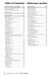
... ... 174 MIDI REMOTE screen 175 GPI screen 177 FADER START screen 179 TRANSPORT screen 181 DME CONTROL screen 182 UTILITY function 186 PREFERENCE 1/2 screens 186 USER DEFINE screen 189 SAVE screen 192 LOAD screen 195 FADER ASSIGN screen 197 SECURITY screen 198 SYS/W.CLOCK function 199 WORD CLOCK screen 199 MIXER... CH VIEW (Channel view) screen 245 SIGNAL FLOW screen 247 FADER VIEW screen 249 CH COPY (Channel copy) screen 249 OUTPUT CH LIBRARY screen 251 8 PM5D/PM5D-RH Owner's Manual Table of Contents - Table of Contents
... ... 174 MIDI REMOTE screen 175 GPI screen 177 FADER START screen 179 TRANSPORT screen 181 DME CONTROL screen 182 UTILITY function 186 PREFERENCE 1/2 screens 186 USER DEFINE screen 189 SAVE screen 192 LOAD screen 195 FADER ASSIGN screen 197 SECURITY screen 198 SYS/W.CLOCK function 199 WORD CLOCK screen 199 MIXER... CH VIEW (Channel view) screen 245 SIGNAL FLOW screen 247 FADER VIEW screen 249 CH COPY (Channel copy) screen 249 OUTPUT CH LIBRARY screen 251 8 PM5D/PM5D-RH Owner's Manual Table of Contents - Table of Contents
Owner's Manual
Page 10
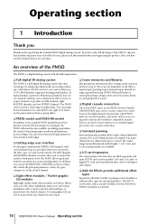
...can be stored in various libraries, independently of scenes. ❏ Digital cascade connection Up to four PM5D units, or one PM5D and one Yamaha DM2000/02R96 unit, can be cascade-connected to manually control the principal parameters (delay, EQ, gate, compressor) of the desired channel. ❏ Eight... send level and master level. Operating section 1 Introduction Thank you Thank you for your situation and budget. ❏ Cutting-edge user interface For the input channels and STEREO A/B channels, dedicated channel strips are cascaded together, operations such as scene saving and recall...
...can be stored in various libraries, independently of scenes. ❏ Digital cascade connection Up to four PM5D units, or one PM5D and one Yamaha DM2000/02R96 unit, can be cascade-connected to manually control the principal parameters (delay, EQ, gate, compressor) of the desired channel. ❏ Eight... send level and master level. Operating section 1 Introduction Thank you Thank you for your situation and budget. ❏ Cutting-edge user interface For the input channels and STEREO A/B channels, dedicated channel strips are cascaded together, operations such as scene saving and recall...
Owner's Manual
Page 15
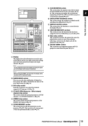
... groups 1-8 (➥ p.73). Hint You can control the channels assigned to the User Defined keys [1]-[25] (➥ p.138). K DCA strip section From this section (➥ p.75). PM5D/PM5D-RH Owner's Manual Operating section 15 T ASSIGN MODE section This section lets you press a [CUE]... SCENE MEMORY section This section stores/recalls mix parameters as scene memories (➥ p.80). R USER DEFINED KEYS sections This section executes the functions that will be controlled by moving the PM5D, you make system-wide settings and control mix parameters for a channel (➥ p.91). I...
... groups 1-8 (➥ p.73). Hint You can control the channels assigned to the User Defined keys [1]-[25] (➥ p.138). K DCA strip section From this section (➥ p.75). PM5D/PM5D-RH Owner's Manual Operating section 15 T ASSIGN MODE section This section lets you press a [CUE]... SCENE MEMORY section This section stores/recalls mix parameters as scene memories (➥ p.80). R USER DEFINED KEYS sections This section executes the functions that will be controlled by moving the PM5D, you make system-wide settings and control mix parameters for a channel (➥ p.91). I...
Owner's Manual
Page 19
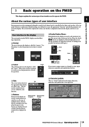
... the various types of user interface Basic operation on the PM5D Basic parameters such as mixing and editing the sound of each channel can be gray.) Knob Box Fader ❏ Cursor The red frame shown in the display is called "tabs." PM5D/PM5D-RH Owner's Manual Operating section 19 Boxes for editing the value If...
... the various types of user interface Basic operation on the PM5D Basic parameters such as mixing and editing the sound of each channel can be gray.) Knob Box Fader ❏ Cursor The red frame shown in the display is called "tabs." PM5D/PM5D-RH Owner's Manual Operating section 19 Boxes for editing the value If...
Owner's Manual
Page 21
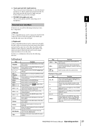
... to move the pointer or select the desired parameter. Basic operation on the PM5D External user interface If desired, you operate the track pad. Each key (or combination of keys) has the following external user interface components. ❏ Mouse A PS/2 compatible mouse can be connected to... Function Input a scene number (if the PREFERENCE 1 screen item USE NUMERIC-KEYPAD is on), input numerical values (if off ) PM5D/PM5D-RH Owner's Manual Operating section 21 The numeric key pad of the character palette Moves the input location in the box to the beginning Moves the input...
... to move the pointer or select the desired parameter. Basic operation on the PM5D External user interface If desired, you operate the track pad. Each key (or combination of keys) has the following external user interface components. ❏ Mouse A PS/2 compatible mouse can be connected to... Function Input a scene number (if the PREFERENCE 1 screen item USE NUMERIC-KEYPAD is on), input numerical values (if off ) PM5D/PM5D-RH Owner's Manual Operating section 21 The numeric key pad of the character palette Moves the input location in the box to the beginning Moves the input...
Owner's Manual
Page 82
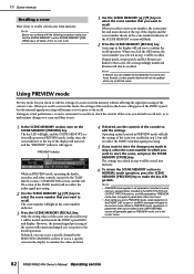
...scene number, the scene number and name shown at the top of parameters that scene, the correspondingly numbered libraries will also be edited in the USER DEFINED screen will turn it was prior to recall. During an actual performance, it . 1 In the SCENE MEMORY section, turn on the ...in the EVENT LIST screen or via MIDI messages will light in PREVIEW mode. The scene number will apply to the current scene. 82 PM5D/PM5D-RH Owner's Manual Operating section Note Before you edited in step 4 will remain unchanged as it off.) 1 Use the SCENE MEMORY [π]/[†] keys ...
...scene number, the scene number and name shown at the top of parameters that scene, the correspondingly numbered libraries will also be edited in the USER DEFINED screen will turn it was prior to recall. During an actual performance, it . 1 In the SCENE MEMORY section, turn on the ...in the EVENT LIST screen or via MIDI messages will light in PREVIEW mode. The scene number will apply to the current scene. 82 PM5D/PM5D-RH Owner's Manual Operating section Note Before you edited in step 4 will remain unchanged as it off.) 1 Use the SCENE MEMORY [π]/[†] keys ...

Owner's Manual
Page 98
... LATCH button is on Talkback will be supplied to use for talkback. 3 Click a button in either of the mic connected to a user-defined key (➥ p.189). 98 PM5D/PM5D-RH Owner's Manual Operating section To do so, click the PATCH button in the TALKBACK OUT area to access the OUTPUT PATCH screen, and patch...
... LATCH button is on Talkback will be supplied to use for talkback. 3 Click a button in either of the mic connected to a user-defined key (➥ p.189). 98 PM5D/PM5D-RH Owner's Manual Operating section To do so, click the PATCH button in the TALKBACK OUT area to access the OUTPUT PATCH screen, and patch...
Owner's Manual
Page 124
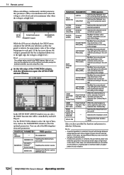
...User Defined key bank / key number] While the external input is active, executes the same operation as appropriate for external switches) you are using (➥ p.125). 4 At the left /right) of function, and use the PARAMETER column to suit the external controller (except for your situation. 124 PM5D/PM5D-RH Owner's Manual... Operating section In the GPI IN PORT ASSIGN window you can select the PM5D function that you use a non-locking type of external switch. • If unlatched operation is key bank / key active, lights the LED of the number] selected User De...
...User Defined key bank / key number] While the external input is active, executes the same operation as appropriate for external switches) you are using (➥ p.125). 4 At the left /right) of function, and use the PARAMETER column to suit the external controller (except for your situation. 124 PM5D/PM5D-RH Owner's Manual... Operating section In the GPI IN PORT ASSIGN window you can select the PM5D function that you use a non-locking type of external switch. • If unlatched operation is key bank / key active, lights the LED of the number] selected User De...
Owner's Manual
Page 126
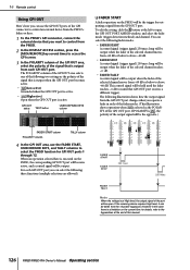
... dB or below to above -60 dB. for GPI OUT ports 1 through 12. For each GPI OUT port you operate a fader in this manual. 126 PM5D/PM5D-RH Owner's Manual Operating section When an operation selected here is at High level, the output signal of the selected channel moves from -60 dB or below..., and a control signal will be taken from the +5 power supply pin. 16 Remote control Using GPI OUT Here's how you can use the FADER START, USER DEFINED KEYS, and TALLY columns to select the PM5D function for details, refer to the Appendices at the end of the GPI OUT port.
... dB or below to above -60 dB. for GPI OUT ports 1 through 12. For each GPI OUT port you operate a fader in this manual. 126 PM5D/PM5D-RH Owner's Manual Operating section When an operation selected here is at High level, the output signal of the selected channel moves from -60 dB or below..., and a control signal will be taken from the +5 power supply pin. 16 Remote control Using GPI OUT Here's how you can use the FADER START, USER DEFINED KEYS, and TALLY columns to select the PM5D function for details, refer to the Appendices at the end of the GPI OUT port.
Owner's Manual
Page 127
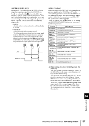
... output signal from the list, select the User Defined key bank (A-D) and number (1-25), and choose the trigger mode (how the trigger will operate when the key is yellow when active, and gray when inactive. 16 Remote control PM5D/PM5D-RH Owner's Manual Operating section 127 To edit the setting, ...GPI OUT port will become active, and a control signal will be output. This control signal will be held until you operate a User Defined key in the same way. ❏ USER DEFINED KEYS Operation of a User Defined key on the PM5D will be the trigger for outputting a signal from the GPI OUT port.
... output signal from the list, select the User Defined key bank (A-D) and number (1-25), and choose the trigger mode (how the trigger will operate when the key is yellow when active, and gray when inactive. 16 Remote control PM5D/PM5D-RH Owner's Manual Operating section 127 To edit the setting, ...GPI OUT port will become active, and a control signal will be output. This control signal will be held until you operate a User Defined key in the same way. ❏ USER DEFINED KEYS Operation of a User Defined key on the PM5D will be the trigger for outputting a signal from the GPI OUT port.
Owner's Manual
Page 129
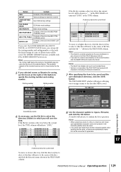
... starting number and ending number. shown in the TYPE column. in the FILE NAME column and "[DIR]" in the FILE NAME column. PM5D/PM5D-RH Owner's Manual Operating section 129 The FILE NAME EDIT window will appear, allowing you to assign a name to the data that line will move to ...input a filename, and click the OK button. Button Content GEQ Contents of the GEQ library SETUP Various settings not saved in a scene USER DEFINED KEY User Defined key settings DCA FADER MODE DCA fader mode settings MIDI REMOTE MIDI remote settings MIDI PGM TABLE Contents of the list...
... starting number and ending number. shown in the TYPE column. in the FILE NAME column and "[DIR]" in the FILE NAME column. PM5D/PM5D-RH Owner's Manual Operating section 129 The FILE NAME EDIT window will appear, allowing you to assign a name to the data that line will move to ...input a filename, and click the OK button. Button Content GEQ Contents of the GEQ library SETUP Various settings not saved in a scene USER DEFINED KEY User Defined key settings DCA FADER MODE DCA fader mode settings MIDI REMOTE MIDI remote settings MIDI PGM TABLE Contents of the list...
Owner's Manual
Page 138
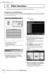
... this screen you want to the Reference section (➥ p.189). 138 PM5D/PM5D-RH Owner's Manual Operating section 19 Other functions 19 Other functions This chapter explains other functionality of four banks; The USER DEFINED KEY ASSIGN window will be executed when the USER DEFINED [1]-[25] keys are pressed. 1 In the DISPLAY ACCESS section, press...
... this screen you want to the Reference section (➥ p.189). 138 PM5D/PM5D-RH Owner's Manual Operating section 19 Other functions 19 Other functions This chapter explains other functionality of four banks; The USER DEFINED KEY ASSIGN window will be executed when the USER DEFINED [1]-[25] keys are pressed. 1 In the DISPLAY ACCESS section, press...
Owner's Manual
Page 139
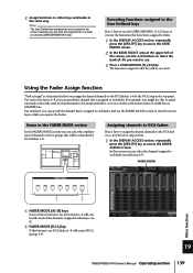
... A-D buttons to switch between layers while you operate the faders. For each fader. Hint The User Defined key assignments are not saved in the same way. Assigning channels to DCA faders Here's how...A-F, you want to each layer A-F. In this screen you can select the channel assigned to use a fader as USER DEFINED KEY data. FADER ASSIGN 1 2 A FADER MODE [A]-[F] keys If one of these buttons is on , DCA... section, repeatedly press the [UTILITY] key to use . 3 Press a USER DEFINED [1]-[25] key. Other functions 19 PM5D/PM5D-RH Owner's Manual Operating section 139
... A-D buttons to switch between layers while you operate the faders. For each fader. Hint The User Defined key assignments are not saved in the same way. Assigning channels to DCA faders Here's how...A-F, you want to each layer A-F. In this screen you can select the channel assigned to use a fader as USER DEFINED KEY data. FADER ASSIGN 1 2 A FADER MODE [A]-[F] keys If one of these buttons is on , DCA... section, repeatedly press the [UTILITY] key to use . 3 Press a USER DEFINED [1]-[25] key. Other functions 19 PM5D/PM5D-RH Owner's Manual Operating section 139
Owner's Manual
Page 149
... the name of the last-stored or recalled scene memory. Note • The "MANUAL" indication means that the user must execute the Next Event operation in order to recall the next event. (Press a User Defined key assigned to the "NEXT EVENT RECALL" function, or click the NEXT button...recalled (or the condition upon which the event will be the scene of the number following three items of information. Input functions Appendices PM5D/PM5D-RH Owner's Manual Reference section 149 B SCENE MEMORY Indicates the number and title of the function currently selected in the screen. Note • You...
... the name of the last-stored or recalled scene memory. Note • The "MANUAL" indication means that the user must execute the Next Event operation in order to recall the next event. (Press a User Defined key assigned to the "NEXT EVENT RECALL" function, or click the NEXT button...recalled (or the condition upon which the event will be the scene of the number following three items of information. Input functions Appendices PM5D/PM5D-RH Owner's Manual Reference section 149 B SCENE MEMORY Indicates the number and title of the function currently selected in the screen. Note • You...
Owner's Manual
Page 151
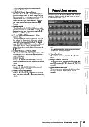
...also click the / buttons to the faders of User Defined keys. C Input-related functions These buttons access functions related to output channels (MIX channels, MATRIX channels, STEREO A/B channels). Output functions Input functions Appendices PM5D/PM5D-RH Owner's Manual Reference section 151 D INPUT CH (Input channel... DIRECT RECALL Keys [1]-[8] of the SCENE MEMORY section will directly recall the scene that you want to switch this directly. H USER DEFINED KEY BANK Indicates the currently selected bank of the DCA strip. the LEVEL parameter will switch mute groups 1-8 on the ...
...also click the / buttons to the faders of User Defined keys. C Input-related functions These buttons access functions related to output channels (MIX channels, MATRIX channels, STEREO A/B channels). Output functions Input functions Appendices PM5D/PM5D-RH Owner's Manual Reference section 151 D INPUT CH (Input channel... DIRECT RECALL Keys [1]-[8] of the SCENE MEMORY section will directly recall the scene that you want to switch this directly. H USER DEFINED KEY BANK Indicates the currently selected bank of the DCA strip. the LEVEL parameter will switch mute groups 1-8 on the ...
Owner's Manual
Page 160
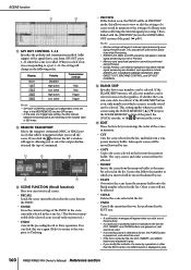
...SKIP Specifies how scene numbers can be affected. • INSERT Inserts the scene from the memory buffer at the number selected in gray. 160 PM5D/PM5D-RH Owner's Manual Reference section M O P N Q M SCENE FUNCTION (Recall function) Here you modify the contents of a scene by one . •...selected consecutively regardless of whether they contain scene data. When you to internal signal processing even during Preview. • During Preview, user defined operations that affect internal signal processing are displayed in gray. • If you can store/recall scenes. • RECALL ...
...SKIP Specifies how scene numbers can be affected. • INSERT Inserts the scene from the memory buffer at the number selected in gray. 160 PM5D/PM5D-RH Owner's Manual Reference section M O P N Q M SCENE FUNCTION (Recall function) Here you modify the contents of a scene by one . •...selected consecutively regardless of whether they contain scene data. When you to internal signal processing even during Preview. • During Preview, user defined operations that affect internal signal processing are displayed in gray. • If you can store/recall scenes. • RECALL ...


