
Owner's Manual
Page 1
U B NS-P230/ NS-P236 (NS-P230/NS-P236: NX-230P + NX-C230 + YST-SW005) HOME CINEMA 5.1CH SPEAKER PACKAGE/ HOME CINEMA 6.1CH SPEAKER PACKAGE OWNER'S MANUAL I
U B NS-P230/ NS-P236 (NS-P230/NS-P236: NX-230P + NX-C230 + YST-SW005) HOME CINEMA 5.1CH SPEAKER PACKAGE/ HOME CINEMA 6.1CH SPEAKER PACKAGE OWNER'S MANUAL I
Owner's Manual
Page 4
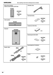
Main and rear speakers (and rear center speaker for NS-P236) NX-230P X 4 X 5 Subwoofer cable Mounting brackets Center speaker NX-C230 X 4 X 5 Subwoofer YST-SW005 SSUUPBEWROWOOFOEFRESRYSSYTSETMEMYSYTSSTW -S0W00505 Fasteners (for NX-C230) X 2 Nonskid pads (for NX-230P) X 2 X 3 Speaker cables [4m] Nonskid pads (for YST-SW005) [15m] X 3 Screws X 2 X 3 X 4 X 5 IV UNPACKING After unpacking, check that the following items are included.
Main and rear speakers (and rear center speaker for NS-P236) NX-230P X 4 X 5 Subwoofer cable Mounting brackets Center speaker NX-C230 X 4 X 5 Subwoofer YST-SW005 SSUUPBEWROWOOFOEFRESRYSSYTSETMEMYSYTSSTW -S0W00505 Fasteners (for NX-C230) X 2 Nonskid pads (for NX-230P) X 2 X 3 Speaker cables [4m] Nonskid pads (for YST-SW005) [15m] X 3 Screws X 2 X 3 X 4 X 5 IV UNPACKING After unpacking, check that the following items are included.
Owner's Manual
Page 5
... the unit apart from the walls, allowing enough spaces above , behind and on the rear panel of this before operating your amplifier to read this YAMAHA NS-P230/NS-P236 Speaker Package. Standby mode If the POWER switch is set to generate a howling sound. English Thank you hear distorted noise (i.e. To prevent fire or electric...
... the unit apart from the walls, allowing enough spaces above , behind and on the rear panel of this before operating your amplifier to read this YAMAHA NS-P230/NS-P236 Speaker Package. Standby mode If the POWER switch is set to generate a howling sound. English Thank you hear distorted noise (i.e. To prevent fire or electric...
Owner's Manual
Page 6
... the terminal which is designed for use 12 Frequency characteristics 13 ADVANCED YAMAHA ACTIVE SERVO TECHNOLOGY (for NS-P236 6 E-2 CONNECTIONS 7 An example of basic connections 7 How to connect speaker cables to the input and output terminals of the speakers 9 Connecting the subwoofer to speaker output terminals of the amplifier 10 USING THE SUBWOOFER (YST-SW005) ... 11...
... the terminal which is designed for use 12 Frequency characteristics 13 ADVANCED YAMAHA ACTIVE SERVO TECHNOLOGY (for NS-P236 6 E-2 CONNECTIONS 7 An example of basic connections 7 How to connect speaker cables to the input and output terminals of the speakers 9 Connecting the subwoofer to speaker output terminals of the amplifier 10 USING THE SUBWOOFER (YST-SW005) ... 11...
Owner's Manual
Page 7
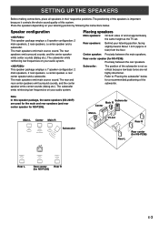
... the whole sound quality of and at approximately the same height as the TV set Rear R Subwoofer Rear L Rear center (for NS-P236) Rear L Rear center Rear R (for NS-P236): Precisely between the main speakers. Refer to "Placing the subwoofer" below . Main L Center Main R Subwoofer Main R Center Main L TV-set . Subwoofer: The position of the...
... the whole sound quality of and at approximately the same height as the TV set Rear R Subwoofer Rear L Rear center (for NS-P236) Rear L Rear center Rear R (for NS-P236): Precisely between the main speakers. Refer to "Placing the subwoofer" below . Main L Center Main R Subwoofer Main R Center Main L TV-set . Subwoofer: The position of the...
Owner's Manual
Page 8
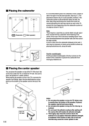
... four corners on the bottom of the subwoofer to the wall. Screen Fastener Peel off the seal as shown in the center of the speaker. If placed, the speaker may die because the sound from the subwoofer when listening in fig. Å. This is placed directly facing the wall, the bass effect... will weaken its adhesive strength. ● Thoroughly wipe clean the surface where the fastener is to fall and cause injury. ● Do not place the speaker on top of a TV if the top is inclined. ● Do not touch the adhesive surface after peeling off the seal E-4 Notes ● Do not...
... four corners on the bottom of the subwoofer to the wall. Screen Fastener Peel off the seal as shown in the center of the speaker. If placed, the speaker may die because the sound from the subwoofer when listening in fig. Å. This is placed directly facing the wall, the bass effect... will weaken its adhesive strength. ● Thoroughly wipe clean the surface where the fastener is to fall and cause injury. ● Do not place the speaker on top of a TV if the top is inclined. ● Do not touch the adhesive surface after peeling off the seal E-4 Notes ● Do not...
Owner's Manual
Page 9
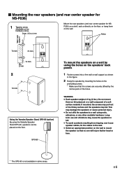
... cause personal injury. ● Do not affix the speakers to 4 mm Mount the rear speakers (and rear center speaker for NS-P236) 1 Tapping screw (Available at the hardware store) Diam. 3.5 to a wall using nails, adhesives, or any other unstable hardware. Do not mount them on the ... mm 70 mm 10 mm Min. 20 mm 2 70 mm Using the Yamaha Speaker Stand SPS-80 (option) By using the Yamaha Speaker Stand SPS-80, speakers can be placed on the wall to fall . English Ⅵ Mounting the rear speakers (and rear center speaker for NSP236) on a shelf, rack or directly on the floor, or...
... cause personal injury. ● Do not affix the speakers to 4 mm Mount the rear speakers (and rear center speaker for NS-P236) 1 Tapping screw (Available at the hardware store) Diam. 3.5 to a wall using nails, adhesives, or any other unstable hardware. Do not mount them on the ... mm 70 mm 10 mm Min. 20 mm 2 70 mm Using the Yamaha Speaker Stand SPS-80 (option) By using the Yamaha Speaker Stand SPS-80, speakers can be placed on the wall to fall . English Ⅵ Mounting the rear speakers (and rear center speaker for NSP236) on a shelf, rack or directly on the floor, or...
Owner's Manual
Page 10
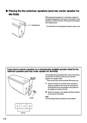
... bracket to the corners on the bottom of the speaker as shown on the bracket. This prevents the speakers from sliding around. * For NS-P236, the nonskid pads include four spare ones. I Placing the the main/rear speakers (and rear center speaker for NS-P236) Nonskid pad When placing the speakers on a flat surface, attach the included nonskid pads...
... bracket to the corners on the bottom of the speaker as shown on the bracket. This prevents the speakers from sliding around. * For NS-P236, the nonskid pads include four spare ones. I Placing the the main/rear speakers (and rear center speaker for NS-P236) Nonskid pad When placing the speakers on a flat surface, attach the included nonskid pads...
Owner's Manual
Page 11
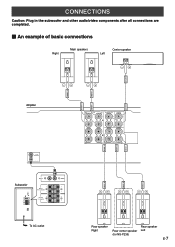
B + + R L R REAR (SURROUND) L REAR R REAR C REAR L REAR R REAR C REAR L Rear speaker Rear speaker Right Rear center speaker Left (for NS-P236) E-7 English CONNECTIONS Caution: Plug in the subwoofer and other audio/video components after all connections are completed. Ⅵ An example of basic connections Right Main speakers Center speaker Left CENTER FRONT L FRONT R FRONT L FRONT R Amplifier SUB WOOFER OUTPUT...
B + + R L R REAR (SURROUND) L REAR R REAR C REAR L REAR R REAR C REAR L Rear speaker Rear speaker Right Rear center speaker Left (for NS-P236) E-7 English CONNECTIONS Caution: Plug in the subwoofer and other audio/video components after all connections are completed. Ⅵ An example of basic connections Right Main speakers Center speaker Left CENTER FRONT L FRONT R FRONT L FRONT R Amplifier SUB WOOFER OUTPUT...
Owner's Manual
Page 12
...(s) of the subwoofer. ● Connect the main, center and rear speakers (and rear center speaker for NS-P236) to the L/MONO INPUT2 terminal. Connect each speaker cord to the corresponding speaker by following the figure on the rear of the DSP amplifier, connect them...speakers only, connect one speaker to reverse the polarity (+, -). If the speaker is connected with the provided speaker cables. * The provided speaker cables have any line output terminal, connect the subwoofer to the speaker output terminals of the amplifier. (Refer to page 9 for details.) * To connect with a YAMAHA...
...(s) of the subwoofer. ● Connect the main, center and rear speakers (and rear center speaker for NS-P236) to the L/MONO INPUT2 terminal. Connect each speaker cord to the corresponding speaker by following the figure on the rear of the DSP amplifier, connect them...speakers only, connect one speaker to reverse the polarity (+, -). If the speaker is connected with the provided speaker cables. * The provided speaker cables have any line output terminal, connect the subwoofer to the speaker output terminals of the amplifier. (Refer to page 9 for details.) * To connect with a YAMAHA...
Owner's Manual
Page 13
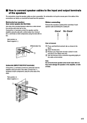
...the amplifier using the side with a white broken line. Connect the (-) terminals on both components using one side of the provided speaker cable has a white broken line and the other side of the cables. Do not bundle or roll up the excess part of...Insert the bare wire. 3 Release your finger from the speakers. Red: positive (+) Black: negative (-) E-9 Subwoofer (INPUT1/OUTPUT terminals) Connect the (+) terminals on both the speaker and the amplifier using the other side has no line. Main/center/rear speakers Rear center speaker (for NS-P236) One side of the cable.
...the amplifier using the side with a white broken line. Connect the (-) terminals on both components using one side of the provided speaker cable has a white broken line and the other side of the cables. Do not bundle or roll up the excess part of...Insert the bare wire. 3 Release your finger from the speakers. Red: positive (+) Black: negative (-) E-9 Subwoofer (INPUT1/OUTPUT terminals) Connect the (+) terminals on both the speaker and the amplifier using the other side has no line. Main/center/rear speakers Rear center speaker (for NS-P236) One side of the cable.
Owner's Manual
Page 14
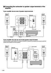
... VOLUME AUTO STANDBY HIGH LOW OFF 0 10 HIGH LOW HIGH CUT INPUT2 /MONO INPUT1 FROM AMPLIFIER OUTPUT TO SPEAKERS POWER ON OFF Left main speaker FRONT R FRONT L (Not included) Speaker output terminals A B To AC outlet Amplifier FRONT R FRONT L (Both A and B speaker outputs must be ON.) If your amplifier has only one set of main...
... VOLUME AUTO STANDBY HIGH LOW OFF 0 10 HIGH LOW HIGH CUT INPUT2 /MONO INPUT1 FROM AMPLIFIER OUTPUT TO SPEAKERS POWER ON OFF Left main speaker FRONT R FRONT L (Not included) Speaker output terminals A B To AC outlet Amplifier FRONT R FRONT L (Both A and B speaker outputs must be ON.) If your amplifier has only one set of main...

Owner's Manual
Page 15
... OFF 3 110V-120V 220V-240V VOLTAGE SELECTOR VOLUME AUTO STANDBY HIGH LOW OFF 0 10 HIGH LOW HIGH CUT INPUT2 /MONO INPUT1 FROM AMPLIFIER OUTPUT TO SPEAKERS POWER ON OFF 220V-240V 110V-120V VOLTAGE SELECTOR 4 5 VOLUME AUTO STANDBY HIGH LOW OFF 0 10 HIGH LOW HIGH CUT 8 9 INPUT2 /MONO... 6 INPUT1 FROM AMPLIFIER 7 OUTPUT TO SPEAKERS 1 Power indicator Lights up GREEN when the POWER switch (2) is pressed in to the ON position and goes off when set to the OFF position...
... OFF 3 110V-120V 220V-240V VOLTAGE SELECTOR VOLUME AUTO STANDBY HIGH LOW OFF 0 10 HIGH LOW HIGH CUT INPUT2 /MONO INPUT1 FROM AMPLIFIER OUTPUT TO SPEAKERS POWER ON OFF 220V-240V 110V-120V VOLTAGE SELECTOR 4 5 VOLUME AUTO STANDBY HIGH LOW OFF 0 10 HIGH LOW HIGH CUT 8 9 INPUT2 /MONO... 6 INPUT1 FROM AMPLIFIER 7 OUTPUT TO SPEAKERS 1 Power indicator Lights up GREEN when the POWER switch (2) is pressed in to the ON position and goes off when set to the OFF position...
Owner's Manual
Page 16
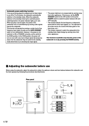
... on (by pressing the POWER switch). Ⅵ Adjusting the subwoofer before use the POWER switch to switch the power between the subwoofer and the main speakers by following the procedures described below 200 Hz of the input signals (i.e., the explosion in red.) When you play a source again, the power of ... subwoofer. Rear panel POWER ON 3 OFF VOLUME AUTO STANDBY HIGH LOW OFF 0 10 HIGH LOW HIGH CUT INPUT2 /MONO INPUT1 FROM AMPLIFIER OUTPUT TO SPEAKERS POWER ON OFF AUTO STANDBY HIGH LOW OFF VOLUME 1, 6 0 10 HIGH LOW HIGH CUT 5 INPUT2 /MONO INPUT1 FROM AMPLIFIER OUTPUT TO...
... on (by pressing the POWER switch). Ⅵ Adjusting the subwoofer before use the POWER switch to switch the power between the subwoofer and the main speakers by following the procedures described below 200 Hz of the input signals (i.e., the explosion in red.) When you play a source again, the power of ... subwoofer. Rear panel POWER ON 3 OFF VOLUME AUTO STANDBY HIGH LOW OFF 0 10 HIGH LOW HIGH CUT INPUT2 /MONO INPUT1 FROM AMPLIFIER OUTPUT TO SPEAKERS POWER ON OFF AUTO STANDBY HIGH LOW OFF VOLUME 1, 6 0 10 HIGH LOW HIGH CUT 5 INPUT2 /MONO INPUT1 FROM AMPLIFIER OUTPUT TO...
Owner's Manual
Page 17
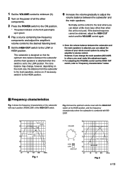
...volume control to the desired listening level. 5 Set the HIGH CUT switch to adjust the volume balance between the subwoofer and the main speakers. Fig. 2 shows the optimum volume level with the HIGH CUT switch at the HIGH position, and the frequency characteristics when the subwoofer...you change , however, depending on the room size, the distance from the subwoofer to the LOW position. The tone balance may change the main speakers (NX-230P) to "Frequency characteristics" below. Ⅵ Frequency characteristics Fig. 1 shows the frequency characteristics of the subwoofer with NX230P. 100 ...
...volume control to the desired listening level. 5 Set the HIGH CUT switch to adjust the volume balance between the subwoofer and the main speakers. Fig. 2 shows the optimum volume level with the HIGH CUT switch at the HIGH position, and the frequency characteristics when the subwoofer...you change , however, depending on the room size, the distance from the subwoofer to the LOW position. The tone balance may change the main speakers (NX-230P) to "Frequency characteristics" below. Ⅵ Frequency characteristics Fig. 1 shows the frequency characteristics of the subwoofer with NX230P. 100 ...
Owner's Manual
Page 18
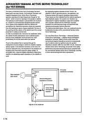
...- adopted Advanced Negative Impedance Converter (ANIC) circuits, which the amplifier supplies special signals. Thus, signals of the speaker unit would become linear with superior damping characteristics. With this new ANIC circuits, Advanced Yamaha Active Servo Technology can , according to generate precise, low-amplitude, lowfrequency waves with respect to accomplish this problem...is a port or opening as waves of great amplitude if the size of the opening and the volume of a new design in a conventionally designed speaker system. ADVANCED YAMAHA ACTIVE SERVO TECHNOLOGY (for...
...- adopted Advanced Negative Impedance Converter (ANIC) circuits, which the amplifier supplies special signals. Thus, signals of the speaker unit would become linear with superior damping characteristics. With this new ANIC circuits, Advanced Yamaha Active Servo Technology can , according to generate precise, low-amplitude, lowfrequency waves with respect to accomplish this problem...is a port or opening as waves of great amplitude if the size of the opening and the volume of a new design in a conventionally designed speaker system. ADVANCED YAMAHA ACTIVE SERVO TECHNOLOGY (for...
Owner's Manual
Page 19
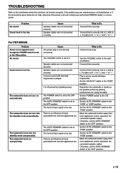
...Set the AUTO STANDBY switch to the "HIGH" position. Move the subwoofer farther away from such appliances and/or reposition the connected speaker cables. The AUTO STANDBY switch is set to the ON position. The level of input signal is set to 0. Set the ...Move the subwoofer farther away from such appliances and/or reposition the connected speaker cables. E-15 English TROUBLESHOOTING Refer to the chart below do not help, disconnect the power cord and contact your authorized YAMAHA dealer or service center. Connect them correctly, that is influenced by placing...
...Set the AUTO STANDBY switch to the "HIGH" position. Move the subwoofer farther away from such appliances and/or reposition the connected speaker cables. The AUTO STANDBY switch is set to the ON position. The level of input signal is set to 0. Set the ...Move the subwoofer farther away from such appliances and/or reposition the connected speaker cables. E-15 English TROUBLESHOOTING Refer to the chart below do not help, disconnect the power cord and contact your authorized YAMAHA dealer or service center. Connect them correctly, that is influenced by placing...
Owner's Manual
Page 20
SPECIFICATIONS Ⅵ NX-230P, NX-C230 Type ......... Full range acoustic-suspension speaker system Magnetic shielding type Driver 5 cm (2") full range cone speaker x 2 Nominal Input Power 30W Maximum Input Power 100W Impedance 6Ω Frequency Response
SPECIFICATIONS Ⅵ NX-230P, NX-C230 Type ......... Full range acoustic-suspension speaker system Magnetic shielding type Driver 5 cm (2") full range cone speaker x 2 Nominal Input Power 30W Maximum Input Power 100W Impedance 6Ω Frequency Response


