
Owner's Manual
Page 1
... it an excellent mixer for BGM or Karaoke and microphone input. The MV800 is divided into two zones, the MV800 also offers individual control of those two zones directly from the front panel without the need to enjoy years of your MV800 and its excellent functions, and to change the wiring making it , in a safe place for purchasing the YAMAHA MV800. MIXER Owner's Manual Thank you...
... it an excellent mixer for BGM or Karaoke and microphone input. The MV800 is divided into two zones, the MV800 also offers individual control of those two zones directly from the front panel without the need to enjoy years of your MV800 and its excellent functions, and to change the wiring making it , in a safe place for purchasing the YAMAHA MV800. MIXER Owner's Manual Thank you...
Owner's Manual
Page 2
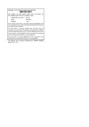
Owner's Manual WARNING: THIS APPARATUS MUST BE EARTHED IMPORTANT THE WIRES IN THIS MAINS LEAD ARE COLOURED IN ACCORDANCE WITH THE FOLLOWING CODE: GREEN-AND-YELLOW : EARTH BLUE : NEUTRAL BROWN : LIVE As the colours of the wires in the mains lead of this apparatus may not correspond with the ... GREEN and YELLOW. MV800 - The wire which is coloured BROWN must be connected to the terminal in your plug, proceed as follows: The wire which is coloured GREEN and YELLOW must be connected to the terminal which is marked by the letter E or by YAMAHA KEMBLE MUSIC (U.K.) LTD. The ...
Owner's Manual WARNING: THIS APPARATUS MUST BE EARTHED IMPORTANT THE WIRES IN THIS MAINS LEAD ARE COLOURED IN ACCORDANCE WITH THE FOLLOWING CODE: GREEN-AND-YELLOW : EARTH BLUE : NEUTRAL BROWN : LIVE As the colours of the wires in the mains lead of this apparatus may not correspond with the ... GREEN and YELLOW. MV800 - The wire which is coloured BROWN must be connected to the terminal in your plug, proceed as follows: The wire which is coloured GREEN and YELLOW must be connected to the terminal which is marked by the letter E or by YAMAHA KEMBLE MUSIC (U.K.) LTD. The ...
Owner's Manual
Page 3
..., or noise, or if a foreign object or liquid gets inside the unit, turn the power switch off immediately. A damaged power cord is a potential electrical shock hazard. Never pull the cord. A damaged power cord is a fire and electrical shock hazard. • Should this unit or allow enough free space around the unit for repair. Using the unit in damage. If you think internal inspection...
..., or noise, or if a foreign object or liquid gets inside the unit, turn the power switch off immediately. A damaged power cord is a potential electrical shock hazard. Never pull the cord. A damaged power cord is a fire and electrical shock hazard. • Should this unit or allow enough free space around the unit for repair. Using the unit in damage. If you think internal inspection...

Owner's Manual
Page 4
... mixer is located on the rear panel of stereo outputs that are also supplied for an emergency announcement system. Contents Front & Rear Panels 3 Front Panel Section 3 Stereo Channel & Master Control Sections 4 Rear Panel Section 6 About the Accessories 8 About the MV800's Functions 9 Applications 10 Supplement 13 Specifications 13 Dimensions 15 Block and Level Diagrams 16 Caution: When the unit is installed in a rack, please use the external power switch on a power distributor, etc. 2 MV800 Features • The MV800 provides 8 channels with monaural input jacks, A/B stereo...
... mixer is located on the rear panel of stereo outputs that are also supplied for an emergency announcement system. Contents Front & Rear Panels 3 Front Panel Section 3 Stereo Channel & Master Control Sections 4 Rear Panel Section 6 About the Accessories 8 About the MV800's Functions 9 Applications 10 Supplement 13 Specifications 13 Dimensions 15 Block and Level Diagrams 16 Caution: When the unit is installed in a rack, please use the external power switch on a power distributor, etc. 2 MV800 Features • The MV800 provides 8 channels with monaural input jacks, A/B stereo...
Owner's Manual
Page 5
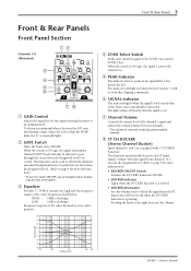
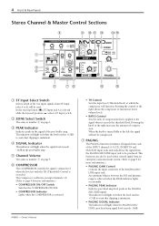
... used to effectively eliminate unwanted background noise (sounds that is smaller than the designated level). (Refer to which the signal from channel 1 or 2 exceeds the designated level. (Refer to page 9 for more information.) • DUCKER ON/OFF Switch Switches the DUCKER Function ON/OFF. • DUCKER Indicator Lights when the DUCKER function is operating. w GATE Switch Turns the Noise Gate ON/OFF. u Channel Volume Controls the output level of control over high and low...
... used to effectively eliminate unwanted background noise (sounds that is smaller than the designated level). (Refer to which the signal from channel 1 or 2 exceeds the designated level. (Refer to page 9 for more information.) • DUCKER ON/OFF Switch Switches the DUCKER Function ON/OFF. • DUCKER Indicator Lights when the DUCKER function is operating. w GATE Switch Turns the Noise Gate ON/OFF. u Channel Volume Controls the output level of control over high and low...
Owner's Manual
Page 6
... volume levels. • RATIO Control Sets the ratio of the INPUT channels (1-8, ST), INSERT IN and STACK IN input jacks and only allows the signal from ST Input jacks A or B, will be produced. 4 Front & Rear Panels Stereo Channel & Master Control Sections y o !0 !1 !3 !4 !5 q w e r t ui !2 !6 q ST Input Select Switch Selects which the compressor will function. w ZONE Select Switch The same as number u on input channels 1-8. (Refer to page 9 for more information.) • COMPRESSOR ON/OFF Switch Switches the COMPRESSOR ON/OFF. • COMPRESSOR Indicator Lights...
... volume levels. • RATIO Control Sets the ratio of the INPUT channels (1-8, ST), INSERT IN and STACK IN input jacks and only allows the signal from ST Input jacks A or B, will be produced. 4 Front & Rear Panels Stereo Channel & Master Control Sections y o !0 !1 !3 !4 !5 q w e r t ui !2 !6 q ST Input Select Switch Selects which the compressor will function. w ZONE Select Switch The same as number u on input channels 1-8. (Refer to page 9 for more information.) • COMPRESSOR ON/OFF Switch Switches the COMPRESSOR ON/OFF. • COMPRESSOR Indicator Lights...
Owner's Manual
Page 7
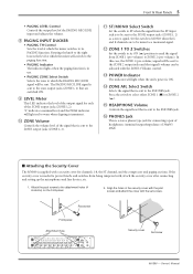
... output jacks (ZONE 1,2). Owner's Manual o LEVEL Meter This LED indicates the level of the output signal for connecting a pair of headphones (nominal output/impedance of the PAGING MIC/LINE input and adjusts the volume. "0" indicates a nominal level, and the PEAK indicator will light when the unit's power is ON. !4 ZONE AFL Select Switch Selects the signal that is sent to the zone output jacks (ZONE 1, 2) that is sent to the ZONE output jacks (ZONE 1, 2). !1 ST/MONO Select Switch Set...
... output jacks (ZONE 1,2). Owner's Manual o LEVEL Meter This LED indicates the level of the output signal for connecting a pair of headphones (nominal output/impedance of the PAGING MIC/LINE input and adjusts the volume. "0" indicates a nominal level, and the PEAK indicator will light when the unit's power is ON. !4 ZONE AFL Select Switch Selects the signal that is sent to the zone output jacks (ZONE 1, 2) that is sent to the ZONE output jacks (ZONE 1, 2). !1 ST/MONO Select Switch Set...
Owner's Manual
Page 8
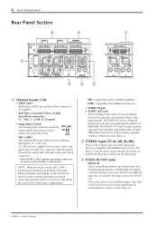
... used to the INPUT jack. • MIC (+48V) This position allows the connection of 0dB/600Ω. to the ZONE 2 bus. These jacks can be used as a reverb, delay, etc. Owner's Manual The INSERT IN jack is a balanced phone type jack with a nominal output/impedance of the transformer is balanced phone type jack with a nominal input/impedance of the input channel. Two devices, A and B, can be no problem connecting balanced dynamic microphones or line level...
... used to the INPUT jack. • MIC (+48V) This position allows the connection of 0dB/600Ω. to the ZONE 2 bus. These jacks can be used as a reverb, delay, etc. Owner's Manual The INSERT IN jack is a balanced phone type jack with a nominal output/impedance of the transformer is balanced phone type jack with a nominal input/impedance of the input channel. Two devices, A and B, can be no problem connecting balanced dynamic microphones or line level...
Owner's Manual
Page 9
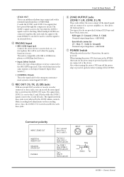
... output/impedance +4dB/600Ω u POWER Switch When the switch is in use. Owner's Manual Also, when turning the power OFF, turn on the recording device. The signal from these jacks. The signal sent from ZONE 1 is sent to the 1L and 1R jacks while the ZONE 2 signal is not affected by the ZONE volume controls. Two types of microphone or device connected to the MIC/LINE input jack. Connector polarity INPUT, ZONE OUT INSERT IN INSERT...
... output/impedance +4dB/600Ω u POWER Switch When the switch is in use. Owner's Manual Also, when turning the power OFF, turn on the recording device. The signal from these jacks. The signal sent from ZONE 1 is sent to the 1L and 1R jacks while the ZONE 2 signal is not affected by the ZONE volume controls. Two types of microphone or device connected to the MIC/LINE input jack. Connector polarity INPUT, ZONE OUT INSERT IN INSERT...
Owner's Manual
Page 10
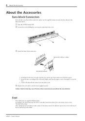
... supplied with a minus (-) driver. Feet Four rubber feet are used without the cover attached. Owner's Manual q Turn the POWER switch OFF. 8 About the Accessories About the Accessories Euro-block Connectors If you decide to open. 2. w Loosen the screws holding the cover in its original location. Insert the wires according to the jack's pole display, and turn the screw on the top of the mixer. Connect...
... supplied with a minus (-) driver. Feet Four rubber feet are used without the cover attached. Owner's Manual q Turn the POWER switch OFF. 8 About the Accessories About the Accessories Euro-block Connectors If you decide to open. 2. w Loosen the screws holding the cover in its original location. Insert the wires according to the jack's pole display, and turn the screw on the top of the mixer. Connect...
Owner's Manual
Page 11
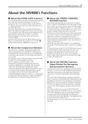
... MIC/LINE Input jack. About the MV800's Functions 9 About the MV800's Functions I About the Compressor Function When someone is talking with the TH (Threshold) control. One way to prevent the problem is used in the event of compression used to set the PAGING MIC/LINE input's gain setting. The volume must be reduced. This function is to turn the microphone off or set with sources connected to hear the speaker over the music. Also, the setting that is also supplied...
... MIC/LINE Input jack. About the MV800's Functions 9 About the MV800's Functions I About the Compressor Function When someone is talking with the TH (Threshold) control. One way to prevent the problem is used in the event of compression used to set the PAGING MIC/LINE input's gain setting. The volume must be reduced. This function is to turn the microphone off or set with sources connected to hear the speaker over the music. Also, the setting that is also supplied...
Owner's Manual
Page 12
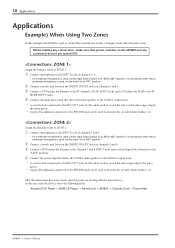
... 2 main speakers to the ZONE 2 output jacks. * A cassette deck connected to the REC OUT jacks 2L/2R can be used , set the switch to the "LINE" position. Assign the Karaoke room to ZONE 1. w Connect a reverb unit between the INSERT IN/OUT jacks on Channels 3 and 4. Owner's Manual 10 Applications Applications Example) When Using Two Zones In this case, turn the power on the MV800 and any connections, make sure that power switches on starting with the input...
... 2 main speakers to the ZONE 2 output jacks. * A cassette deck connected to the REC OUT jacks 2L/2R can be used , set the switch to the "LINE" position. Assign the Karaoke room to ZONE 1. w Connect a reverb unit between the INSERT IN/OUT jacks on Channels 3 and 4. Owner's Manual 10 Applications Applications Example) When Using Two Zones In this case, turn the power on the MV800 and any connections, make sure that power switches on starting with the input...

Owner's Manual
Page 13
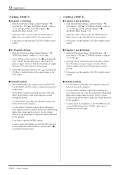
MV800 - ZONE 1 Power Amp + Speakers Microphone for MC Microphone for Speakers CD Player for BGM DVD Player for Karaoke Microphone for Karaoke Applications 11 ZONE 2 Power Amp + Speakers Microphone for Karaoke DVD Player for recording ZONE 2 * If necessary, setup the compressor or paging functions. Owner's Manual Set the 1 TO 2 Switch OFF Set the ZONE 1 switch to "ON" on CH 5-8 only Reverb Unit PHONES REC OUT 1L, 1R Cassette Deck for recording ZONE 1 REC OUT 2L, 2R Cassette Deck...
MV800 - ZONE 1 Power Amp + Speakers Microphone for MC Microphone for Speakers CD Player for BGM DVD Player for Karaoke Microphone for Karaoke Applications 11 ZONE 2 Power Amp + Speakers Microphone for Karaoke DVD Player for recording ZONE 2 * If necessary, setup the compressor or paging functions. Owner's Manual Set the 1 TO 2 Switch OFF Set the ZONE 1 switch to "ON" on CH 5-8 only Reverb Unit PHONES REC OUT 1L, 1R Cassette Deck for recording ZONE 1 REC OUT 2L, 2R Cassette Deck...
Owner's Manual
Page 14
Channel Volume = ), ZONE Select Switch = only set "1" to ON (>), ZONE 1's ZONE Volume = Make the following settings. 12 Applications G Channel 1-4 Settings 1.
Channel Volume = ), ZONE Select Switch = only set "1" to ON (>), ZONE 1's ZONE Volume = Make the following settings. 12 Applications G Channel 1-4 Settings 1.
Owner's Manual
Page 15
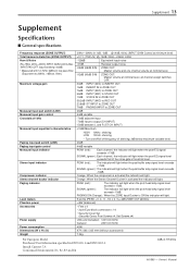
... OUTPUT) Total harmonic distortion (ZONE OUTPUT) Hum & Noise (Rs=150Ω, 20Hz-20kHz, INPUT GAIN Control=Max., INPUT PAD=OFF, Input Sensitivity=-60dB) * Measured with 12.7kHz, 6dB/oct. filter.) Maximum voltage gain Monaural input pad switch (LINE) Monaural input gain control Crosstalk at 1kHz Monaural input equalizer's characteristics Paging input pad switch (LINE) Paging input gain control Monaural input indicator Stereo input indicator Compressor indicator Stereo channel ducker indicator Paging indicator Level meters Phantom power Accessories Power supply Power consumption Dimensions...
... OUTPUT) Total harmonic distortion (ZONE OUTPUT) Hum & Noise (Rs=150Ω, 20Hz-20kHz, INPUT GAIN Control=Max., INPUT PAD=OFF, Input Sensitivity=-60dB) * Measured with 12.7kHz, 6dB/oct. filter.) Maximum voltage gain Monaural input pad switch (LINE) Monaural input gain control Crosstalk at 1kHz Monaural input equalizer's characteristics Paging input pad switch (LINE) Paging input gain control Monaural input indicator Stereo input indicator Compressor indicator Stereo channel ducker indicator Paging indicator Level meters Phantom power Accessories Power supply Power consumption Dimensions...
Owner's Manual
Page 16
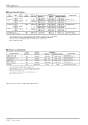
... (3.16V) RCA phono jack *4 30mW 75mW Stereo phone jack (TRS) *5 Specifications are subject to maximum gain. *2 XLR type connector, Euro-block connector, phone jack (TRS) (T=Hot, R=Cold, S=Gnd): balanced type. *3 RCA phono jack, phone jack (TRS) (T=ZONE 1, R= ZONE 2, S=Gnd): unbalanced type. • 0dB=0.775Vrms, 0dBV=1Vrms I Input Specifications Input connectors PAD GAIN Control MIC CH INPUT (1-8) LINE MIC LINE ST INPUT [L, R] (A, B) MAX MIN PAGING MIC LINE MIC LINE MAX MIN CH INSERT IN (1-8) STACK IN...
... (3.16V) RCA phono jack *4 30mW 75mW Stereo phone jack (TRS) *5 Specifications are subject to maximum gain. *2 XLR type connector, Euro-block connector, phone jack (TRS) (T=Hot, R=Cold, S=Gnd): balanced type. *3 RCA phono jack, phone jack (TRS) (T=ZONE 1, R= ZONE 2, S=Gnd): unbalanced type. • 0dB=0.775Vrms, 0dBV=1Vrms I Input Specifications Input connectors PAD GAIN Control MIC CH INPUT (1-8) LINE MIC LINE ST INPUT [L, R] (A, B) MAX MIN PAGING MIC LINE MIC LINE MAX MIN CH INSERT IN (1-8) STACK IN...
Owner's Manual
Page 18
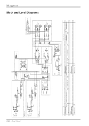
... ZONE2 [0dB] ZONE1 ZONE2 STACK IN [0dB] CV GEN. G +30dB +20dB +10dB CH INPUT GAIN:MIN PAD:LINE[+10dB] 0dB -10dB -20dB -30dB CH INPUT GAIN:MIN PAD:MIC[-16dB] CH INPUT GAIN:MAX PAD:LINE[-34dB] -40dB -50dB -60dB CH INPUT GAIN:MAX PAD:MIC[-60dB] Max. Owner's Manual CH INPUT (CH1) MIC [-60~-16dB] LINE + [-34~+10dB] - G +L G ZONE2 OUT [+4dB] +R - ZONE1 ZONE2 16 Supplement Block and Level Diagrams MV800 -
... ZONE2 [0dB] ZONE1 ZONE2 STACK IN [0dB] CV GEN. G +30dB +20dB +10dB CH INPUT GAIN:MIN PAD:LINE[+10dB] 0dB -10dB -20dB -30dB CH INPUT GAIN:MIN PAD:MIC[-16dB] CH INPUT GAIN:MAX PAD:LINE[-34dB] -40dB -50dB -60dB CH INPUT GAIN:MAX PAD:MIC[-60dB] Max. Owner's Manual CH INPUT (CH1) MIC [-60~-16dB] LINE + [-34~+10dB] - G +L G ZONE2 OUT [+4dB] +R - ZONE1 ZONE2 16 Supplement Block and Level Diagrams MV800 -


