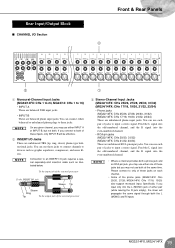
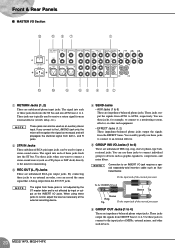
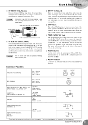
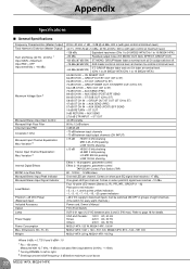
MG32/14FX MG24/14FX Owners Manual
Page 2
..., heat registers, stoves, or other . WARNING TO REDUCE THE RISK OF FIRE OR ELECTRIC SHOCK, DO NOT EXPOSE THIS APPARATUS TO RAIN OR MOISTURE. 2 MG32/14FX, MG24/14FX The exclamation point within the product's enclosure that produce heat. 9 Do not defeat the safety purpose of important operating and maintenance (servicing) instructions in any...
MG32/14FX MG24/14FX Owners Manual
Page 3
... holes during electrical storms. • When removing the electric plug from the outlet, and have the idevice inspected by qualified Yamaha service personnel. • If this device should be malfunctioning, discontinue use the device or headphones for a long period of time at ..., place heavy objects on it, or place it in a position where anyone could walk on the buttons, switches or connectors. 3 MG32/14FX, MG24/14FX These precautions include, but are located on it . Improper grounding can cause permanent hearing loss. CAUTION Always follow the basic precautions listed...
MG32/14FX MG24/14FX Owners Manual
Page 4
... distributed by the safety earth symbol or coloured GREEN or GREEN-and-YELLOW. Utilize power outlets that is marked by the letter E or by Yamaha-Kemble Music (U.K.) Ltd. (3 wires). 4 MG32/14FX, MG24/14FX XLR-type connectors are wired as indicated in the instructions contained in this manual, meets FCC requirements. Consult qualified...
MG32/14FX MG24/14FX Owners Manual
Page 6
... are equipped with an INSERT I/O jack for independent connection to any combination of monaural channels. Features ● Provides 24 (MG32/14FX) or 16 (MG24/14FX) monaural input channels suitable for connection to both vocal and instrumental inputs. ● Convenient "tap delay" feature lets you ...power supply can use , so that you for your purchase of the YAMAHA MG32/14FX or MG24/14FX mixing console. Also provides four line-level stereo inputs. ● Built-in dual digital effector, based on Yamaha's acclaimed SPX multi-effector technology, can also serve as an auxiliary stereo...
MG32/14FX MG24/14FX Owners Manual
Page 7
... connec- Introduction Connecting to Power (1) Be sure that the mixer's power switch is off ( ). (2) Connect the socket end of the power cord to prevent overheating. 7 MG32/14FX, MG24/14FX
MG32/14FX MG24/14FX Owners Manual
Page 8
Master Control Block 3 STEREO/MONO Section (p. 13) 4 GROUP Section (p. 14) 5 SEND Section (p. 14) 6 RETURN Section (p. 15) 7 INTERNAL DIGITAL EFFECTS Section (p. 16) 8 METER/PHONES Section (p. 17) 9 2TR INPUT Section (p. 17) 10 TALKBACK Section (p. 18) 11 LAMP Jack (p. 18) 8 MG32/14FX, MG24/14FX Front Panel Front & Rear Panels 7 65 11 8 9 10 8 1 Channel Control Block 1 MONAURAL CHANNELS Section (p. 10) 2 STEREO CHANNELS Section (p. 10) 2 4 3 Note: Within this manual, all panel illustrations show the MG32/14FX panel.
MG32/14FX MG24/14FX Owners Manual
Page 9
Rear Panel Front & Rear Panels 13 Rear Input/Output Block 12 CHANNEL I/O Section (p. 19) 13 MASTER I/O Section (p. 20) 12 Note: Within this manual, all panel illustrations show the MG32/14FX panel. 9 MG32/14FX, MG24/14FX
MG32/14FX MG24/14FX Owners Manual
Page 10
Front & Rear Panels Channel Control Block ■ MONAURAL CHANNELS Section STEREO CHANNELS Section Monaural Channels 1 to 24 (MG32/14FX) 1 to 16 (MG24/14FX) Stereo Channels 25/26 to 31/32 (MG32/14FX) 17/18 to 23/24 (MG24/14FX) G 1 2 3 4 5 6 5 7 8 9 0 A B C D E F 1 PAD Switch When this switch is on ( ), the GAIN control ...Boost HIGH Shelving 10 kHz HI-MID LO-MID Peaking Peaking 3 kHz 800 Hz ±15 dB LOW Shelving 100 Hz 10 MG32/14FX, MG24/14FX On monaural channels: When the PAD switch (1) is off . Turning the knob to the right boosts the corresponding frequency band,...
MG32/14FX MG24/14FX Owners Manual
Page 11
... turn on or off ( ). NOTE • The ON switch does not affect the operation of the Stereo bus. To turn all the way down. 11 MG32/14FX, MG24/14FX D GROUP Switches Use these buses is on , press the switch in ( ) so that you cut off . • To reduce noise, turn PFL feed on...
MG32/14FX MG24/14FX Owners Manual
Page 12
..., set of these switches: for CHs 1 to 8, for CHs 9 to 16, and for CHs 17 to 24. Stereo channels 12 MG32/14FX, MG24/14FX The MG32/14FX has three of eight adjacent channels. The MG24/14FX has two: for CHs 9 to16. But note that the switch may result if you do not need phantom power. Monaural...
MG32/14FX MG24/14FX Owners Manual
Page 13
... 20). 4 MONO Fader Adjusts the level of the signal that feeds from the ST bus into the MONO output jack (0 on page 20). 13 MG32/14FX, MG24/14FX NOTE This control has no effect on page 20). Front & Rear Panels Master Control Block ■ STEREO/MONO Section You use this LPF off. If...
MG32/14FX MG24/14FX Owners Manual
Page 14
... the corresponding TO ST switch (2) is always fed into the corresponding GROUP OUT jack (see page 11) to the corresponding internal digital effect. 14 MG32/14FX, MG24/14FX While the signal from the GROUP bus into the ST bus, after first passing the signal through the GROUP fader (4) and the PAN control...
MG32/14FX MG24/14FX Owners Manual
Page 15
... the level of the signal from the RETURN 1 and RETURN 2 jacks (see page 20). To turn the PFL feed on, press the switch in ( ). 15 MG32/14FX, MG24/14FX If you can monitor the signal at the PHONES jack.
MG32/14FX MG24/14FX Owners Manual
Page 16
.... 2 PARAMETER Controls This knob sets the parameter value for the corresponding internal digital effect. These parameter values are retained even after power goes off . 16 MG32/14FX, MG24/14FX To set the delay time for internal EFFECT 2 by tapping on the button. The indicator next to the button flashes in ( ). The top...
MG32/14FX MG24/14FX Owners Manual
Page 17
... GROUP switch is on . 2 STEREO Level Meters If the GROUP switch (4) is on, the left and right meters show the level to 4, in ( ). 17 MG32/14FX, MG24/14FX The "0" position corresponds to the standard level. The PEAK indicator comes on both the PFL and AFL buses, the PHONES jack will indicate only the...
MG32/14FX MG24/14FX Owners Manual
Page 18
... connected to this switch is on ( ), the mixer feeds the signal from the MIC jack into AUX buses 1 to 4. 4 ST Switch If this jack. 18 MG32/14FX, MG24/14FX NOTE This jack does not supply phantom power. 2 Talkback Control Adjusts the talkback level. 3 AUX1-4 Switch If this switch is not connected.
MG32/14FX MG24/14FX Owners Manual
Page 19
...-numbered channel. Feed the L signal into the odd-numbered channel, and the R signal into the even-numbered channel. • RCA-pin jacks (MG32/14FX: CHs 29/30, 31/32) (MG24/14FX: CHs 21/22, 23/24) These are unbalanced TRS (tip, ring, sleeve) phone-type bidirectional jacks. NOTE • Where a channel provides... you input only into the L (MONO) jack of jacks to both . You can use each channel. • Some of the phone jacks (MG32/14FX: CHs 25/26, 27/28; MG24/14FX: CHs 17/18, 19/20) also support monaural input. Specifically, if you may use both the L (MONO) and R inputs....
MG32/14FX MG24/14FX Owners Manual
Page 20
... signal as a CD player or DAT deck) directly to the mixer for example, to connect to a monitoring system, effector, or other such devices. 20 MG32/14FX, MG24/14FX You use these jacks feeds into the ST bus and into the ST bus. The signal into each of these jacks to connect to an...
MG32/14FX MG24/14FX Owners Manual
Page 21
... (+) Pin 3: Ground INPUT INPUT B, GROUP OUT, AUX SEND (1 to 6), EFFECT SEND (1, 2), ST SUB OUT* INSERT I/O, GROUP INS I/O, ST INSERT I /O jack requires a special separately-sold ) YAMAHA FC5 foot switch to this jack and then set internal EFFECT 2 to [16] TAP DELAY, you use the foot switch (as to an external mixer...use with the mixer. B POWER Switch Use this output is controlled by the MONO fader in the Master Control block (see page 13). MG32/14FX, MG24/14FX 21 The level for this output is for connection to set the power on the signals from the ST bus. NOTE The ST master ...
MG32/14FX MG24/14FX Owners Manual
Page 22
Appendix Specifications ■ General Specifications Frequency Characteristics (Master Output) Total Harmonic Distortion (Master Output) Hum and Noise (20 Hz - 20 kHz) 1 Input GAIN = Maximum Input PAD = OFF Input sensitivity = -60 dBu Maximum Voltage Gain 2 Monaural/Stereo Input Gain Control Monaural High Pass Filter Channel Input PAD Crosstalk (1 kHz) Monaural Input Channel Equalization: Max. Variation 3 Stereo Input Channel Equalization: Max. Dimensions (W × H × D) Weight 20 Hz-20 kHz +1 dB, -3 dB @+4 dBu, 600 Ω (with gain control at minimum level) Variation 3 ...