Yamaha GF24 Support and Manuals
Get Help and Manuals for this Yamaha item

Yamaha GF24 Videos

MESA YAMAHA GF24
Duration: 5:58
Total Views: 54
Duration: 5:58
Total Views: 54
Yamaha mixer repair(GF24/12) old mixer. Camotes adventure
Duration: 6:36
Total Views: 297
Duration: 6:36
Total Views: 297
Yamaha GF24/12 Mesa de Som MIXER
Duration: :03
Total Views: 4,401
Duration: :03
Total Views: 4,401
Mesa Profissional Yamaha Gf24/12
Duration: :38
Total Views: 702
Duration: :38
Total Views: 702
Popular Yamaha GF24 Manual Pages
GF24/12 GF16/12 GF12/12 Owners Manual - Page 4
...17
Specifications 21
General specifications 21 Input specifications 22 Output specifications 22 Dimensions 23 Block/Level Diagram 24
-Owner's Manual Since...for purchasing the Yamaha GF24/12, GF16/12, or GF12/12 mixing console. These mixers provide an ample ..., this manual carefully. This can be sent to enjoy years of trouble-free performance, please read this mixer provides six...
GF24/12 GF16/12 GF12/12 Owners Manual - Page 5
...and rear panel
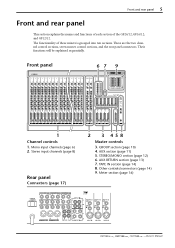
This section explains the names and functions of each section of these mixers is grouped into ten sections. Front panel
67 9
1
2
3
4
5
...4dBV
R
L
STEREO OUT +4dBV
R L 24R
22R
REC OUT -10dBV
INPUT A
INPUT A
INPUT A
INPUT A
-Owner's Manual Other controls/connectors (page 14) 9. TAPE IN section (page 14) 8. Stereo input channels (page 8)
Rear panel
Connectors (page...
GF24/12 GF16/12 GF12/12 Owners Manual - Page 6

..., and sends the result to the AUX buses 1-6. When a knob is in .
4 PEAK indicator This is "nominal".
-Owner's Manual The input channel section processes the signal from the input jacks of the GF24/12 {GF16/12, GF12/12}. The center frequency and equalizer type for the high pass filter that detects...
GF24/12 GF16/12 GF12/12 Owners Manual - Page 7
... 5 AUX 6
GROUP
AUX PFL/AFL ST
1234 123456 LR LR
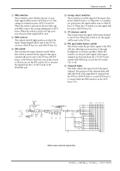
Mono input channel signal flow
-Owner's Manual However even if this switch is turned off .
When this switch is off, you to the corresponding pair of AUX... 1-4, and AUX buses 1- 6 (except when the PRE switch is on for AUX buses 3-6). This setting is switched in ) the signal will be sent to the ST bus, GROUP buses, or AUX buses...
GF24/12 GF16/12 GF12/12 Owners Manual - Page 8

.../12} jacks (6 and 0 of the connector section) are the two stereo input channels provided by the GF24/12, GF16/12, and GF12/12. It will be accommodated is near the clipping level. The center ...and 15/16 on the GF16, and 9/10 and 11/12 on when the switch is pressed in the "w" position.
-Owner's Manual 8 Front and rear panel
4 6
A B GAIN
+10
-34
80
PEAK HIGH
-15
+15
MID
-15
+15
LOW...
GF24/12 GF16/12 GF12/12 Owners Manual - Page 9
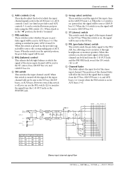
This setting is switched in the upward position, the post-fader signal will be sent.
8 BAL (balance) control This adjusts the left/right ...-fader signal to the PFL/ AFL bus, allowing you can be sent to GROUP bus 1/2. When this switch is off . GF12/12 GF16/12 GF24/12
*1 9L
13L
21L
*2 10R
14R
22R
*3 11L
15L
23L
*4 12R
16R
24R
GAIN LOW MID HIGH
PEAK ST
ON
BAL
1-2
GROUP
...
GF24/12 GF16/12 GF12/12 Owners Manual - Page 11

.... AUX 123456
AUX OUT 1
AFL AUX OUT 2
AFL
AUX OUT 3-4: AUX OUT 5-6:
Same as AUX OUT 1-2
PFL/AFL LR
AUX section signal flow
-Owner's Manual Master controls 11
1 2
10
10
10
10
10
10
5
5
5
5
5
5
0
0
0
0
0
0
5
5
5
5
5
5
10
10
10
10
10
10
15
15
15
15
15
15
20
20
20
20...
GF24/12 GF16/12 GF12/12 Owners Manual - Page 12
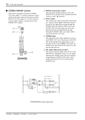
...
PFL/AFL LR
L STEREO OUT R
AFL POST MONO
MONO OUT
STEREO/MONO section signal flow
-Owner's Manual
The position of the STEREO fader will affect the signals that are the main output of the mixer, and the MONO OUT jack (page 17, 2 in , the signal after -fader listen) switch This switch...
GF24/12 GF16/12 GF12/12 Owners Manual - Page 13
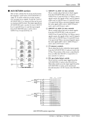
... 1 AUX 2 ST
PFL
GROUP 3 GROUP 4
AUX 3 AUX 4 ST
PFL
GROUP
AUX
ST PFL/AFL
1234 123456 LR LR
AUX RETURN section signal flow
-Owner's Manual
GF24/12 GF16/12 GF12/12 Owners Manual - Page 14
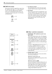
...AFL GROUP
TAPE IN
2 3
0
10
C-R MONITOR
LEVEL
0
10
PHONES
LEVEL
4 5
PHONES
6
-Owner's Manual
s Other controls/connectors
1 PHANTOM +48 V (phantom power supply) switch This is on, the PHANTOM indicator (page...bus or the TAPE IN jacks (page 17, 4 in the connector section), depending on the setting of the TAPE IN switch (3). Caution: When phantom power is on, connecting an unbalanced device...
GF24/12 GF16/12 GF12/12 Owners Manual - Page 15
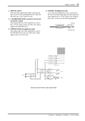
... not affect the output signal of the C-R OUT jacks.
6 PHONES (headphone) jack A set of the signal that is sent to the C-R OUT jacks. The wiring of the signal... MONITOR LEVEL BA
BA
PHONES LEVEL BA
L C-R OUT
R
PHONES
Tape input and monitor output signal flow
-Owner's Manual It does not affect the output signal of the PHONES jack.
5 PHONES LEVEL (headphone) jack This adjusts the level of...
GF24/12 GF16/12 GF12/12 Owners Manual - Page 16
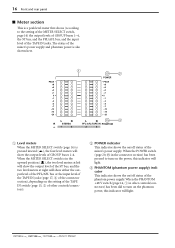
...supply) indicator This indicator shows the on the setting of the TAPE IN switch (page 15, 3 of other controls/connectors) has been slid to the setting of the METER SELECT switch, page 14) ...POWER indicator This indicator shows the on the power, this indicator will light.
-Owner's Manual The status of the mixer's power supply and phantom power is pressed inward ( ), the four level meters will ...
GF24/12 GF16/12 GF12/12 Owners Manual - Page 17
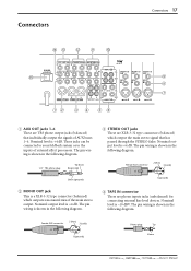
... are XLR-3-32 type connectors (balanced) which outputs a monaural mix of external effect processors. Female XLR connector
2 (hot) 3 (cold)
1 (ground)
Phono plug
Tip
Sleeve
-Owner's Manual Nominal level is +4 dB. Connectors
Connectors 17
E
DC B A
0
POWER ON/ OFF
C-R OUT +4dB ST INSERT I/O 0dB AUX RETURN +4dB
R
LR
L 2L (MONO) 1L
INSERT I/O OUT...
GF24/12 GF16/12 GF12/12 Owners Manual - Page 20
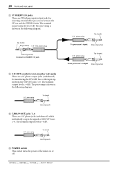
... following diagram.
1/4" phone plug
Tip (send)
Sleeve (ground)
D GROUP OUT jacks 1-4 These are 1/4" phone jacks (unbalanced) which individually output the signals of the mixer on or off.
-Owner's Manual
1/4" phone plug
Tip (send)
To processor's input Sleeve (ground)
1/4" phone plug
Tip (return)
From processor's output Sleeve (ground) The pin wiring is shown...
GF24/12 GF16/12 GF12/12 Owners Manual - Page 22
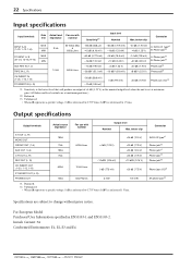
...Manual Unbalanced.
• When dB represents a specific voltage, 0 dB is referenced to 0.775 Vrms, 0 dBV is set... at maximum gain. (All faders and level controls are subject to 1 Vrms.
Output specifications
Output terminals
Actual source impedance
For use with nominal
Output level
Nominal
Max. For European Model.... †2. 22 Specifications
Input specifications...
Yamaha GF24 Reviews
We have not received any reviews for Yamaha yet.