
Owner's Manual
Page 2
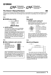
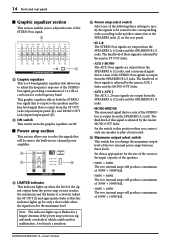
... is +11dB (LIMITER indicator lights), the internal amplifier will deliver 100W into 4Ω. 1 EMX5000-20/EMX5000-12 Reduce the output level at the ` ST OUT jack (input/output panel 0). Use only Neutrik NL4FC plugs for purchasing the Yamaha EMX5000-20/EMX5000-12 Powered Mixer. Neutrik NL4FC CHANNEL B 1+ B+ 1- B- Check the output signal level via the internal...
... is +11dB (LIMITER indicator lights), the internal amplifier will deliver 100W into 4Ω. 1 EMX5000-20/EMX5000-12 Reduce the output level at the ` ST OUT jack (input/output panel 0). Use only Neutrik NL4FC plugs for purchasing the Yamaha EMX5000-20/EMX5000-12 Powered Mixer. Neutrik NL4FC CHANNEL B 1+ B+ 1- B- Check the output signal level via the internal...
Owner's Manual
Page 3
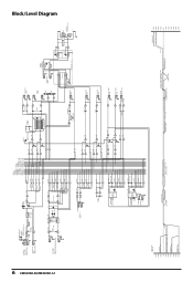
...R 63Hz 125Hz 250Hz 500Hz 1kHz 2kHz 4kHz 8kHz 16kHz Block/Level Diagram 6 EMX5000-20/EMX5000-12 CH INPUT A [-60~-16dB] [-34~+10dB] EMX5000-12:CH1-8 EMX5000-20:CH1-16 B CH INSERT I/O [0dB] EMX5000-12:CH1-8 EMX5000-20:CH1-16 +48V PHANTOM 8CH/SW EMX5000-12:[CH1-8] EMX5000-20:[CH1-8] [CH9-16] PAD HA [0dB] 26dB GAIN [-60~-16dB] ...) L ST SUB OUT [+4dB] R L ST OUT [+4dB] R PEAK DR PEAK DR MONO OUT [+4dB] A POWER AMP IN [+4dB] B YAMAHA SPEAKER PROCESSING YSP YSP MAIN L AUX1 AUX1 MONO BRIDGE INV Signal Select MAIN R MONO AUX2 MONO BRIDGE POWER AMP Controls LIMITTER 500W 300W 100W PA...
...R 63Hz 125Hz 250Hz 500Hz 1kHz 2kHz 4kHz 8kHz 16kHz Block/Level Diagram 6 EMX5000-20/EMX5000-12 CH INPUT A [-60~-16dB] [-34~+10dB] EMX5000-12:CH1-8 EMX5000-20:CH1-16 B CH INSERT I/O [0dB] EMX5000-12:CH1-8 EMX5000-20:CH1-16 +48V PHANTOM 8CH/SW EMX5000-12:[CH1-8] EMX5000-20:[CH1-8] [CH9-16] PAD HA [0dB] 26dB GAIN [-60~-16dB] ...) L ST SUB OUT [+4dB] R L ST OUT [+4dB] R PEAK DR PEAK DR MONO OUT [+4dB] A POWER AMP IN [+4dB] B YAMAHA SPEAKER PROCESSING YSP YSP MAIN L AUX1 AUX1 MONO BRIDGE INV Signal Select MAIN R MONO AUX2 MONO BRIDGE POWER AMP Controls LIMITTER 500W 300W 100W PA...
Owner's Manual
Page 5
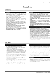
... the power switch of the unit as soon as marked on a power cord covered by a carpet. • Use only the included power cord for a replacement. EMX5000-20/EMX5000-12-Owner's Manual A damaged power cord is a potential fire hazard. A damaged power cord is a fire hazard. • If you know you continue using...
... the power switch of the unit as soon as marked on a power cord covered by a carpet. • Use only the included power cord for a replacement. EMX5000-20/EMX5000-12-Owner's Manual A damaged power cord is a potential fire hazard. A damaged power cord is a fire hazard. • If you know you continue using...
Owner's Manual
Page 6
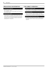
... this unit may induce noise. FOR CORRECT OPERATION - If noise occurs, use the telephone away from the unit. If noise occurs, relocate the affected equipment. EMX5000-20/EMX5000-12-Owner's Manual Interference with moving contacts, such switches, rotary controls, faders, and connectors, deteriorates over time. Connector pin assignments • XLR-type connectors are...
... this unit may induce noise. FOR CORRECT OPERATION - If noise occurs, use the telephone away from the unit. If noise occurs, relocate the affected equipment. EMX5000-20/EMX5000-12-Owner's Manual Interference with moving contacts, such switches, rotary controls, faders, and connectors, deteriorates over time. Connector pin assignments • XLR-type connectors are...
Owner's Manual
Page 7
... excessive input levels. • A maximum output select switch lets you easily adjust the delay time. • The EMX5000-20/EMX5000-12 has implemented "EEEngine", Yamaha's epochal amp drive technology to vocals or instruments. You can be used to add reverb or ambience to create an... specifications 31 Dimensions 32 Installing an optional rack mount kit 32 Block/Level Diagram 33 EMX5000-20/EMX5000-12-Owner's Manual You can be selected as appropriate for purchasing the Yamaha EMX5000-20/EMX5000-12 Powered Mixer. In order to the speaker output jacks, two stereo output channels ...
... excessive input levels. • A maximum output select switch lets you easily adjust the delay time. • The EMX5000-20/EMX5000-12 has implemented "EEEngine", Yamaha's epochal amp drive technology to vocals or instruments. You can be used to add reverb or ambience to create an... specifications 31 Dimensions 32 Installing an optional rack mount kit 32 Block/Level Diagram 33 EMX5000-20/EMX5000-12-Owner's Manual You can be selected as appropriate for purchasing the Yamaha EMX5000-20/EMX5000-12 Powered Mixer. In order to the speaker output jacks, two stereo output channels ...
Owner's Manual
Page 8
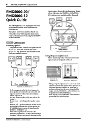
... (one main speaker each speaker to the SPEAKERS A jack and to ST L-R. Never connect the speakers in stereo. 6 EMX5000-20/EMX5000-12 Quick Guide EMX5000-20/ EMX5000-12 Quick Guide The following this case, use a cable designed for speaker connection. • Speakers with a Speakon connector can...Connecting speakers Using speaker cables, connect each to use the SPEAKERS 1 jacks to output the signal from the EMX5000-20/EMX5000-12. • When connecting a Speakon connector to the EMX5000-20/EMX5000-12, be sure to turn the plug to the right to the ST L-R position as shown here, ...
... (one main speaker each speaker to the SPEAKERS A jack and to ST L-R. Never connect the speakers in stereo. 6 EMX5000-20/EMX5000-12 Quick Guide EMX5000-20/ EMX5000-12 Quick Guide The following this case, use a cable designed for speaker connection. • Speakers with a Speakon connector can...Connecting speakers Using speaker cables, connect each to use the SPEAKERS 1 jacks to output the signal from the EMX5000-20/EMX5000-12. • When connecting a Speakon connector to the EMX5000-20/EMX5000-12, be sure to turn the plug to the right to the ST L-R position as shown here, ...
Owner's Manual
Page 9
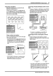
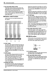
...of the corresponding device for the same channel at once (EMX5000-20: 1-8 and 9- 16, EMX5000-12: 1-8), so mics other than condenser mics must be connected to all channel inputs at the same time. EMX5000-20 (EMX5000-12) Microphone EMX5000-20 (EMX5000-12) Using a condenser microphone Turn on the PHANTOM switch...not connect or disconnect a condenser microphone while the power to the unit is turned off to the REC OUT jacks. EMX5000-20/EMX5000-12-Owner's Manual EMX5000-20/EMX5000-12 Quick Guide 7 Connecting a microphone Make sure that the power is on and the PHANTOM switch has been turned...
...of the corresponding device for the same channel at once (EMX5000-20: 1-8 and 9- 16, EMX5000-12: 1-8), so mics other than condenser mics must be connected to all channel inputs at the same time. EMX5000-20 (EMX5000-12) Microphone EMX5000-20 (EMX5000-12) Using a condenser microphone Turn on the PHANTOM switch...not connect or disconnect a condenser microphone while the power to the unit is turned off to the REC OUT jacks. EMX5000-20/EMX5000-12-Owner's Manual EMX5000-20/EMX5000-12 Quick Guide 7 Connecting a microphone Make sure that the power is on and the PHANTOM switch has been turned...
Owner's Manual
Page 10
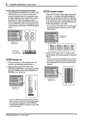
... external devices connected to the EMX5000-20/EMX5000-12. 2 Make sure that the ST OUT fader of the EMX5000-20/EMX5000-12 is lowered, and then press the POWER switch of the EMX5000-20/ EMX5000-12 to turn on the YAMAHA SPEAKER PROCESSING switch in stereo. 8 EMX5000-20/EMX5000-12 Quick Guide Connecting an electronic musical instrument To the EMX5000-20/EMX5000-12's LINE or ST...
... external devices connected to the EMX5000-20/EMX5000-12. 2 Make sure that the ST OUT fader of the EMX5000-20/EMX5000-12 is lowered, and then press the POWER switch of the EMX5000-20/ EMX5000-12 to turn on the YAMAHA SPEAKER PROCESSING switch in stereo. 8 EMX5000-20/EMX5000-12 Quick Guide Connecting an electronic musical instrument To the EMX5000-20/EMX5000-12's LINE or ST...
Owner's Manual
Page 11
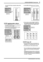
... speakers. 3 Set the EFFECT RTN fader to the "0" position. 3 EMX5000-20 (EMX5000-12) EMX5000-20 (EMX5000-12) STEP 4 Applying built-in the EFFECT section. The ON switch indicator lights up. 1 EMX5000-20 (EMX5000-12) 2 4 If you want to use the EMX5000-20/EMX5000-12, we recommend that you want to apply the effect. EMX5000-20/EMX5000-12 Quick Guide 9 Use the ST OUT fader to...
... speakers. 3 Set the EFFECT RTN fader to the "0" position. 3 EMX5000-20 (EMX5000-12) EMX5000-20 (EMX5000-12) STEP 4 Applying built-in the EFFECT section. The ON switch indicator lights up. 1 EMX5000-20 (EMX5000-12) 2 4 If you want to use the EMX5000-20/EMX5000-12, we recommend that you want to apply the effect. EMX5000-20/EMX5000-12 Quick Guide 9 Use the ST OUT fader to...
Owner's Manual
Page 12
... are as follows: HIGH: 10kHz, ±15 dB, shelving type MID: 250Hz-5kHz, ±15 dB, peaking type LOW: 100Hz, ±15 dB, shelving type EMX5000-20/EMX5000-12-Owner's Manual The high-pass filter is on /off switch for the input signal of each channel. For the mid range, use the...
... are as follows: HIGH: 10kHz, ±15 dB, shelving type MID: 250Hz-5kHz, ±15 dB, peaking type LOW: 100Hz, ±15 dB, shelving type EMX5000-20/EMX5000-12-Owner's Manual The high-pass filter is on /off switch for the input signal of each channel. For the mid range, use the...
Owner's Manual
Page 13
...the ON switch S in the center when the knob is positioned at "w," at right at R, and at left at L. 8 BAL (balance) control (EMX5000-20: Channels 17/18-19/20, EMX5000-12: Channels 9/10-11/12) The BAL knobs set the stereo position of the signal that is turned on. 0 PEAK indicator The indicator...can be sent to the AUX1 and 2 buses. D s Stereo sub input section In this switch is sent to the PHONES jack (input/output panel D). EMX5000-20/EMX5000-12-Owner's Manual The signal will send a signal from which this section, you wish to use the headphones to the STEREO bus. Note: The amount...
...the ON switch S in the center when the knob is positioned at "w," at right at R, and at left at L. 8 BAL (balance) control (EMX5000-20: Channels 17/18-19/20, EMX5000-12: Channels 9/10-11/12) The BAL knobs set the stereo position of the signal that is turned on. 0 PEAK indicator The indicator...can be sent to the AUX1 and 2 buses. D s Stereo sub input section In this switch is sent to the PHONES jack (input/output panel D). EMX5000-20/EMX5000-12-Owner's Manual The signal will send a signal from which this section, you wish to use the headphones to the STEREO bus. Note: The amount...
Owner's Manual
Page 14
... A 1/2 jacks to the MONO OUT jack (input/output panel C). s 2TR IN section In this section, you wish to the 2TR IN jacks (input/output panel 5). EMX5000-20/EMX5000-12-Owner's Manual s Master control section In this section, you to adjust the level of the outputs. If the Power amp select switch Y is set...
... A 1/2 jacks to the MONO OUT jack (input/output panel C). s 2TR IN section In this section, you wish to the 2TR IN jacks (input/output panel 5). EMX5000-20/EMX5000-12-Owner's Manual s Master control section In this section, you to adjust the level of the outputs. If the Power amp select switch Y is set...
Owner's Manual
Page 15
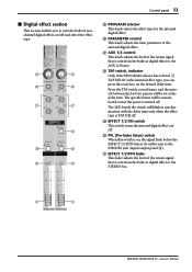
.... Q AUX 1/2 control This knob adjusts the level of the internal digital effect. O O P P Q Q R S S T T O PROGRAM selector This knob selects the effect type for the internal digital effect. U U EMX5000-20/EMX5000-12-Owner's Manual Control panel 13 s Digital effect section This section enables you can press this switch is on / off . P PARAMETER control This knob adjusts...
.... Q AUX 1/2 control This knob adjusts the level of the internal digital effect. O O P P Q Q R S S T T O PROGRAM selector This knob selects the effect type for the internal digital effect. U U EMX5000-20/EMX5000-12-Owner's Manual Control panel 13 s Digital effect section This section enables you can press this switch is on / off . P PARAMETER control This knob adjusts...
Owner's Manual
Page 16
... that is a mix of the STEREO bus signals is output from the ST OUT jacks (input/output panel 0), and MONO OUT jack (input/output panel C). EMX5000-20/EMX5000-12-Owner's Manual The final level of this as appropriate for only a short while when the signal reaches the maximum level. 14 Front and...
... that is a mix of the STEREO bus signals is output from the ST OUT jacks (input/output panel 0), and MONO OUT jack (input/output panel C). EMX5000-20/EMX5000-12-Owner's Manual The final level of this as appropriate for only a short while when the signal reaches the maximum level. 14 Front and...
Owner's Manual
Page 17
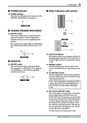
...set this switch is on. ] a b c ^ Peak level indicator This indicator allows you to on . [ s Other indicators and controls ` s YAMAHA SPEAKER PROCESSING \ ON/OFF switch This switch enables you to the ST SUB OUT jacks (input/output panel A). To adjust the frequency, use a slotted ...depending on the speakers. Control panel 15 s POWER indicator [ POWER indicator This indicator will light up when the output level reaches +4 dB. EMX5000-20/EMX5000-12-Owner's Manual c LPF control, ON/OFF switch This switch applies a low-pass filter to the signal that are using a ...
...set this switch is on. ] a b c ^ Peak level indicator This indicator allows you to on . [ s Other indicators and controls ` s YAMAHA SPEAKER PROCESSING \ ON/OFF switch This switch enables you to the ST SUB OUT jacks (input/output panel A). To adjust the frequency, use a slotted ...depending on the speakers. Control panel 15 s POWER indicator [ POWER indicator This indicator will light up when the output level reaches +4 dB. EMX5000-20/EMX5000-12-Owner's Manual c LPF control, ON/OFF switch This switch applies a low-pass filter to the signal that are using a ...
Owner's Manual
Page 18
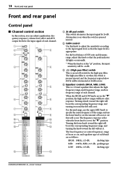
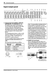
... other than condenser microphones must be connected to the INPUT B input jacks of channels or channel 17/18-19/20 (EMX5000-20), 9/10-11/ 12 (EMX5000-12) input jacks if the PHANTOM +48V switch (control panel 3) is not possible to a wide range of the external ... and rhythm machines). 16 Front and rear panel Input/output panel 1 3 4 56 8 0 A E F G 2 1 Channel input jacks (INPUT A, INPUT B) EMX5000-20: 1-16, EMX5000-12: 1-8 By using the GAIN control (control panel 2) you can provide +48V phantom power, allowing you to insert an external effect processor, such as appropriate...
... other than condenser microphones must be connected to the INPUT B input jacks of channels or channel 17/18-19/20 (EMX5000-20), 9/10-11/ 12 (EMX5000-12) input jacks if the PHANTOM +48V switch (control panel 3) is not possible to a wide range of the external ... and rhythm machines). 16 Front and rear panel Input/output panel 1 3 4 56 8 0 A E F G 2 1 Channel input jacks (INPUT A, INPUT B) EMX5000-20: 1-16, EMX5000-12: 1-8 By using the GAIN control (control panel 2) you can provide +48V phantom power, allowing you to insert an external effect processor, such as appropriate...
Owner's Manual
Page 19
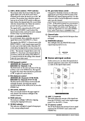
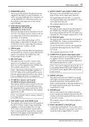
... 1 bus, AUX 2 bus, and STEREO bus. The signal adjusted by the EFF 1, 2 control of each channel will light. 4 LINE (stereo) input jacks EMX5000-20: 17/18-19/20, EMX5000-12: 9/10-11/12 These are the input jacks for the type of electronic instruments, cassette decks, or CD players. A ST SUB OUT jacks...0 ST OUT jacks These phone jacks output the line level signal of the STEREO bus. EMX5000-20/EMX5000-12-Owner's Manual You can use your foot to the STEREO bus. E FOOT SW EFFECT 2 ON/OFF jack A separately sold Yamaha FC5 foot switch can be added to switch the built-in digital EFFECT 2 on , the...
... 1 bus, AUX 2 bus, and STEREO bus. The signal adjusted by the EFF 1, 2 control of each channel will light. 4 LINE (stereo) input jacks EMX5000-20: 17/18-19/20, EMX5000-12: 9/10-11/12 These are the input jacks for the type of electronic instruments, cassette decks, or CD players. A ST SUB OUT jacks...0 ST OUT jacks These phone jacks output the line level signal of the STEREO bus. EMX5000-20/EMX5000-12-Owner's Manual You can use your foot to the STEREO bus. E FOOT SW EFFECT 2 ON/OFF jack A separately sold Yamaha FC5 foot switch can be added to switch the built-in digital EFFECT 2 on , the...
Owner's Manual
Page 20
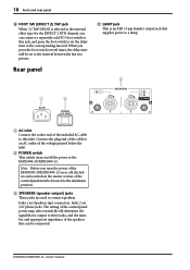
... jack This is an XLR (3-pin female) output jack that can connect a separately sold FC5 foot switch to this inlet. Jacks 2 are Speakon-type connectors. EMX5000-20/EMX5000-12-Owner's Manual 18 Front and rear panel F FOOT SW (EFFECT 2) TAP jack When TAP DELAY is selected as the internal effect type for the... to this jack, and press the foot switch to set to the interval between the last two presses. When you turn the power of the EMX5000-20/EMX5000-12 on /off , the faders and controls in the master section of the voltage printed below the inlet. 2 POWER switch This switch turns on ...
... jack This is an XLR (3-pin female) output jack that can connect a separately sold FC5 foot switch to this inlet. Jacks 2 are Speakon-type connectors. EMX5000-20/EMX5000-12-Owner's Manual 18 Front and rear panel F FOOT SW (EFFECT 2) TAP jack When TAP DELAY is selected as the internal effect type for the... to this jack, and press the foot switch to set to the interval between the last two presses. When you turn the power of the EMX5000-20/EMX5000-12 on /off , the faders and controls in the master section of the voltage printed below the inlet. 2 POWER switch This switch turns on ...
Owner's Manual
Page 21
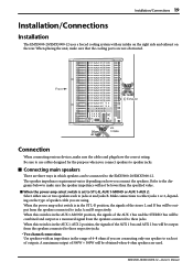
... from the speakers connected to these jacks. Be sure to use cables designed for the purpose when you connect the speakers. EMX5000-20/EMX5000-12-Owner's Manual When placing the unit, make sure that the cooling ports are not obstructed. Installation/Connections 19 Installation/Connections Installation The... EMX5000-20/EMX5000-12 uses a forced cooling system with an impedance in the range of 4-8 ohms if you are connecting only one or two...
... from the speakers connected to these jacks. Be sure to use cables designed for the purpose when you connect the speakers. EMX5000-20/EMX5000-12-Owner's Manual When placing the unit, make sure that the cooling ports are not obstructed. Installation/Connections 19 Installation/Connections Installation The... EMX5000-20/EMX5000-12 uses a forced cooling system with an impedance in the range of 4-8 ohms if you are connecting only one or two...
Owner's Manual
Page 22
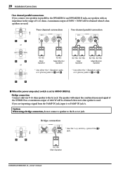
... the 1+(+) and 2+(-) pins of the STEREO bus. The speaker will output the combined monaural signal of the 1 jack. 8Ω-16Ω Main Speaker EMX5000-20/EMX5000-12-Owner's Manual 20 Installation/Connections • Two channel parallel connections If you are used . A maximum output of and . Two-channel connection Two-channel parallel connection or 4Ω...
... the 1+(+) and 2+(-) pins of the STEREO bus. The speaker will output the combined monaural signal of the 1 jack. 8Ω-16Ω Main Speaker EMX5000-20/EMX5000-12-Owner's Manual 20 Installation/Connections • Two channel parallel connections If you are used . A maximum output of and . Two-channel connection Two-channel parallel connection or 4Ω...
