
AVC-50 OWNERS MANUAL
Page 1
... ., Rear Panel -Farts and Their Functions. -87 ' System Poisibilities System Connection Diagram 10 Connections 11 Power Cords 11 Speakers 11 Audio Components 11 Video Components 13 Remote Control Cables 15 Basic Operations 15 Listening to a Sound Source 15 Recording a Sound Source 15 Watching a Video Source 15 Recording a Video Source 15 GL, Viewirq, DFluepcl°iacaiuting Using the Surround Sound Processor Rear Speaker Placement Remote Control Unit Battery Installation Controls Using the Remote Control Adding a Graphic Equalizer Specifications Troubleshooting tt...
... ., Rear Panel -Farts and Their Functions. -87 ' System Poisibilities System Connection Diagram 10 Connections 11 Power Cords 11 Speakers 11 Audio Components 11 Video Components 13 Remote Control Cables 15 Basic Operations 15 Listening to a Sound Source 15 Recording a Sound Source 15 Watching a Video Source 15 Recording a Video Source 15 GL, Viewirq, DFluepcl°iacaiuting Using the Surround Sound Processor Rear Speaker Placement Remote Control Unit Battery Installation Controls Using the Remote Control Adding a Graphic Equalizer Specifications Troubleshooting tt...
AVC-50 OWNERS MANUAL
Page 6
... a rear speaker pair in a 4-speaker system. sharpen edges and contours). CO PICTURE SELECTOR This seesaw type button is used to vary the audio signal delay time, from the audio signal. VCR 2 INPUT Jacks These jacks are effective only when the AVC-50 is most effective with video sources. DELAY TIME-This rotary control is used to select the video source you wish to monitor (Video Cassette Recorder 2, Video Cassette Recorder 1, Video Disc Player, Television Tuner, Tape Deck 2, Tape Deck 1, Auxiliary, Tuner, Compact Disc Player, or Turntable). lJ REMOTE CONTROL Sensor...
... a rear speaker pair in a 4-speaker system. sharpen edges and contours). CO PICTURE SELECTOR This seesaw type button is used to vary the audio signal delay time, from the audio signal. VCR 2 INPUT Jacks These jacks are effective only when the AVC-50 is most effective with video sources. DELAY TIME-This rotary control is used to select the video source you wish to monitor (Video Cassette Recorder 2, Video Cassette Recorder 1, Video Disc Player, Television Tuner, Tape Deck 2, Tape Deck 1, Auxiliary, Tuner, Compact Disc Player, or Turntable). lJ REMOTE CONTROL Sensor...
AVC-50 OWNERS MANUAL
Page 7
... L and R channels are used for polarity, so insert plugs correctly. 7 VCR 2-Connect a second video cassette recorder here for both recording and playback. (4) OUTPUT Terminals These terminals allow a number of how these to connect the audio signal cables from your components to the proper input/output jacks for each component. REAR PANEL PARTS AND THEIR FUNCTiONS. jai 1,ic041W'0. PHONO-Connect to the two unswitched outlets is controlled by the remote control power switch. VDP-Connect a video disc player here. VCR 2-Connect a second video recorder...
... L and R channels are used for polarity, so insert plugs correctly. 7 VCR 2-Connect a second video cassette recorder here for both recording and playback. (4) OUTPUT Terminals These terminals allow a number of how these to connect the audio signal cables from your components to the proper input/output jacks for each component. REAR PANEL PARTS AND THEIR FUNCTiONS. jai 1,ic041W'0. PHONO-Connect to the two unswitched outlets is controlled by the remote control power switch. VDP-Connect a video disc player here. VCR 2-Connect a second video recorder...
AVC-50 OWNERS MANUAL
Page 8
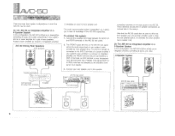
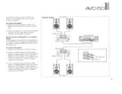
... AVC-50 functions strictly as an integrated amplifier, controlling all audio and video 2-Speaker System 0 AVC-50 rear panel ..n le" 4NeGJt.44, f_i_°$ritgaZilen41240"iii/: Front terminals I oteiDitirwo.- That signal (TAPE IN or AUX) must then be connected to a TAPE IN terminal, an AUX terminal, or any component input terminal other than PHONO) Amplifier • is the recommended system configuration, as outlined later in this system: 1. If your system, and as a power amplifier...
... AVC-50 functions strictly as an integrated amplifier, controlling all audio and video 2-Speaker System 0 AVC-50 rear panel ..n le" 4NeGJt.44, f_i_°$ritgaZilen41240"iii/: Front terminals I oteiDitirwo.- That signal (TAPE IN or AUX) must then be connected to a TAPE IN terminal, an AUX terminal, or any component input terminal other than PHONO) Amplifier • is the recommended system configuration, as outlined later in this system: 1. If your system, and as a power amplifier...
AVC-50 OWNERS MANUAL
Page 9
... the TAPE IN, AUX, or other input terminals on the OUTPUT section of speaker& The surround sound processing modes will not function in a 4-speaker system. Connect the speakers to Rear Amp. Front .3pea,cer'S • 4-)1; To connect this system: 1. Follow standard connection procedures as Preamplifier in a 4-Speaker System It is also possible to drive the front speaker pair. Connect the FRONT terminal to the power amplifier (receiver or integrated amplifier) set up to use the AVC-50...
... the TAPE IN, AUX, or other input terminals on the OUTPUT section of speaker& The surround sound processing modes will not function in a 4-speaker system. Connect the speakers to Rear Amp. Front .3pea,cer'S • 4-)1; To connect this system: 1. Follow standard connection procedures as Preamplifier in a 4-Speaker System It is also possible to drive the front speaker pair. Connect the FRONT terminal to the power amplifier (receiver or integrated amplifier) set up to use the AVC-50...
AVC-50 OWNERS MANUAL
Page 10
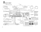
... AVC-50 power switch Use this outlet for swi-.j...9 tape deck with • CD Player mark Il Tuner . a 0 • • • •••o Tape Deck 2 • Super Woofer (With Amplifier) Speakers • • Speakers 10 terminal TV tuner Video output terminal Audio output terminal Remote terminal for other than PHONO j Power plugs for turntable with: ,,!T• j mat = ANA vac.° Turntable FAITir,T] OUTPUT CD player with ,SAMmark LINE OUT o •.•O Tapir Deck 1 LINE IN Video input terminal ,,, Audio input...
... AVC-50 power switch Use this outlet for swi-.j...9 tape deck with • CD Player mark Il Tuner . a 0 • • • •••o Tape Deck 2 • Super Woofer (With Amplifier) Speakers • • Speakers 10 terminal TV tuner Video output terminal Audio output terminal Remote terminal for other than PHONO j Power plugs for turntable with: ,,!T• j mat = ANA vac.° Turntable FAITir,T] OUTPUT CD player with ,SAMmark LINE OUT o •.•O Tapir Deck 1 LINE IN Video input terminal ,,, Audio input...
AVC-50 OWNERS MANUAL
Page 11
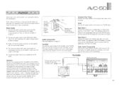
...-50 rear panel speaker terminals Red is , that all cables are observed. Compact Disc Player Connect the output cables of another audio tape unit to the TAPE 1 jacks. Other Audio Components Connect the output cables of the compact disc player to the AUX jacks. Remote cable with mini-plug specially for use with turntables with the input/output cables. 4. Power Cords 1. markings are well away from the speakers. TUrntable Connect the output cables of the tuner to the GND terminal. Tuner Connect the output cables of the turntable to the PHONO jacks, and connect the ground wire...
...-50 rear panel speaker terminals Red is , that all cables are observed. Compact Disc Player Connect the output cables of another audio tape unit to the TAPE 1 jacks. Other Audio Components Connect the output cables of the compact disc player to the AUX jacks. Remote cable with mini-plug specially for use with turntables with the input/output cables. 4. Power Cords 1. markings are well away from the speakers. TUrntable Connect the output cables of the tuner to the GND terminal. Tuner Connect the output cables of the turntable to the PHONO jacks, and connect the ground wire...
AVC-50 OWNERS MANUAL
Page 13
... a TV tuner to Amp Stereo-sMono Cable STEREO Mono Cable This cable has 3 plugs at one end: two stereo and one mono. Connect the audio output cables from a TV tuner to the TV audio jacks: Video Disc Player Connect the video output cable from a video disc player to the VDP jack. Super Woofer _ fr-AT ',H 13 TV Tuner TV Tuner Audio output terminal Video output terminal y. Video output terminal Stereo plugs Mono Plug To. Connect the audio output cables from a video disc player to the VDP audio jacks. Connect the end with two plugs to the power amplifier. 7 Super Woofer Input...
... a TV tuner to Amp Stereo-sMono Cable STEREO Mono Cable This cable has 3 plugs at one end: two stereo and one mono. Connect the audio output cables from a TV tuner to the TV audio jacks: Video Disc Player Connect the video output cable from a video disc player to the VDP jack. Super Woofer _ fr-AT ',H 13 TV Tuner TV Tuner Audio output terminal Video output terminal y. Video output terminal Stereo plugs Mono Plug To. Connect the audio output cables from a video disc player to the VDP audio jacks. Connect the end with two plugs to the power amplifier. 7 Super Woofer Input...

AVC-50 OWNERS MANUAL
Page 14
... the VCR 1 jacks. Connect the audio output cables from a video cassette recorder to the REC OUT jacks. TV Monitor 2 Connect the video cable from a second monitor to the rear panel VCR 2 terminals is connected here, any component connected to the MONITOR OUT 2 jack. Note that the audio connections to the monitor are not necessary as a camera, to your speakers through the amplifier. AVC-50 TV Monitor 1 Connect the video cable from a monitor to your speakers through the amplifier. Note that when a component is defeated.
... the VCR 1 jacks. Connect the audio output cables from a video cassette recorder to the REC OUT jacks. TV Monitor 2 Connect the video cable from a second monitor to the rear panel VCR 2 terminals is connected here, any component connected to the MONITOR OUT 2 jack. Note that the audio connections to the monitor are not necessary as a camera, to your speakers through the amplifier. AVC-50 TV Monitor 1 Connect the video cable from a monitor to your speakers through the amplifier. Note that when a component is defeated.
AVC-50 OWNERS MANUAL
Page 15
... other Processing Mode controls, see the section, "Using the Video Enhancer" Note that all connected components. Use the INPUT BALANCE control to further adjust the relative volume of the button to select the components as indicated on the panel, in succession. Press the left or right direction. Note that since audio and video selection are completely independent, you to turn the equipment on your amplifier, press the POWER switch to control the components from the components to...
... other Processing Mode controls, see the section, "Using the Video Enhancer" Note that all connected components. Use the INPUT BALANCE control to further adjust the relative volume of the button to select the components as indicated on the panel, in succession. Press the left or right direction. Note that since audio and video selection are completely independent, you to turn the equipment on your amplifier, press the POWER switch to control the components from the components to...

AVC-50 OWNERS MANUAL
Page 16
... television tuner, use the Video Enhancer to obtain a high-quality source image. When viewing a video tape recording, use the Video Enhancer to retain most .of adjustment is Video Level, Sharpness, and then Detail. If this switch is pressed during playback. This control has no effect on the video source signal being monitored. Make sure all of objects and people should increase in sharpness as you turn the control clockwise...
... television tuner, use the Video Enhancer to obtain a high-quality source image. When viewing a video tape recording, use the Video Enhancer to retain most .of adjustment is Video Level, Sharpness, and then Detail. If this switch is pressed during playback. This control has no effect on the video source signal being monitored. Make sure all of objects and people should increase in sharpness as you turn the control clockwise...

AVC-50 OWNERS MANUAL
Page 17
... test. Turn the DETAIL control clockwise to obtain tie best clarity of sharpness, if necessary, and to add a small amount of detail and texture without false outlines or excessive snow. Turn the SHARPNESS control clockwise to obtain the best edges and contours without coarseness or excessive snow. If you view a video tape recording, use the Video Enhancer every time you adjust the Detail setting...
... test. Turn the DETAIL control clockwise to obtain tie best clarity of sharpness, if necessary, and to add a small amount of detail and texture without false outlines or excessive snow. Turn the SHARPNESS control clockwise to obtain the best edges and contours without coarseness or excessive snow. If you view a video tape recording, use the Video Enhancer every time you adjust the Detail setting...

AVC-50 OWNERS MANUAL
Page 18
... effect will be achieved if the sub-speakers are three modes for musical sources, rather than videos. A small pair of the surround modes. AVC-50 !IlkliSIND THE OHHOLIND SOUND PROCESSOR The AVC-50 incorporates a sophisticated. multi-mode surround sound processing amplifier which the walls are board or concrete if the speakers are also included. The surround sound processor in the AVC-50 is effective only when the AVC-50 is used in a live concert hall, where...
... effect will be achieved if the sub-speakers are three modes for musical sources, rather than videos. A small pair of the surround modes. AVC-50 !IlkliSIND THE OHHOLIND SOUND PROCESSOR The AVC-50 incorporates a sophisticated. multi-mode surround sound processing amplifier which the walls are board or concrete if the speakers are also included. The surround sound processor in the AVC-50 is effective only when the AVC-50 is used in a live concert hall, where...
AVC-50 OWNERS MANUAL
Page 19
... commercially available video cassettes and video discs as video and TV programs. It creates a surround sound effect, and employs a delay circuit for viewing stereo video SWUM Hall Surround This is another exclusive Yamaha circuit which is an exclusive Yamaha surround sound processing mode which effectively turns monaural audio sources in the sound track conies at you from the front speakers, sound effects, background noise, and other ambient noise in natural sounding simulated stereo. AVC-50 II 19...
... commercially available video cassettes and video discs as video and TV programs. It creates a surround sound effect, and employs a delay circuit for viewing stereo video SWUM Hall Surround This is another exclusive Yamaha circuit which is an exclusive Yamaha surround sound processing mode which effectively turns monaural audio sources in the sound track conies at you from the front speakers, sound effects, background noise, and other ambient noise in natural sounding simulated stereo. AVC-50 II 19...

AVC-50 OWNERS MANUAL
Page 20
... output as from the rear speakers DELAY i0-40esite . FR Dolby surround decoder reverberation components are divided between left and right speakers by a comb filter between the left . $, RR high to enjoy a surround effect with TVs or VCRs. • i 1 DELAY DOLBY i0-30nne ' L FL f -o• RL t--,- I -1 R ,S;.•, r)p. -1,-,.-:,c,,,,3sng ioules .WW1. RL 1-. RR ... R NATURAL SURROUND L tV +1Iti la i R When replaying mono sources in a naturally expansive sound with...
... output as from the rear speakers DELAY i0-40esite . FR Dolby surround decoder reverberation components are divided between left and right speakers by a comb filter between the left . $, RR high to enjoy a surround effect with TVs or VCRs. • i 1 DELAY DOLBY i0-30nne ' L FL f -o• RL t--,- I -1 R ,S;.•, r)p. -1,-,.-:,c,,,,3sng ioules .WW1. RL 1-. RR ... R NATURAL SURROUND L tV +1Iti la i R When replaying mono sources in a naturally expansive sound with...

AVC-50 OWNERS MANUAL
Page 21
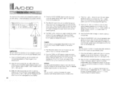
... deck connected to your AVC-50 are Yamaha 1 POWER This button is designed to turn the entire system on which components are compatible with the AVC-50 remote control. Please consult your AVC-50 amplifier Controls is used to control all the most commonly used features of the amplifier. components designed for remote control compatibility (components with your Yamaha dealer for to select the video source you wish component. I ~] fEi VCR 2 IaIBJ5®TV et, 'UPC. Be sure that this remote control 2 INPUT Source...
... deck connected to your AVC-50 are Yamaha 1 POWER This button is designed to turn the entire system on which components are compatible with the AVC-50 remote control. Please consult your AVC-50 amplifier Controls is used to control all the most commonly used features of the amplifier. components designed for remote control compatibility (components with your Yamaha dealer for to select the video source you wish component. I ~] fEi VCR 2 IaIBJ5®TV et, 'UPC. Be sure that this remote control 2 INPUT Source...
AVC-50 OWNERS MANUAL
Page 22
... INPUT source selector buttons, such as turn the amplifier and connected equipment on the remote control. 1. Press it again to the beginning of the tape in decks A and B of your remote control. 1. Press the N> and button moves the tape in a reverse direction. 3. TAPE You can select the preset station frequencies of your remote control. 1. Pressing this button alternates between beginning play and stopping play with the TAPE buttons on the remote control. The VOWME buttons are used to control the over-all output volume...
... INPUT source selector buttons, such as turn the amplifier and connected equipment on the remote control. 1. Press it again to the beginning of the tape in decks A and B of your remote control. 1. Press the N> and button moves the tape in a reverse direction. 3. TAPE You can select the preset station frequencies of your remote control. 1. Pressing this button alternates between beginning play and stopping play with the TAPE buttons on the remote control. The VOWME buttons are used to control the over-all output volume...

AVC-50 OWNERS MANUAL
Page 23
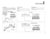
... the power amplifier driving the front speakers (with the PLAY button to the AVC-50 when the AVC-50 is released, the deck will enter the Rec Pause mode. Connect MAIN IN terminals to INPUT terminals on graphic equalizer. tOUALIZER 4. Connect FRONT terminals to OUTPUT terminals on graphic equalizer 3. Press the STOP button to pause while recording. 7. Press the REC/PAUSE button to stop playing a cassette tape 6. AVC-50 driving front speakers, and REAR terminals connected...
... the power amplifier driving the front speakers (with the PLAY button to the AVC-50 when the AVC-50 is released, the deck will enter the Rec Pause mode. Connect MAIN IN terminals to INPUT terminals on graphic equalizer. tOUALIZER 4. Connect FRONT terminals to OUTPUT terminals on graphic equalizer 3. Press the STOP button to pause while recording. 7. Press the REC/PAUSE button to stop playing a cassette tape 6. AVC-50 driving front speakers, and REAR terminals connected...

AVC-50 OWNERS MANUAL
Page 24
.... .A1C-50 1 SPFIFK",OTIGNS AUDIO SECTION Minimum RMS Output Power per Channel 8 ohms, 20 Hz to 20 kHz, 0.05% THD 6 ohms, 20 Hz to 20 kHz, 0.05% THD Dynamic Power per Channel (IHF 8 ohms) (IHF, 6 ohms) (IHF, 4 ohms) Dynamic Headroom 8 ohms Damping Factor (8 ohms 1 kHz) Input Sensitivity/impedance Phono MM AUX/TAPEfTUNER MAIN IN Input Sensitivity (New IHF) Phono MM AUX/TAPE/TUNER Maximum Input Level (1 kHz) Phono MM Output Levellimpedance REC OUT PRE OUT Maximum Voltage Output (20...
.... .A1C-50 1 SPFIFK",OTIGNS AUDIO SECTION Minimum RMS Output Power per Channel 8 ohms, 20 Hz to 20 kHz, 0.05% THD 6 ohms, 20 Hz to 20 kHz, 0.05% THD Dynamic Power per Channel (IHF 8 ohms) (IHF, 6 ohms) (IHF, 4 ohms) Dynamic Headroom 8 ohms Damping Factor (8 ohms 1 kHz) Input Sensitivity/impedance Phono MM AUX/TAPEfTUNER MAIN IN Input Sensitivity (New IHF) Phono MM AUX/TAPE/TUNER Maximum Input Level (1 kHz) Phono MM Output Levellimpedance REC OUT PRE OUT Maximum Voltage Output (20...
AVC-50 OWNERS MANUAL
Page 25
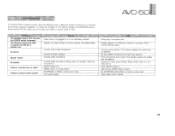
... plugged in . Turn video unit on . Set SHARPNESS AND DETAIL controls to operate the AVC-50 or another unit. Wrong video unit selected. Ill : '':i 4; Set the amplifier controls to turn on when the POWER switch is not completely inserted. Firmly connect the audio plugs. Video unit not turned on . Firmly connect Remote cables. Press ON/OFF Switch in or is pressed. Incorrect amplifier operation. PE,REC Switch in the SYMPTOM column, disconnect the AVC-50's power cord and contact your dealer or service center...
... plugged in . Turn video unit on . Set SHARPNESS AND DETAIL controls to operate the AVC-50 or another unit. Wrong video unit selected. Ill : '':i 4; Set the amplifier controls to turn on when the POWER switch is not completely inserted. Firmly connect the audio plugs. Video unit not turned on . Firmly connect Remote cables. Press ON/OFF Switch in or is pressed. Incorrect amplifier operation. PE,REC Switch in the SYMPTOM column, disconnect the AVC-50's power cord and contact your dealer or service center...


