Quick Reference Guide
Page 7
... imaging drum installed 43 Imaging drum up/down error 43 Fan error 44 Fuser unit error 44 Other problems 45 The printer continuously displays "Booting" or "Initializing." 45 False "No toner cartridge installed" message 45 False "No fuser unit installed" message 45 Right-side door indicated being open when it is closed... print is wrinkled 57 Macintosh printing problems 58 Image never prints 58 Image is rotated 90 degrees 58 Image prints in black-and-white 58 Printer isn't in the Chooser 59 Windows printing problems 59 Image never prints 59 vi Phaser 2135 Color Printer
... imaging drum installed 43 Imaging drum up/down error 43 Fan error 44 Fuser unit error 44 Other problems 45 The printer continuously displays "Booting" or "Initializing." 45 False "No toner cartridge installed" message 45 False "No fuser unit installed" message 45 Right-side door indicated being open when it is closed... print is wrinkled 57 Macintosh printing problems 58 Image never prints 58 Image is rotated 90 degrees 58 Image prints in black-and-white 58 Printer isn't in the Chooser 59 Windows printing problems 59 Image never prints 59 vi Phaser 2135 Color Printer

Quick Reference Guide
Page 9
Electronic boards 105 System controller board 105 RAM DIMMs 106 Hard drive 107 Print engine controller board 108 Toner sensor board 109 Entrance sensor board 111 High voltage power supply 112 Low voltage power supply 114 Control panel 115 Paper feed components 116 Tray 1 ... handle (front) 132 Fuser latching handle (rear) 134 Fuser exit roller 135 Exit sensor assembly 137 Eject guide assembly 138 Stack full sensor 139 viii Phaser 2135 Color Printer
Electronic boards 105 System controller board 105 RAM DIMMs 106 Hard drive 107 Print engine controller board 108 Toner sensor board 109 Entrance sensor board 111 High voltage power supply 112 Low voltage power supply 114 Control panel 115 Paper feed components 116 Tray 1 ... handle (front) 132 Fuser latching handle (rear) 134 Fuser exit roller 135 Exit sensor assembly 137 Eject guide assembly 138 Stack full sensor 139 viii Phaser 2135 Color Printer

Quick Reference Guide
Page 10
Drive assembly components 141 Main motor assembly 141 Imaging drum motor 142 Fuser motor and transfer belt drive motor assembly 143 Xerographic components 144 Shutter plate 144 Color registration sensor assembly 145 Color registration solenoid 146 LED assembly 147 Drum contact assembly 148 Toner sensor actuators 149 Duplex unit 151 FRU List 153 Using the parts list 153 Test Prints 173 Wiring Diagram 177 Service Guide ix
Drive assembly components 141 Main motor assembly 141 Imaging drum motor 142 Fuser motor and transfer belt drive motor assembly 143 Xerographic components 144 Shutter plate 144 Color registration sensor assembly 145 Color registration solenoid 146 LED assembly 147 Drum contact assembly 148 Toner sensor actuators 149 Duplex unit 151 FRU List 153 Using the parts list 153 Test Prints 173 Wiring Diagram 177 Service Guide ix

Quick Reference Guide
Page 11
Figures The Phaser 2135 Color Printer with lower tray assembly and lower tray deck 1 Print engine circuit boards 5 Print engine sensor and switch locations 6 Print engine motors, clutches and solenoids 7 Features of the controller board 8 The control panel 9 The printer rear panel 10 Tray switch sensors and actuators ...system controller board 105 Removing the RAM DIMMs 106 Removing the hard drive 107 Removing the print engine controller 108 Removing the toner sensor board 110 Removing the entrance sensor board 111 Removing the high voltage power supply 113 Removing the low voltage power supply...
Figures The Phaser 2135 Color Printer with lower tray assembly and lower tray deck 1 Print engine circuit boards 5 Print engine sensor and switch locations 6 Print engine motors, clutches and solenoids 7 Features of the controller board 8 The control panel 9 The printer rear panel 10 Tray switch sensors and actuators ...system controller board 105 Removing the RAM DIMMs 106 Removing the hard drive 107 Removing the print engine controller 108 Removing the toner sensor board 110 Removing the entrance sensor board 111 Removing the high voltage power supply 113 Removing the low voltage power supply...

Quick Reference Guide
Page 12
... motor assembly 143 Removing the shutter plate 144 Removing the color registration sensor assembly 145 Removing the color registration solenoid 146 Removing an LED assembly 147 Removing the drum contact assembly 148 Removing the toner sensor actuators 150 Removing the duplex unit 151 Cabinet and ...top cover FRUs 155 Top cover FRUs 157 Printer chassis FRUs (1 of 2) 159 Printer chassis FRUs (2 ...
... motor assembly 143 Removing the shutter plate 144 Removing the color registration sensor assembly 145 Removing the color registration solenoid 146 Removing an LED assembly 147 Removing the drum contact assembly 148 Removing the toner sensor actuators 150 Removing the duplex unit 151 Cabinet and ...top cover FRUs 155 Top cover FRUs 157 Printer chassis FRUs (1 of 2) 159 Printer chassis FRUs (2 ...
Quick Reference Guide
Page 17
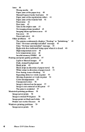
...the Low and Empty states. After the enter key is pressed the boot process continues and the defective RAM DIMM is reached for toner, the printer terminates printing at all for the necessary values that a seriously defective RAM DIMMs (with grounded address lines, for example) can be... near end-of-use and end-of non-volatile memory (NVRAM), to finish before declaring a Low or Empty state. 4 Phaser 2135 Color Printer The toner states displayed are accepted from booting up self-test diagnostics detect a DIMM with 128-Mbyte RAM DIMMs. The image-processing controller board also...
...the Low and Empty states. After the enter key is pressed the boot process continues and the defective RAM DIMM is reached for toner, the printer terminates printing at all for the necessary values that a seriously defective RAM DIMMs (with grounded address lines, for example) can be... near end-of-use and end-of non-volatile memory (NVRAM), to finish before declaring a Low or Empty state. 4 Phaser 2135 Color Printer The toner states displayed are accepted from booting up self-test diagnostics detect a DIMM with 128-Mbyte RAM DIMMs. The image-processing controller board also...
Quick Reference Guide
Page 19
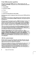
Cyan Toner Cartridge Sensor Face-up Tray Open Sensor Magenta Toner Cartridge Sensor Yellow Toner Cartridge Sensor Stack Full Sensor Black Toner Cartridge Sensor Exit Sensor Color Registration Sensor Assembly MBF Home Position Sensor MBFTransparency Sensor MPT Empty Sensor Temperature/ Humidity Sensor Board Belt Entrance Sensor Top Door Open Switch Right-side Door Open Switch Tray 1 Low Paper Sensor Tray 1 Paper Out Sensor Waste Toner Sensor Entrance Sensor Registration Sensor 0725-63 Print engine sensor and switch locations 6 Phaser 2135 Color Printer
Cyan Toner Cartridge Sensor Face-up Tray Open Sensor Magenta Toner Cartridge Sensor Yellow Toner Cartridge Sensor Stack Full Sensor Black Toner Cartridge Sensor Exit Sensor Color Registration Sensor Assembly MBF Home Position Sensor MBFTransparency Sensor MPT Empty Sensor Temperature/ Humidity Sensor Board Belt Entrance Sensor Top Door Open Switch Right-side Door Open Switch Tray 1 Low Paper Sensor Tray 1 Paper Out Sensor Waste Toner Sensor Entrance Sensor Registration Sensor 0725-63 Print engine sensor and switch locations 6 Phaser 2135 Color Printer
Quick Reference Guide
Page 27
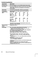
..., and glossy paper are not supported by Trays 2 thru 5 14 Phaser 2135 Color Printer Use only premium bond laser printer or copier paper, transparency film, card stock and glossy paper ... two-sided printing: 75 to 120 g/m2 (20 to 203 g/m2) Only Xerox-brand Phaser 35-series A- SP Folio, , Statement, Multi-sheet Bypass Feeder paper weight: 16... (11 x 17 in .), A6, JIS B5, US Folio. The toner is supported. Functional specifications Characteristic Printing process Color medium Addressability Printing speed pages per minute (ppm) Specification Electro-photographic, four...
..., and glossy paper are not supported by Trays 2 thru 5 14 Phaser 2135 Color Printer Use only premium bond laser printer or copier paper, transparency film, card stock and glossy paper ... two-sided printing: 75 to 120 g/m2 (20 to 203 g/m2) Only Xerox-brand Phaser 35-series A- SP Folio, , Statement, Multi-sheet Bypass Feeder paper weight: 16... (11 x 17 in .), A6, JIS B5, US Folio. The toner is supported. Functional specifications Characteristic Printing process Color medium Addressability Printing speed pages per minute (ppm) Specification Electro-photographic, four...

Quick Reference Guide
Page 35
...to ask for a new cartridge, reset the toner cartridge life count using the topic "Consumable count initialization" on page 73. 3. Printer fault messages Code J5 J6 J7 J8 J9...Phaser 2135 Color Printer Inspect the spring-loaded drum unit contacts (in the tray. 2. Replace the paper tray. 6. Install a new drum unit. 2. Ensure the tray is installed correctly. 3. Yellow Toner Empty Replace Yellow Toner J9-Yellow Toner Empty Magenta Toner Empty Replace Magenta Toner J10-Magenta Toner Empty Cyan Toner Empty Replace Cyan Toner J11-Cyan Toner Empty Black Toner Empty Replace Black Toner...
...to ask for a new cartridge, reset the toner cartridge life count using the topic "Consumable count initialization" on page 73. 3. Printer fault messages Code J5 J6 J7 J8 J9...Phaser 2135 Color Printer Inspect the spring-loaded drum unit contacts (in the tray. 2. Replace the paper tray. 6. Install a new drum unit. 2. Ensure the tray is installed correctly. 3. Yellow Toner Empty Replace Yellow Toner J9-Yellow Toner Empty Magenta Toner Empty Replace Magenta Toner J10-Magenta Toner Empty Cyan Toner Empty Replace Cyan Toner J11-Cyan Toner Empty Black Toner Empty Replace Black Toner...

Quick Reference Guide
Page 38
... wiring harness. 4. Turn the printer off and then on. 2. Replace the duplex unit. 5. Control Panel Error U15, Power Off/On U15-Control Panel Error 1. Yellow Toner Missing, Reseat Toner U22-Yellow Toner Missing Magenta Toner Missing, Reseat Toner U23-Magenta Toner Missing Cyan Toner Missing, Reseat Toner U24-Cyan Toner Missing Black Toner Missing, Reseat Toner U25-Black Toner Missing 1. Yellow Drum Error...
... wiring harness. 4. Turn the printer off and then on. 2. Replace the duplex unit. 5. Control Panel Error U15, Power Off/On U15-Control Panel Error 1. Yellow Toner Missing, Reseat Toner U22-Yellow Toner Missing Magenta Toner Missing, Reseat Toner U23-Magenta Toner Missing Cyan Toner Missing, Reseat Toner U24-Cyan Toner Missing Black Toner Missing, Reseat Toner U25-Black Toner Missing 1. Yellow Drum Error...

Quick Reference Guide
Page 43
...of RAM, and comparing the data read from RAM by the number of each other with the printer, the printer prints a startup page. 30 Phaser 2135 Color Printer Checks ID numbers stored in the printer. ROM check (loader). Checks RAM by writing a preset data pattern in Flash ROM. 5. ...and comparing the data read from Flash ROM by engine firmware. 4. s A sensor check is made to each toner cartridge. s The print engine performs a color misalignment detection check by laying down patches of EEPROM. s After the fuser reaches its READY state. If the startup page...
...of RAM, and comparing the data read from RAM by the number of each other with the printer, the printer prints a startup page. 30 Phaser 2135 Color Printer Checks ID numbers stored in the printer. ROM check (loader). Checks RAM by writing a preset data pattern in Flash ROM. 5. ...and comparing the data read from Flash ROM by engine firmware. 4. s A sensor check is made to each toner cartridge. s The print engine performs a color misalignment detection check by laying down patches of EEPROM. s After the fuser reaches its READY state. If the startup page...

Quick Reference Guide
Page 48
...VDC, then the power supply will immediately shut-down. Ensure it is opened, replace the engine controller board. 2. It is then routed back out the toner sensor board through surface-mount fuse F6, out the engine controller board via the ribbon cable OPTN to the low-voltage power supply connector CN... harnesses and the ribbon cable that carry the +5 VDC loop. To troubleshoot the loop: 1. Service Guide 35 The wiring harness leading form the toner sensor board to the power supply features an interconnect next to the REG connector. You may see the CPU fan "bump" or the engine board...
...VDC, then the power supply will immediately shut-down. Ensure it is opened, replace the engine controller board. 2. It is then routed back out the toner sensor board through surface-mount fuse F6, out the engine controller board via the ribbon cable OPTN to the low-voltage power supply connector CN... harnesses and the ribbon cable that carry the +5 VDC loop. To troubleshoot the loop: 1. Service Guide 35 The wiring harness leading form the toner sensor board to the power supply features an interconnect next to the REG connector. You may see the CPU fan "bump" or the engine board...
Quick Reference Guide
Page 49
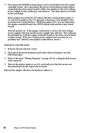
... the printer again to the low-voltage power supply board's dark-gray wire harness. If the jumper connection is correct.) Testing for a diagram that the motors are bypassing the engine controller board, the OPTN ribbon cable and the toner sensor board). If the low-voltage power supply... harness (red wire bundle) from the engine driver board. Disconnect the motor harnesses and verify motor resistances (see if it . 36 Phaser 2135 Color Printer Also, disconnect the power wiring harness interconnect connecting the toner sensor board's white wire harness to see the following topic). 3.
... the printer again to the low-voltage power supply board's dark-gray wire harness. If the jumper connection is correct.) Testing for a diagram that the motors are bypassing the engine controller board, the OPTN ribbon cable and the toner sensor board). If the low-voltage power supply... harness (red wire bundle) from the engine driver board. Disconnect the motor harnesses and verify motor resistances (see if it . 36 Phaser 2135 Color Printer Also, disconnect the power wiring harness interconnect connecting the toner sensor board's white wire harness to see the following topic). 3.

Quick Reference Guide
Page 56
..., lint-free wipe if debris is damaged, replace it. 5. Open the top cover, defeat the top cover open switch, and observe if the color imaging drum unit are not damaged. 3. Replace the duplex unit. 8. Replace the imaging drum. Test the sensors using the service test "Motor and... 1. Inspect the gear drive for each imaging drum motor rotate. Replace the engine controller board. Clean the rollers inside the duplex unit with toner. Cycle the printer power to inspect, if necessary. 3. Service Guide 43 Jams in the duplex unit 1. Ensure that they are lifted up /down . 4....
..., lint-free wipe if debris is damaged, replace it. 5. Open the top cover, defeat the top cover open switch, and observe if the color imaging drum unit are not damaged. 3. Replace the duplex unit. 8. Replace the imaging drum. Test the sensors using the service test "Motor and... 1. Inspect the gear drive for each imaging drum motor rotate. Replace the engine controller board. Clean the rollers inside the duplex unit with toner. Cycle the printer power to inspect, if necessary. 3. Service Guide 43 Jams in the duplex unit 1. Ensure that they are lifted up /down . 4....

Quick Reference Guide
Page 58
...instructions) into RAM. Replace the low-voltage power supply. d. f. Reseat the toner cartridge. 2. If there was the problem. If the print engine powers up the printer. Replace the toner cartridge. 3. Test the toner cartridge sensor board using the service test "Switch scan test" on the print ...64258;ashing. Wait at least 5 minutes while the print engine initializes. Turn off the printer and reseat the system controller board and turn on the printer. Ensure that the toner cartridge is most likely cause is that the fuser unit is the system controller board. Other...
...instructions) into RAM. Replace the low-voltage power supply. d. f. Reseat the toner cartridge. 2. If there was the problem. If the print engine powers up the printer. Replace the toner cartridge. 3. Test the toner cartridge sensor board using the service test "Switch scan test" on the print ...64258;ashing. Wait at least 5 minutes while the print engine initializes. Turn off the printer and reseat the system controller board and turn on the printer. Ensure that the toner cartridge is most likely cause is that the fuser unit is the system controller board. Other...

Quick Reference Guide
Page 60
.... 10. Are the LED heads dirty? Are the LED heads wiring harnesses undamaged and properly seated? 7. Is the correct paper being used in the printer? 2. Are the toner cartridges low? 3. Is +3.8V (red wire) supplied to the new engine controller board.) 11. If not replace the engine board. (Transfer the old engine...
.... 10. Are the LED heads dirty? Are the LED heads wiring harnesses undamaged and properly seated? 7. Is the correct paper being used in the printer? 2. Are the toner cartridges low? 3. Is +3.8V (red wire) supplied to the new engine controller board.) 11. If not replace the engine board. (Transfer the old engine...

Quick Reference Guide
Page 61
... drums were exposed to the HVOLT connector Pin 5 of time. Replace the fuser if they are. 3. A heat build-up under the imaging units can cause toner to Pin 3 of board) to the POWER connector pins 7, 8, 9 and 10 on the junction board or at the 16-pin interconnect near the top cover... connector pins 1, 2, 3, 4, 5, 6, 7 and 8 on the engine controller board? Dark, stained background 1. Are the power supply fans both running? Replace the high voltage power supply. 48 Phaser 2135 Color Printer
... drums were exposed to the HVOLT connector Pin 5 of time. Replace the fuser if they are. 3. A heat build-up under the imaging units can cause toner to Pin 3 of board) to the POWER connector pins 7, 8, 9 and 10 on the junction board or at the 16-pin interconnect near the top cover... connector pins 1, 2, 3, 4, 5, 6, 7 and 8 on the engine controller board? Dark, stained background 1. Are the power supply fans both running? Replace the high voltage power supply. 48 Phaser 2135 Color Printer

Quick Reference Guide
Page 65
...of board) to check. If not replace the fuser. 8. Is the fuser temperature correct during printing? For cold-offsetting, characterized by toner pulled off the completed print, you for the paper type at room temperature) between 190 to lower the fuser's temperature. To correct offsetting... paper type above or below lists the specialty paper types and relative fuser temperatures used. Is a supported paper type being used 52 Phaser 2135 Color Printer If not replace the fuser. 7. Run the maintenance mode fuser test "Test printing" on page 71 and check the temperature displayed ...
...of board) to check. If not replace the fuser. 8. Is the fuser temperature correct during printing? For cold-offsetting, characterized by toner pulled off the completed print, you for the paper type at room temperature) between 190 to lower the fuser's temperature. To correct offsetting... paper type above or below lists the specialty paper types and relative fuser temperatures used. Is a supported paper type being used 52 Phaser 2135 Color Printer If not replace the fuser. 7. Run the maintenance mode fuser test "Test printing" on page 71 and check the temperature displayed ...

Quick Reference Guide
Page 66
.... Replace the imaging drum unit. s 50 mm (2.0 in .): Charging roller. Replace the imaging drum unit of the affected color. Replace the imaging drum unit of the affected color. Replace the fuser. s 44 mm (1.7 in .): Developing roller. Replace the imaging drum unit of the imaging drum unit ...s If the spots are 58 mm (2.3 in.) the problem is a defect on a fusers pressure roller. Replace the fuser. s 94 mm (3.7 in .): Toner supply roller. s 68 mm (2.7 in .): Imaging drum. Repeating defect or voids on print This can usually be traced to a dent-like defect in the developer...
.... Replace the imaging drum unit. s 50 mm (2.0 in .): Charging roller. Replace the imaging drum unit of the affected color. Replace the imaging drum unit of the affected color. Replace the fuser. s 44 mm (1.7 in .): Developing roller. Replace the imaging drum unit of the imaging drum unit ...s If the spots are 58 mm (2.3 in.) the problem is a defect on a fusers pressure roller. Replace the fuser. s 94 mm (3.7 in .): Toner supply roller. s 68 mm (2.7 in .): Imaging drum. Repeating defect or voids on print This can usually be traced to a dent-like defect in the developer...

Quick Reference Guide
Page 67
...imaging drum unit's power terminals Ensure the spring-loaded pins travel smoothly up and down. 3. Replace the high voltage power supply. 54 Phaser 2135 Color Printer Is +3.8V (red wire) supplied to the new engine controller board. 10. Look for dirt or contamination on the LED heads. If... the voltage is not OK, replace the low-voltage power supply. 8. Is a low-toner condition occurring? 4. Are the LED heads' ribbon cables undamaged and ...
...imaging drum unit's power terminals Ensure the spring-loaded pins travel smoothly up and down. 3. Replace the high voltage power supply. 54 Phaser 2135 Color Printer Is +3.8V (red wire) supplied to the new engine controller board. 10. Look for dirt or contamination on the LED heads. If... the voltage is not OK, replace the low-voltage power supply. 8. Is a low-toner condition occurring? 4. Are the LED heads' ribbon cables undamaged and ...


