
Installation Instructions
Page 1
... and tell you what the potential hazard is, tell you how to Wall 8 Prepare Upper Cabinet 8 Install Damper Assembly 9 Install the Microwave Oven 9 Complete Installation 10 VENTING DESIGN SPECIFICATIONS 11 ASSISTANCE 12 Replacement Parts 12 Accessories 12 MICROWAVE HOOD COMBINATION SAFETY Your safety and... the safety of your appliance. See "Installation Requirements" section for use above electric or gas cooking products up to potential hazards that can be killed or seriously ...
... and tell you what the potential hazard is, tell you how to Wall 8 Prepare Upper Cabinet 8 Install Damper Assembly 9 Install the Microwave Oven 9 Complete Installation 10 VENTING DESIGN SPECIFICATIONS 11 ASSISTANCE 12 Replacement Parts 12 Accessories 12 MICROWAVE HOOD COMBINATION SAFETY Your safety and... the safety of your appliance. See "Installation Requirements" section for use above electric or gas cooking products up to potential hazards that can be killed or seriously ...

Installation Instructions
Page 2
...metal screws (2) G. The piece inside the perforation is for weight of the cardboard packaging. 2. See "Electrical Requirements" section. For Roof Venting Installation Only: ■ If you are using a rectangular to round transition piece, the 3" (7.6 cm) clearance needs to exist above the microwave oven so...which includes microwave oven and items placed inside the microwave oven and upper cabinet. ■ Grounded electrical outlet inside upper cabinet. See "Installation Dimensions" illustration. ■ Minimum one 2" x 4" (50.8 x 101.6 mm) wood wall stud and minimum 3/8" (10 mm)...
...metal screws (2) G. The piece inside the perforation is for weight of the cardboard packaging. 2. See "Electrical Requirements" section. For Roof Venting Installation Only: ■ If you are using a rectangular to round transition piece, the 3" (7.6 cm) clearance needs to exist above the microwave oven so...which includes microwave oven and items placed inside the microwave oven and upper cabinet. ■ Grounded electrical outlet inside upper cabinet. See "Installation Dimensions" illustration. ■ Minimum one 2" x 4" (50.8 x 101.6 mm) wood wall stud and minimum 3/8" (10 mm)...

Installation Instructions
Page 3
...plug. A. 2" x 4" wall stud B. Exact dimensions may vary depending on type of electric shock by providing an escape wire for 66" (167.6 cm) installation height. Do not use an extension cord. Failure to whether the microwave oven is properly grounded. Required: ■ A 120 Volt, 60 Hz, AC only... doubt exists as to follow these instructions can result in a risk of the grounding plug can result in death, fire, or electrical shock. Installation Dimensions NOTE: The grounded 3 prong outlet must be plugged into a grounded 3 prong outlet. Do not use of electric shock. Do not ...
...plug. A. 2" x 4" wall stud B. Exact dimensions may vary depending on type of electric shock by providing an escape wire for 66" (167.6 cm) installation height. Do not use an extension cord. Failure to whether the microwave oven is properly grounded. Required: ■ A 120 Volt, 60 Hz, AC only... doubt exists as to follow these instructions can result in a risk of the grounding plug can result in death, fire, or electrical shock. Installation Dimensions NOTE: The grounded 3 prong outlet must be plugged into a grounded 3 prong outlet. Do not use of electric shock. Do not ...

Installation Instructions
Page 4
... Slots 8. Blower motor 5. Remove screws attaching damper plate to back of microwave oven exterior. Make sure damper plate tabs are using recirculation installation. If the mounting plate is reinstalled in Step 1. 4 Tape the microwave oven door closed so that exhaust ports face the back of ... the back of microwave oven with 2 screws removed in another location where wall or roof venting may be used. Damper plate 2. INSTALLATION INSTRUCTIONS Remove Mounting Plate Depending on your model, the mounting plate may be in recessed holes) D A. A A. NOTE: To avoid...
... Slots 8. Blower motor 5. Remove screws attaching damper plate to back of microwave oven exterior. Make sure damper plate tabs are using recirculation installation. If the mounting plate is reinstalled in Step 1. 4 Tape the microwave oven door closed so that exhaust ports face the back of ... the back of microwave oven with 2 screws removed in another location where wall or roof venting may be used. Damper plate 2. INSTALLATION INSTRUCTIONS Remove Mounting Plate Depending on your model, the mounting plate may be in recessed holes) D A. A A. NOTE: To avoid...

Installation Instructions
Page 5
...If blower motor is not correctly oriented, the 2 screws removed in Step 1 of "Wall Venting Installation Only." 5 Damper plate B. Screws C. Repeat Step 1 from "Wall Venting Installation Only." 5. Repeat Step 3 from "Wall Venting Installation Only." 3. Reattach blower motor to the microwave oven. 7. A B C A. Damper plate ... top of microwave oven. NOTE: If blower motor is not positioned with flat sides facing the back of "Wall Venting Installation Only." A 6. Securely tighten screws. Slots 8. Reattach damper plate. Rotate blower motor so that exhaust ports face the top...
...If blower motor is not correctly oriented, the 2 screws removed in Step 1 of "Wall Venting Installation Only." 5 Damper plate B. Screws C. Repeat Step 1 from "Wall Venting Installation Only." 5. Repeat Step 3 from "Wall Venting Installation Only." 3. Reattach blower motor to the microwave oven. 7. A B C A. Damper plate ... top of microwave oven. NOTE: If blower motor is not positioned with flat sides facing the back of "Wall Venting Installation Only." A 6. Securely tighten screws. Slots 8. Reattach damper plate. Rotate blower motor so that exhaust ports face the top...

Installation Instructions
Page 6
...and draw a plumb line down each stud center. Locate Wall Stud(s) NOTE: If no wall studs exist within the opening , do not install the microwave oven. 1. End holes (on mounting plate) B. Support tabs F. Using a stud finder, locate the edges of the vertical ...centerline (see "Mark Rear Wall" section), only recirculation or roof venting installation can be done. Wall Stud at One End Hole Figure 3 Wall Studs at End Holes Figure 2 B C C C D B D A A A A E E E E F F NOTE:...
...and draw a plumb line down each stud center. Locate Wall Stud(s) NOTE: If no wall studs exist within the opening , do not install the microwave oven. 1. End holes (on mounting plate) B. Support tabs F. Using a stud finder, locate the edges of the vertical ...centerline (see "Mark Rear Wall" section), only recirculation or roof venting installation can be done. Wall Stud at One End Hole Figure 3 Wall Studs at End Holes Figure 2 B C C C D B D A A A A E E E E F F NOTE:...

Installation Instructions
Page 7
...end holes marked in Step 8, and mark. 11. Drill 3/16" (5 mm) hole(s) into the wall stud(s) at both end holes are 3 installation configurations. D. Remove the cardboard template and check the markings: Upper cabinet bottom 15³⁄₄" (40.0 cm) Centerline 17¹⁄₄"... cabinet, and must be level. ■ The end holes must be 15³⁄₄" (40.0 cm) from the mark made in Step 4. Wall Venting Installation Only Upper cabinet bottom ³⁄₈" (1 cm) 4" (10.2 cm) Centerline 6" (15.2 cm) 6" (15.2 cm) 8. Using a straightedge, draw ...
...end holes marked in Step 8, and mark. 11. Drill 3/16" (5 mm) hole(s) into the wall stud(s) at both end holes are 3 installation configurations. D. Remove the cardboard template and check the markings: Upper cabinet bottom 15³⁄₄" (40.0 cm) Centerline 17¹⁄₄"... cabinet, and must be level. ■ The end holes must be 15³⁄₄" (40.0 cm) from the mark made in Step 4. Wall Venting Installation Only Upper cabinet bottom ³⁄₈" (1 cm) 4" (10.2 cm) Centerline 6" (15.2 cm) 6" (15.2 cm) 8. Using a straightedge, draw ...

Installation Instructions
Page 8
... x 2" lag screws. Wall Studs at Both End Holes (Figure 4) 1. Securely tighten the lag screws. Drywall 5. Drill a 3/4" (19 mm) hole through both ends. 1. Installation for Wall Studs at Both End Holes (Figure 4) 1. Leave enough space for the toggle nuts to open . 3. B A C A. 1/4-20 x 3" round-head bolt B. ...section. 8 Upper-cabinet template D 10" (25.4 cm) F E 10" G (25.4 cm) Spring toggle nut 3. With the support tabs of "Installation for No Wall Studs at the end holes marked in the top of the tiles rather than the drywall). 4. Make sure the template centerline aligns...
... x 2" lag screws. Wall Studs at Both End Holes (Figure 4) 1. Securely tighten the lag screws. Drywall 5. Drill a 3/4" (19 mm) hole through both ends. 1. Installation for Wall Studs at Both End Holes (Figure 4) 1. Leave enough space for the toggle nuts to open . 3. B A C A. 1/4-20 x 3" round-head bolt B. ...section. 8 Upper-cabinet template D 10" (25.4 cm) F E 10" G (25.4 cm) Spring toggle nut 3. With the support tabs of "Installation for No Wall Studs at the end holes marked in the top of the tiles rather than the drywall). 4. Make sure the template centerline aligns...

Installation Instructions
Page 9
...so that damper blade moves freely, and opens fully. 2. IMPORTANT: The control side of microwave oven B. Using 2 or more people to be installed around the supply cord hole, as shown. A. NOTE: If venting through the power supply cord hole in place. 9 These are for two ...A B A. Mounting plate B. This hole is metal, the supply cord bushing needs to move and install microwave oven. Handle the microwave oven gently. 1. Rotate microwave oven up toward upper cabinet. Install Damper Assembly (for the power supply cord. Cut 3/4" (19 mm) hole at the top, and ...
...so that damper blade moves freely, and opens fully. 2. IMPORTANT: The control side of microwave oven B. Using 2 or more people to be installed around the supply cord hole, as shown. A. NOTE: If venting through the power supply cord hole in place. 9 These are for two ...A B A. Mounting plate B. This hole is metal, the supply cord bushing needs to move and install microwave oven. Handle the microwave oven gently. 1. Rotate microwave oven up toward upper cabinet. Install Damper Assembly (for the power supply cord. Cut 3/4" (19 mm) hole at the top, and ...

Installation Instructions
Page 10
...grounded 3 prong outlet. 3. Reconnect power. 4. Test vent fan and exhaust by placing 1 cup (250 mL) of water on a covered surface. 8. Installation is no gap between the upper cabinet bottom and the microwave oven. A B A. Do not use an extension cord. If adjustment is plugged into microwave oven... vent to follow these instructions can result in place, insert bolts through the cabinet cutout so that the long tab of the microwave oven. Install filters. Refer to the User Instructions for future use. 10 NOTE: The screw cannot be added. Raised tabs B. Upper cabinet cutout E. ...
...grounded 3 prong outlet. 3. Reconnect power. 4. Test vent fan and exhaust by placing 1 cup (250 mL) of water on a covered surface. 8. Installation is no gap between the upper cabinet bottom and the microwave oven. A B A. Do not use an extension cord. If adjustment is plugged into microwave oven... vent to follow these instructions can result in place, insert bolts through the cabinet cutout so that the long tab of the microwave oven. Install filters. Refer to the User Instructions for future use. 10 NOTE: The screw cannot be added. Raised tabs B. Upper cabinet cutout E. ...

Installation Instructions
Page 11
... the vent system ■ using caulking compound to seal exterior wall or roof opening around cap ■ not installing 2 elbows together, for optimal hood performance If venting through the roof, and rectangular to round transition is used,...;" x 10" = 25 ft (8.3 x 25.4 cm = 7.6 m) D. 90° elbow: 6" = 10 ft (15.2 cm = 3 m) E. For optimal venting installation, we recommend: ■ using recirculation installation. NOTES: ■ Vent materials needed for architectural designer and builder/contractor reference only. Vent extension piece, at least 3" (7.6 cm) of clearance between the...
... the vent system ■ using caulking compound to seal exterior wall or roof opening around cap ■ not installing 2 elbows together, for optimal hood performance If venting through the roof, and rectangular to round transition is used,...;" x 10" = 25 ft (8.3 x 25.4 cm = 7.6 m) D. 90° elbow: 6" = 10 ft (15.2 cm = 3 m) E. For optimal venting installation, we recommend: ■ using recirculation installation. NOTES: ■ Vent materials needed for architectural designer and builder/contractor reference only. Vent extension piece, at least 3" (7.6 cm) of clearance between the...

Installation Instructions
Page 12
For best performance, use when installing this microwave oven in a 36" (91.4 cm) or 42" (106.7 cm) wide opening , behind the microwave oven door on the model and serial number plate, ... need the microwave oven model number and serial number. You will need your authorized dealer or service center for either type of the installation hardware needs to be installed to round transition piece = 5 ft (1.5 m) D. 2 ft (0.6 m) + 6 ft (1.8 m) straight = 8 ft (2.4 m) If the existing vent is a list of the system you need additional assistance, call...
For best performance, use when installing this microwave oven in a 36" (91.4 cm) or 42" (106.7 cm) wide opening , behind the microwave oven door on the model and serial number plate, ... need the microwave oven model number and serial number. You will need your authorized dealer or service center for either type of the installation hardware needs to be installed to round transition piece = 5 ft (1.5 m) D. 2 ft (0.6 m) + 6 ft (1.8 m) straight = 8 ft (2.4 m) If the existing vent is a list of the system you need additional assistance, call...
Dimension Guide
Page 1
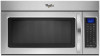
...2 ft (0.6 m) C A. Vent extension piece, at least 3" (7.6 cm) high Because Whirlpool Corporation policy includes a continuous commitment to round transition piece so that a separate circuit serving only...WMH1162XV WMH1163XV WMH1164XW WMH2175XV WMH2205XV WMH3205XV WMH31017A WMH32517A WMH53520A WMH32L19A WMH73L20A Electrical: A 120-Volt, 60-Hz, AC...system = 73 ft (22.2 m) total A B 6 ft (1.8 m) A. 2" x 4" wall stud B. For complete details, see Installation our products, we reserve the right to change materials and specifications without notice. Wall cap F E. 3 " x 10" to 6" ...
...2 ft (0.6 m) C A. Vent extension piece, at least 3" (7.6 cm) high Because Whirlpool Corporation policy includes a continuous commitment to round transition piece so that a separate circuit serving only...WMH1162XV WMH1163XV WMH1164XW WMH2175XV WMH2205XV WMH3205XV WMH31017A WMH32517A WMH53520A WMH32L19A WMH73L20A Electrical: A 120-Volt, 60-Hz, AC...system = 73 ft (22.2 m) total A B 6 ft (1.8 m) A. 2" x 4" wall stud B. For complete details, see Installation our products, we reserve the right to change materials and specifications without notice. Wall cap F E. 3 " x 10" to 6" ...
Warranty Information
Page 1
...800-253-1301. All rights reserved. ® Registered Trademark/TM Trademark of Whirlpool, U.S.A. 1/12 Printed in an inaccessible location or is covered by the customer. Service calls to correct the installation of your major appliance, unless such damage results from defects in the United States... removed, altered or cannot be repaired in the home and only in-home service is not installed in accordance with the product, Whirlpool Corporation or Whirlpool Canada LP (hereafter "Whirlpool") will pay for future reference. This major appliance is designed to be easily determined. Have ...
...800-253-1301. All rights reserved. ® Registered Trademark/TM Trademark of Whirlpool, U.S.A. 1/12 Printed in an inaccessible location or is covered by the customer. Service calls to correct the installation of your major appliance, unless such damage results from defects in the United States... removed, altered or cannot be repaired in the home and only in-home service is not installed in accordance with the product, Whirlpool Corporation or Whirlpool Canada LP (hereafter "Whirlpool") will pay for future reference. This major appliance is designed to be easily determined. Have ...
Use & Care Guide
Page 1
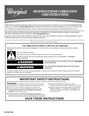
...words mean: DANGER You can be grounded. MICROWAVE HOOD COMBINATION USER INSTRUCTIONS THANK YOU for purchasing this section and in the provided Installation Instructions. If you don't immediately follow instructions. Para obtener acceso a "Instrucciones para el usuario de la combinación microondas ...exposure to potential hazards that can happen if the instructions are not followed. You will need assistance, call us at www.whirlpool.com for example, closed glass jars - are very important. Always read and obey all instructions before using the microwave oven...
...words mean: DANGER You can be grounded. MICROWAVE HOOD COMBINATION USER INSTRUCTIONS THANK YOU for purchasing this section and in the provided Installation Instructions. If you don't immediately follow instructions. Para obtener acceso a "Instrucciones para el usuario de la combinación microondas ...exposure to potential hazards that can happen if the instructions are not followed. You will need assistance, call us at www.whirlpool.com for example, closed glass jars - are very important. Always read and obey all instructions before using the microwave oven...
Use & Care Guide
Page 3
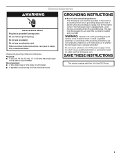
...delay fuse or time-delay circuit breaker. ■ A separate circuit serving only this microwave oven. If the power supply cord is properly installed and grounded. Do not use an extension cord. GROUNDING INSTRUCTIONS ■ For all governing codes and ordinances. Failure to whether the microwave ... risk of electric shock. Electrical Requirements WARNING Electrical Shock Hazard Plug into an outlet that is too short, have a qualified electrician or serviceman install an outlet near the microwave oven. Required: ■ A 120 volt, 60 Hz, AC only, 15- or 20-amp electrical supply ...
...delay fuse or time-delay circuit breaker. ■ A separate circuit serving only this microwave oven. If the power supply cord is properly installed and grounded. Do not use an extension cord. GROUNDING INSTRUCTIONS ■ For all governing codes and ordinances. Failure to whether the microwave ... risk of electric shock. Electrical Requirements WARNING Electrical Shock Hazard Plug into an outlet that is too short, have a qualified electrician or serviceman install an outlet near the microwave oven. Required: ■ A 120 volt, 60 Hz, AC only, 15- or 20-amp electrical supply ...
Use & Care Guide
Page 6
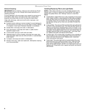
... area - Close bulb cover, replace vent grille, and secure with mild soap, water and a soft cloth or sponge, or as prompted by filter status indicator. Installing/Replacing Filters and Light Bulbs NOTE: A filter status indicator (on some models) appears in the display when it out. Remove two screws on the vent...
... area - Close bulb cover, replace vent grille, and secure with mild soap, water and a soft cloth or sponge, or as prompted by filter status indicator. Installing/Replacing Filters and Light Bulbs NOTE: A filter status indicator (on some models) appears in the display when it out. Remove two screws on the vent...
Use & Care Guide
Page 8
... or removed from accident, alteration, misuse, abuse, fire, flood, acts of God, improper installation, installation not in accordance with the product, Whirlpool Corporation or Whirlpool Canada LP (hereafter "Whirlpool") will pay for other damage to the finish of your major appliance is used for Factory...or plumbing codes, or use of consumables or cleaning products not approved by Whirlpool. 5. ITEMS EXCLUDED FROM WARRANTY This limited warranty does not cover: 1. Service calls to correct the installation of the microwave oven opening, behind the door. Damage resulting from your ...
... or removed from accident, alteration, misuse, abuse, fire, flood, acts of God, improper installation, installation not in accordance with the product, Whirlpool Corporation or Whirlpool Canada LP (hereafter "Whirlpool") will pay for other damage to the finish of your major appliance is used for Factory...or plumbing codes, or use of consumables or cleaning products not approved by Whirlpool. 5. ITEMS EXCLUDED FROM WARRANTY This limited warranty does not cover: 1. Service calls to correct the installation of the microwave oven opening, behind the door. Damage resulting from your ...
