Installation Guide
Page 1
...important. Always read and obey all safety messages. This symbol alerts you to Wall 7 Prepare Upper Cabinet 8 Install Damper Assembly 8 Install the Microwave Oven 9 Complete Installation 10 VENTING DESIGN SPECIFICATIONS 11 ASSISTANCE 12 Replacement Parts 12 Accessories 12 SÉCURITÉ DE L'ENSEMBLE FOUR &#...particular model may differ slightly from the illustration in this manual and on your appliance. The appearance of others . See "Installation Requirements" section for use above electric or gas cooking products up to reduce the chance of injury, and tell you don...
...important. Always read and obey all safety messages. This symbol alerts you to Wall 7 Prepare Upper Cabinet 8 Install Damper Assembly 8 Install the Microwave Oven 9 Complete Installation 10 VENTING DESIGN SPECIFICATIONS 11 ASSISTANCE 12 Replacement Parts 12 Accessories 12 SÉCURITÉ DE L'ENSEMBLE FOUR &#...particular model may differ slightly from the illustration in this manual and on your appliance. The appearance of others . See "Installation Requirements" section for use above electric or gas cooking products up to reduce the chance of injury, and tell you don...

Installation Guide
Page 2
... Instructions.) NOTE: Depending on model, aluminum grease filter and charcoal filter may not be combined. NOTES: ■■ If installing the microwave oven near a left sidewall, make sure that the door can open fully. ■■ Some cabinet and building...screws (2) F. Read and follow the instructions provided with your builder or cabinet supplier to back of microwave oven) ■■ Cardboard template (part of installation. For other damages. A B C D E FG H A. Location Requirements Check the opening . ■■ Support for wall or roof venting) ...
... Instructions.) NOTE: Depending on model, aluminum grease filter and charcoal filter may not be combined. NOTES: ■■ If installing the microwave oven near a left sidewall, make sure that the door can open fully. ■■ Some cabinet and building...screws (2) F. Read and follow the instructions provided with your builder or cabinet supplier to back of microwave oven) ■■ Cardboard template (part of installation. For other damages. A B C D E FG H A. Location Requirements Check the opening . ■■ Support for wall or roof venting) ...

Installation Guide
Page 3
...extension cord. Required: ■■ A 120 volt, 60 Hz, AC only, 15- Grounded 3 prong outlet *30" (76.2 cm) is properly installed and grounded. WARNING: Improper use an extension cord. SAVE THESE INSTRUCTIONS 3 Recommended: ■■ A time-delay fuse or time-delay circuit breaker. ■...of the grounding plug can result in a risk of electric shock by providing an escape wire for 66" (167.6 cm) installation height. Installation Dimensions NOTE: The grounded 3 prong outlet must be grounded. Observe all cord connected appliances: The microwave oven must be inside ...
...extension cord. Required: ■■ A 120 volt, 60 Hz, AC only, 15- Grounded 3 prong outlet *30" (76.2 cm) is properly installed and grounded. WARNING: Improper use an extension cord. SAVE THESE INSTRUCTIONS 3 Recommended: ■■ A time-delay fuse or time-delay circuit breaker. ■...of the grounding plug can result in a risk of electric shock by providing an escape wire for 66" (167.6 cm) installation height. Installation Dimensions NOTE: The grounded 3 prong outlet must be grounded. Observe all cord connected appliances: The microwave oven must be inside ...
Installation Guide
Page 4
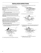
...the back of the microwave oven. Make sure damper plate tabs are using recirculation installation. A A. Repeat Step 1 from "Wall Venting Installation Only." Repeat Step 4 from "Wall Venting Installation Only." 2. If the mounting plate is being handled. Damper plate B. Repeat ...To avoid damage to the venting system. Remove 2 screws attaching blower motor to top of microwave oven. Exhaust port A 6. Wall Venting Installation Only 1. NOTE: To avoid possible damage, cover the work surface. 1. Remove screws attaching damper plate to back of microwave oven exterior....
...the back of the microwave oven. Make sure damper plate tabs are using recirculation installation. A A. Repeat Step 1 from "Wall Venting Installation Only." Repeat Step 4 from "Wall Venting Installation Only." 2. If the mounting plate is being handled. Damper plate B. Repeat ...To avoid damage to the venting system. Remove 2 screws attaching blower motor to top of microwave oven. Exhaust port A 6. Wall Venting Installation Only 1. NOTE: To avoid possible damage, cover the work surface. 1. Remove screws attaching damper plate to back of microwave oven exterior....

Installation Guide
Page 5
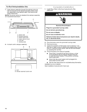
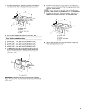
... Configurations." 1. Make sure damper plate tabs are inserted into microwave oven. Screws C. Slots 8. See illustrations in the top of "Wall Venting Installation Only." No Wall Studs at End Holes No Wall Studs at End Holes Figure 4 B D B A A,D A,D A,D E E E ...stud centerlines D. Exhaust port IMPORTANT: If blower motor is within 6" (15.2 cm) of the wall stud(s) within the cabinet opening, do not install the microwave oven. Securely tighten screws. Using a stud finder, locate the edges of the vertical centerline (see "Mark Rear Wall" section), only ...
... Configurations." 1. Make sure damper plate tabs are inserted into microwave oven. Screws C. Slots 8. See illustrations in the top of "Wall Venting Installation Only." No Wall Studs at End Holes No Wall Studs at End Holes Figure 4 B D B A A,D A,D A,D E E E ...stud centerlines D. Exhaust port IMPORTANT: If blower motor is within 6" (15.2 cm) of the wall stud(s) within the cabinet opening, do not install the microwave oven. Securely tighten screws. Using a stud finder, locate the edges of the vertical centerline (see "Mark Rear Wall" section), only ...

Installation Guide
Page 6
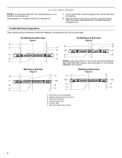
...the mounting plate in place, find and clearly mark the vertical centerline of upper cabinet 3. Set the mounting plate aside. 2. For Wall Venting Installation Only: Upper cabinet bottom ³⁄₈" (1 cm) NOTES: ■■ If the front edge of the upper cabinet is lower... the bottom edge of 1 lag screw, preferably 2. 1. A A. Centerline 6. Top of cardboard template must each other. They must align with each be installed on the wall, making sure it is level, and that its bottom edge is level. D A C B A. These represent the mounting plate's end ...
...the mounting plate in place, find and clearly mark the vertical centerline of upper cabinet 3. Set the mounting plate aside. 2. For Wall Venting Installation Only: Upper cabinet bottom ³⁄₈" (1 cm) NOTES: ■■ If the front edge of the upper cabinet is lower... the bottom edge of 1 lag screw, preferably 2. 1. A A. Centerline 6. Top of cardboard template must each other. They must align with each be installed on the wall, making sure it is level, and that its bottom edge is level. D A C B A. These represent the mounting plate's end ...

Installation Guide
Page 7
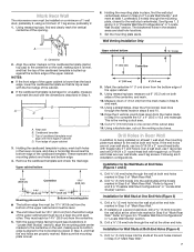
...x 3" round-head bolts and toggle nuts or Z\v x 2" lag screws. Drill a C\zn" (5 mm) hole into wall stud(s) in Step 2 of "Installation for No Wall Studs at Both End Holes (Figure 4) 1. Push the 2 bolts with toggle nut; Spring toggle nut D. Check alignment of "Mark Rear Wall."... . With the support tabs of the mounting plate facing forward, insert C\zn-24 x 3" round-head bolts through both end holes are 3 installation configurations. Mounting plate C. Spring toggle nut 3. Leave enough space for Wall Studs at One End Hole (Figure 3) 1. Wall Stud at Both ...
...x 3" round-head bolts and toggle nuts or Z\v x 2" lag screws. Drill a C\zn" (5 mm) hole into wall stud(s) in Step 2 of "Installation for No Wall Studs at Both End Holes (Figure 4) 1. Push the 2 bolts with toggle nut; Spring toggle nut D. Check alignment of "Mark Rear Wall."... . With the support tabs of the mounting plate facing forward, insert C\zn-24 x 3" round-head bolts through both end holes are 3 installation configurations. Mounting plate C. Spring toggle nut 3. Leave enough space for Wall Studs at One End Hole (Figure 3) 1. Wall Stud at Both ...

Installation Guide
Page 8
...hole is at points "D" and "E" on the rear wall. NOTES: ■■ If the upper cabinet has a frame around the supply cord hole as installed) has a partial wall covering (for example, tile backsplash), be against the upper cabinet bottom. Cut C\v" (19 mm) hole at the circular shaded area ...upper cabinet align with the holes in the top of the upper cabinet, and attach with 2 sheet metal screws. Power supply cord bushing 6. Install Damper Assembly (for the power supply cord. Back of the shaded rectangular area "F" on the template. Cut the 1¹⁄₂" (3.8 cm...
...hole is at points "D" and "E" on the rear wall. NOTES: ■■ If the upper cabinet has a frame around the supply cord hole as installed) has a partial wall covering (for example, tile backsplash), be against the upper cabinet bottom. Cut C\v" (19 mm) hole at the circular shaded area ...upper cabinet align with the holes in the top of the upper cabinet, and attach with 2 sheet metal screws. Power supply cord bushing 6. Install Damper Assembly (for the power supply cord. Back of the shaded rectangular area "F" on the template. Cut the 1¹⁄₂" (3.8 cm...

Installation Guide
Page 9
... warp the top of the microwave oven is being handled. To avoid warping, wood filler blocks (installer to move and install microwave oven. Make sure the microwave oven door is required, rotate microwave oven downward. Install the Microwave Oven WARNING Excessive Weight Hazard Use two or more people to provide) may be added...
... warp the top of the microwave oven is being handled. To avoid warping, wood filler blocks (installer to move and install microwave oven. Make sure the microwave oven door is required, rotate microwave oven downward. Install the Microwave Oven WARNING Excessive Weight Hazard Use two or more people to provide) may be added...
Installation Guide
Page 10
...circuit breaker. Long tab F. Do not use an adapter. Check the operation of microwave oven by operating the vent fan. 5. Installation is not positioned as shown. Install filters. Damper assembly (under the raised tabs of 1 minute at 100% power. If the microwave oven does not operate: &#...to follow these instructions can result in death, fire, or electrical shock. 2. Do not remove ground prong. For Roof Venting Installation Only 1. Insert damper assembly through the cabinet cutout so that a circuit breaker has not tripped. Then secure with sheet metal screw...
...circuit breaker. Long tab F. Do not use an adapter. Check the operation of microwave oven by operating the vent fan. 5. Installation is not positioned as shown. Install filters. Damper assembly (under the raised tabs of 1 minute at 100% power. If the microwave oven does not operate: &#...to follow these instructions can result in death, fire, or electrical shock. 2. Do not remove ground prong. For Roof Venting Installation Only 1. Insert damper assembly through the cabinet cutout so that a circuit breaker has not tripped. Then secure with sheet metal screw...

Installation Guide
Page 11
...E 3" (7.6 cm) F A. diameter round vent C. Do not vent exhaust air into concealed spaces, such as spaces within the wall for installation are for wall venting only) D. If venting through the wall, be sure that there is proper clearance within walls or ceilings, attics, crawl... Transition NOTE: The minimum 3" (7.6 cm) clearance must exist between the top of the microwave oven and the rectangular to vent air outside, unless using recirculation installation. Roof cap: 3¹⁄₄" x 10" = 24 ft (8.3 x 25.4 cm = 7.3 m) C. 90° elbow: 3¹\₄" x 10" = 25 ft (8.3 x 25...
...E 3" (7.6 cm) F A. diameter round vent C. Do not vent exhaust air into concealed spaces, such as spaces within the wall for installation are for wall venting only) D. If venting through the wall, be sure that there is proper clearance within walls or ceilings, attics, crawl... Transition NOTE: The minimum 3" (7.6 cm) clearance must exist between the top of the microwave oven and the rectangular to vent air outside, unless using recirculation installation. Roof cap: 3¹⁄₄" x 10" = 24 ft (8.3 x 25.4 cm = 7.3 m) C. 90° elbow: 3¹\₄" x 10" = 25 ft (8.3 x 25...

Installation Guide
Page 12
... in the "Tools and Parts" section) A A. Accessories Filler Panel Kits are available from sticking. For best performance, use when installing this microwave oven in pairs. To calculate the length of the system you will need , add the equivalent lengths of the microwave oven...on the front facing of vent. ASSISTANCE Call your authorized dealer or service center for details. 12 Replacement Parts If any of the installation hardware needs to be installed to round transition piece must not exceed the equivalent of 140 ft (42.7 m) for equivalent lengths. Two 90° elbows ...
... in the "Tools and Parts" section) A A. Accessories Filler Panel Kits are available from sticking. For best performance, use when installing this microwave oven in pairs. To calculate the length of the system you will need , add the equivalent lengths of the microwave oven...on the front facing of vent. ASSISTANCE Call your authorized dealer or service center for details. 12 Replacement Parts If any of the installation hardware needs to be installed to round transition piece must not exceed the equivalent of 140 ft (42.7 m) for equivalent lengths. Two 90° elbows ...
Dimension Guide
Page 1
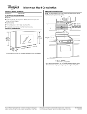
...typical* 12" (30.5 cm) min. 14" (35.6 cm) max. Dimensions are for 66" (167.6 cm) installation height. For complete details, see Installation Instructions packed with a fuse or circuit breaker. Specifications subject to change without notice. W10823831A 06/30/2016 Exact dimensions may vary... REQUIREMENTS Required: ■■ A 120 volt, 60 Hz, AC only, 15- A. 2" x 4" wall stud B. Because Whirlpool Corporation includes a continuous commitment to improve our products, we reserve the right to change materials and specifications without notice. Recommended: ■...
...typical* 12" (30.5 cm) min. 14" (35.6 cm) max. Dimensions are for 66" (167.6 cm) installation height. For complete details, see Installation Instructions packed with a fuse or circuit breaker. Specifications subject to change without notice. W10823831A 06/30/2016 Exact dimensions may vary... REQUIREMENTS Required: ■■ A 120 volt, 60 Hz, AC only, 15- A. 2" x 4" wall stud B. Because Whirlpool Corporation includes a continuous commitment to improve our products, we reserve the right to change materials and specifications without notice. Recommended: ■...
Installation Guide
Page 1
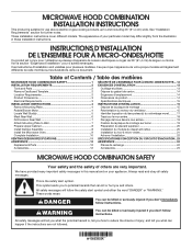
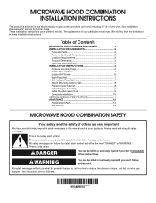
... safety messages will tell you what can kill or hurt you to Wall 8 Prepare Upper Cabinet 8 Install Damper Assembly 9 Install the Microwave Oven 9 Complete Installation 10 VENTING DESIGN SPECIFICATIONS 11 ASSISTANCE 12 Replacement Parts 12 Accessories 12 MICROWAVE HOOD COMBINATION SAFETY Your safety ...and the safety of injury, and tell you what the potential hazard is the safety alert symbol. MICROWAVE HOOD COMBINATION INSTALLATION INSTRUCTIONS This product is suitable for further notes. We have provided many important safety messages in Rear Wall 7 Attach Mounting...
... safety messages will tell you what can kill or hurt you to Wall 8 Prepare Upper Cabinet 8 Install Damper Assembly 9 Install the Microwave Oven 9 Complete Installation 10 VENTING DESIGN SPECIFICATIONS 11 ASSISTANCE 12 Replacement Parts 12 Accessories 12 MICROWAVE HOOD COMBINATION SAFETY Your safety ...and the safety of injury, and tell you what the potential hazard is the safety alert symbol. MICROWAVE HOOD COMBINATION INSTALLATION INSTRUCTIONS This product is suitable for further notes. We have provided many important safety messages in Rear Wall 7 Attach Mounting...
Installation Guide
Page 2
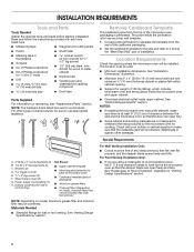
...; C\v" (19 mm) hole saw ■■ Duct tape Parts Supplied For information on model, charcoal filters may be included. See "Installation Dimensions" illustration. ■■ Minimum one 2" x 4" (50.8 x 101.6 mm) wood wall stud and minimum C\," (10 mm...) thickness drywall or plaster/lath within cabinet opening where the microwave oven will not discolor, delaminate or sustain other types of installation. See "Electrical Requirements" section. A B C D E FG H A. 3/16-24 x 3" round-head bolts (2) B. 1/4-20 x 3" flat-head bolts (2) C. hole drill ...
...; C\v" (19 mm) hole saw ■■ Duct tape Parts Supplied For information on model, charcoal filters may be included. See "Installation Dimensions" illustration. ■■ Minimum one 2" x 4" (50.8 x 101.6 mm) wood wall stud and minimum C\," (10 mm...) thickness drywall or plaster/lath within cabinet opening where the microwave oven will not discolor, delaminate or sustain other types of installation. See "Electrical Requirements" section. A B C D E FG H A. 3/16-24 x 3" round-head bolts (2) B. 1/4-20 x 3" flat-head bolts (2) C. hole drill ...
Installation Guide
Page 3
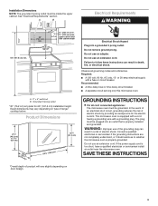
...Improper use an adapter. See "Electrical Requirements" section. Do not use an extension cord. Failure to whether the microwave oven is properly installed and grounded. Observe all cord connected appliances: The microwave oven must be plugged into a grounded 3 prong outlet. Recommended: ■■...*Overall depth of electric shock by providing an escape wire for 66" (167.6 cm) installation height. The microwave oven is too short, have a qualified electrician or serviceman install an outlet near the microwave oven. Do not use of the grounding plug can result in...
...Improper use an adapter. See "Electrical Requirements" section. Do not use an extension cord. Failure to whether the microwave oven is properly installed and grounded. Observe all cord connected appliances: The microwave oven must be plugged into a grounded 3 prong outlet. Recommended: ■■...*Overall depth of electric shock by providing an escape wire for 66" (167.6 cm) installation height. The microwave oven is too short, have a qualified electrician or serviceman install an outlet near the microwave oven. Do not use of the grounding plug can result in...
Installation Guide
Page 4
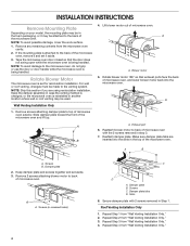
... used. Remove 2 screws attaching blower motor to top of the microwave oven. A Rotate Blower Motor The microwave oven is being handled. 3. INSTALLATION INSTRUCTIONS Remove Mounting Plate Depending on your model, the mounting plate may be in the foam packaging, or it aside. 3. Remove any remaining ...oven cavity. 2. Lift blower motor out of the microwave oven and lift up. NOTE: Skip this section if you are using recirculation installation. Slide damper plate toward the front of microwave oven. Rotate blower motor 180° so that door does not swing open while ...
... used. Remove 2 screws attaching blower motor to top of the microwave oven. A Rotate Blower Motor The microwave oven is being handled. 3. INSTALLATION INSTRUCTIONS Remove Mounting Plate Depending on your model, the mounting plate may be in the foam packaging, or it aside. 3. Remove any remaining ...oven cavity. 2. Lift blower motor out of the microwave oven and lift up. NOTE: Skip this section if you are using recirculation installation. Slide damper plate toward the front of microwave oven. Rotate blower motor 180° so that door does not swing open while ...
Installation Guide
Page 5
...damper plate with 2 screws removed in Step 1 of the microwave oven. Securely tighten screws. A B D A. Repeat Step 1 from "Wall Venting Installation Only." 4. Damper plate tabs D. Make sure damper plate tabs are inserted into the slots in Step 3 cannot be poor. 5 Damper plate B. ...A C D A. Exhaust port IMPORTANT: If blower motor is not correctly oriented, the 2 screws removed in the top of "Wall Venting Installation Only." Reattach damper plate. Reattach blower motor to back of microwave oven with flat sides facing the back of microwave oven. Lower blower motor...
...damper plate with 2 screws removed in Step 1 of the microwave oven. Securely tighten screws. A B D A. Repeat Step 1 from "Wall Venting Installation Only." 4. Damper plate tabs D. Make sure damper plate tabs are inserted into the slots in Step 3 cannot be poor. 5 Damper plate B. ...A C D A. Exhaust port IMPORTANT: If blower motor is not correctly oriented, the 2 screws removed in the top of "Wall Venting Installation Only." Reattach damper plate. Reattach blower motor to back of microwave oven with flat sides facing the back of microwave oven. Lower blower motor...
Installation Guide
Page 6
...F E E F NOTE: If wall stud is within 6" (15.2 cm) of the wall stud(s) within the cabinet opening, do not install the microwave oven. Cabinet opening . 2. Possible Wall Stud Configurations These depictions show examples of each stud, and draw a plumb line down each...stud finder, locate the edges of the vertical centerline (see "Mark Rear Wall" section), only recirculation or roof venting installation can be done. Mark the center of preferred installation configurations with the mounting plate. Support tabs F. Locate Wall Stud(s) NOTE: If no wall studs exist within the opening...
...F E E F NOTE: If wall stud is within 6" (15.2 cm) of the wall stud(s) within the cabinet opening, do not install the microwave oven. Cabinet opening . 2. Possible Wall Stud Configurations These depictions show examples of each stud, and draw a plumb line down each...stud finder, locate the edges of the vertical centerline (see "Mark Rear Wall" section), only recirculation or roof venting installation can be done. Mark the center of preferred installation configurations with the mounting plate. Support tabs F. Locate Wall Stud(s) NOTE: If no wall studs exist within the opening...
Installation Guide
Page 7
...mark. 11. Drill a B\," (16 mm) hole through the wall at Both End Holes (Figure 4) 1. Cardboard template C. or if both end holes are 3 installation configurations. Mark the centerline C\," (1 cm) down 4" (10.2 cm) from the bottom edge of upper cabinet 3. Centerline 2. Using measuring tape, find the wall... stud centerline(s) drawn in Step 6 of 1 lag screw, preferably 2. 1. They must be on a level line with each be installed on a second wall stud, drill a C\zn" (5 mm) hole into the studs at the other . Measure down from the mark made in "Locate Wall...
...mark. 11. Drill a B\," (16 mm) hole through the wall at Both End Holes (Figure 4) 1. Cardboard template C. or if both end holes are 3 installation configurations. Mark the centerline C\," (1 cm) down 4" (10.2 cm) from the bottom edge of upper cabinet 3. Centerline 2. Using measuring tape, find the wall... stud centerline(s) drawn in Step 6 of 1 lag screw, preferably 2. 1. They must be on a level line with each be installed on a second wall stud, drill a C\zn" (5 mm) hole into the studs at the other . Measure down from the mark made in "Locate Wall...


