
Installation Instructions
Page 1
... W10247296B This is suitable for further notes. See "Installation Requirements" section for use above electric or gas cooking products up to Wall 8 Prepare Upper Cabinet 8 Install Damper Assembly 9 Install the Microwave Oven 9 Complete Installation 10 VENTING DESIGN SPECIFICATIONS 11 ASSISTANCE 12 Replacement Parts 12...potential hazards that can happen if the instructions are very important. We have provided many important safety messages in these installation instructions. This symbol alerts you to reduce the chance of others . The appearance of your particular model may ...
... W10247296B This is suitable for further notes. See "Installation Requirements" section for use above electric or gas cooking products up to Wall 8 Prepare Upper Cabinet 8 Install Damper Assembly 9 Install the Microwave Oven 9 Complete Installation 10 VENTING DESIGN SPECIFICATIONS 11 ASSISTANCE 12 Replacement Parts 12...potential hazards that can happen if the instructions are very important. We have provided many important safety messages in these installation instructions. This symbol alerts you to reduce the chance of others . The appearance of your particular model may ...

Installation Instructions
Page 2
...transition piece, the 3" (7.6 cm) clearance needs to use as a rear wall template. 1. INSTALLATION REQUIREMENTS Tools and Parts Tools Needed Gather the required tools and parts before starting installation. See "Installation Dimensions" illustration. ■ Minimum one 2" x 4" (50.8 x 101.6 mm) wood wall...part of packaging) Aluminum grease filters Charcoal filters (Depending on model, aluminum grease filter and charcoal filter may not be installed. See "Electrical Requirements" section. NOTE: The hardware items listed here are not designed to Round Transition" illustration in...
...transition piece, the 3" (7.6 cm) clearance needs to use as a rear wall template. 1. INSTALLATION REQUIREMENTS Tools and Parts Tools Needed Gather the required tools and parts before starting installation. See "Installation Dimensions" illustration. ■ Minimum one 2" x 4" (50.8 x 101.6 mm) wood wall...part of packaging) Aluminum grease filters Charcoal filters (Depending on model, aluminum grease filter and charcoal filter may not be installed. See "Electrical Requirements" section. NOTE: The hardware items listed here are not designed to Round Transition" illustration in...

Installation Instructions
Page 3
...that is properly grounded. Required: ■ A 120 Volt, 60 Hz, AC only, 15- Failure to whether the microwave oven is properly installed and grounded. Product Dimensions 17¹⁄₄" (43.8 cm) 16¹⁄₄" (41.3 cm) (401.05³c⁄₄m")...Do not use an extension cord. Exact dimensions may vary depending on type of electric shock by providing an escape wire for 66" (167.6 cm) installation height. SAVE THESE INSTRUCTIONS 3 Recommended: ■ A time-delay fuse or time-delay circuit breaker. ■ A separate circuit serving only this ...
...that is properly grounded. Required: ■ A 120 Volt, 60 Hz, AC only, 15- Failure to whether the microwave oven is properly installed and grounded. Product Dimensions 17¹⁄₄" (43.8 cm) 16¹⁄₄" (41.3 cm) (401.05³c⁄₄m")...Do not use an extension cord. Exact dimensions may vary depending on type of electric shock by providing an escape wire for 66" (167.6 cm) installation height. SAVE THESE INSTRUCTIONS 3 Recommended: ■ A time-delay fuse or time-delay circuit breaker. ■ A separate circuit serving only this ...

Installation Instructions
Page 4
... recessed holes) D A. Screws B. A A. Damper plate B. Screws C. Damper plate tabs D. Wall Venting Installation Only 1. A B C A. Slots 8. Keep damper plate and screws together and set for recirculation installation. If the mounting plate is set aside. 3. For wall or roof venting, changes must be made to... exterior. NOTE: To avoid damage to the back of the microwave oven. Make sure damper plate tabs are using recirculation installation. Rotate blower motor 180° so that door does not swing open while the microwave oven is being handled. A ...
... recessed holes) D A. Screws B. A A. Damper plate B. Screws C. Damper plate tabs D. Wall Venting Installation Only 1. A B C A. Slots 8. Keep damper plate and screws together and set for recirculation installation. If the mounting plate is set aside. 3. For wall or roof venting, changes must be made to... exterior. NOTE: To avoid damage to the back of the microwave oven. Make sure damper plate tabs are using recirculation installation. Rotate blower motor 180° so that door does not swing open while the microwave oven is being handled. A ...

Installation Instructions
Page 5
... microwave oven. Reattach blower motor to the microwave oven. 7. Securely tighten screws. Damper plate tabs D. Repeat Step 1 from "Wall Venting Installation Only." 3. Secure damper plate with flat sides facing the back of the microwave oven (as shown), performance will be reattached to back of...." 2. Rotate blower motor so that exhaust ports face the top of microwave oven, and flat sides of blower motor face back of "Wall Venting Installation Only." 5 NOTE: If blower motor is not positioned with 2 screws removed in Step 3 cannot be poor. A B C A. Exhaust port ...
... microwave oven. Reattach blower motor to the microwave oven. 7. Securely tighten screws. Damper plate tabs D. Repeat Step 1 from "Wall Venting Installation Only." 3. Secure damper plate with flat sides facing the back of the microwave oven (as shown), performance will be reattached to back of...." 2. Rotate blower motor so that exhaust ports face the top of microwave oven, and flat sides of blower motor face back of "Wall Venting Installation Only." 5 NOTE: If blower motor is not positioned with 2 screws removed in Step 3 cannot be poor. A B C A. Exhaust port ...

Installation Instructions
Page 6
...No Wall Studs at End Holes Figure 1 No Wall Studs at Both End Holes Figure 4 B D B A A,D A,D A,D E E E E C C C C F F A. Cabinet opening , do not install the microwave oven. 1. See illustrations in "Possible Wall Stud Configurations." Holes for lag screws E. Support tabs F. Wall Stud at One End Hole Figure 3 Wall Studs...stud center. Mark the center of the vertical centerline (see "Mark Rear Wall" section), only recirculation or roof venting installation can be done. See illustrations in "Possible Wall Stud Configurations." 2. Wall stud centerlines D.
...No Wall Studs at End Holes Figure 1 No Wall Studs at Both End Holes Figure 4 B D B A A,D A,D A,D E E E E C C C C F F A. Cabinet opening , do not install the microwave oven. 1. See illustrations in "Possible Wall Stud Configurations." Holes for lag screws E. Support tabs F. Wall Stud at One End Hole Figure 3 Wall Studs...stud center. Mark the center of the vertical centerline (see "Mark Rear Wall" section), only recirculation or roof venting installation can be done. See illustrations in "Possible Wall Stud Configurations." 2. Wall stud centerlines D.

Installation Instructions
Page 7
...damaged or unusable, measure and mark the wall with toggle nuts; Measure down from the mark made in the shaded areas are 3 installation configurations. or if both end holes are properly marked. Drill 3/4" (19 mm) holes through the mounting plate, closest to complete ...section. Set the mounting plate aside. Using measuring tape, find the wall stud centerline(s) drawn in Step 3 of "Mark Rear Wall." 2. Centerline 2. Wall Venting Installation Only Upper cabinet bottom ³⁄₈" (1 cm) 4" (10.2 cm) Centerline 6" (15.2 cm) 6" (15.2 cm) 8. Following are ideal ...
...damaged or unusable, measure and mark the wall with toggle nuts; Measure down from the mark made in the shaded areas are 3 installation configurations. or if both end holes are properly marked. Drill 3/4" (19 mm) holes through the mounting plate, closest to complete ...section. Set the mounting plate aside. Using measuring tape, find the wall stud centerline(s) drawn in Step 3 of "Mark Rear Wall." 2. Centerline 2. Wall Venting Installation Only Upper cabinet bottom ³⁄₈" (1 cm) 4" (10.2 cm) Centerline 6" (15.2 cm) 6" (15.2 cm) 8. Following are ideal ...

Installation Instructions
Page 8
... the toggle nut to go through the wall and to illustrations in "Possible Wall Stud Configurations" in "Locate Wall Stud(s)" section. 3. If installing on the rear wall. Check alignment of mounting plate, making sure it is level. 4. Securely tighten the lag screws. Prepare Upper Cabinet 1....section. Drywall 5. Refer to use as guides. ■ If the wall behind the microwave oven (as at Both End Holes (Figure 4) 1. Installation for the toggle nuts to go through the wall and to make sure toggle nuts have opened against drywall. 5. Push the 2 bolts with the ...
... the toggle nut to go through the wall and to illustrations in "Possible Wall Stud Configurations" in "Locate Wall Stud(s)" section. 3. If installing on the rear wall. Check alignment of mounting plate, making sure it is level. 4. Securely tighten the lag screws. Prepare Upper Cabinet 1....section. Drywall 5. Refer to use as guides. ■ If the wall behind the microwave oven (as at Both End Holes (Figure 4) 1. Installation for the toggle nuts to go through the wall and to make sure toggle nuts have opened against drywall. 5. Push the 2 bolts with the ...

Installation Instructions
Page 9
.... 3. B A A. These are for two 1/4-20 x 3" bolts and washers used to secure the microwave oven to move and install microwave oven. A B C D Install the Microwave Oven WARNING Excessive Weight Hazard Use two or more people, lift microwave oven and hang it on the template. Failure to...plate B. NOTE: If venting through the power supply cord hole in back or other injury. For Roof Venting Installation Only 7. Using a keyhole saw, cut out the rectangular area. Install Damper Assembly (for the power supply cord. Position the damper assembly on Upper Cabinet Template. 8. IMPORTANT: ...
.... 3. B A A. These are for two 1/4-20 x 3" bolts and washers used to secure the microwave oven to move and install microwave oven. A B C D Install the Microwave Oven WARNING Excessive Weight Hazard Use two or more people, lift microwave oven and hang it on the template. Failure to...plate B. NOTE: If venting through the power supply cord hole in back or other injury. For Roof Venting Installation Only 7. Using a keyhole saw, cut out the rectangular area. Install Damper Assembly (for the power supply cord. Position the damper assembly on Upper Cabinet Template. 8. IMPORTANT: ...

Installation Instructions
Page 10
... insert bolts through the cabinet cutout so that the long tab of the damper assembly slides under vent) Complete Installation 1. Installation is required, rotate microwave oven downward. Loosen mounting plate screws. Do not use an extension cord. If the... Longer or shorter bolts are available at 100% power. A 2. Connect vent to the User Instructions for future use. 10 A B A. Vent B. Install filters. Refer to damper assembly. WARNING A. Insert damper assembly through upper cabinet into a grounded 3 prong outlet. ■ See the User Instructions for ...
... insert bolts through the cabinet cutout so that the long tab of the damper assembly slides under vent) Complete Installation 1. Installation is required, rotate microwave oven downward. Loosen mounting plate screws. Do not use an extension cord. If the... Longer or shorter bolts are available at 100% power. A 2. Connect vent to the User Instructions for future use. 10 A B A. Vent B. Install filters. Refer to damper assembly. WARNING A. Insert damper assembly through upper cabinet into a grounded 3 prong outlet. ■ See the User Instructions for ...

Installation Instructions
Page 11
...; elbow: 3¹ ₄" x 10" = 25 ft (8.3 x 25.4 cm = 7.6 m) D. 90° elbow: 6" = 10 ft (15.2 cm = 3 m) E. NOTES: ■ Vent materials needed for installation are for the damper to open freely and fully. Wall cap: 3¹⁄₄" x 10" = 40 ft (8.3 x 25.4 cm = 12.2 m) F. 45° elbow: 6" = 5 ft (15... and the rectangular to vent air outside, unless using caulking compound to seal exterior wall or roof opening around cap ■ not installing 2 elbows together, for optimal hood performance If venting through the roof, and rectangular to 15.2 cm = 1.5 m) B. VENTING ...
...; elbow: 3¹ ₄" x 10" = 25 ft (8.3 x 25.4 cm = 7.6 m) D. 90° elbow: 6" = 10 ft (15.2 cm = 3 m) E. NOTES: ■ Vent materials needed for installation are for the damper to open freely and fully. Wall cap: 3¹⁄₄" x 10" = 40 ft (8.3 x 25.4 cm = 12.2 m) F. 45° elbow: 6" = 5 ft (15... and the rectangular to vent air outside, unless using caulking compound to seal exterior wall or roof opening around cap ■ not installing 2 elbows together, for optimal hood performance If venting through the roof, and rectangular to 15.2 cm = 1.5 m) B. VENTING ...

Installation Instructions
Page 12
...= 5 ft (1.5 m) D. 2 ft (0.6 m) + 6 ft (1.8 m) straight = 8 ft (2.4 m) If the existing vent is 3" (7.6 cm) wide. Replacement Parts If any of the installation hardware needs to be found on the model and serial number plate, which is a list of available replacement parts. See the following examples: 3¹⁄...vent. Recommended Vent Length A 3¹⁄₄" x 10" (8.3 x 25.4 cm) rectangular or 6" (15.2 cm) round vent should be installed to keep the damper from your model number located on the front facing of the microwave oven opening . In addition, a rectangular 3" (7.6 cm) ...
...= 5 ft (1.5 m) D. 2 ft (0.6 m) + 6 ft (1.8 m) straight = 8 ft (2.4 m) If the existing vent is 3" (7.6 cm) wide. Replacement Parts If any of the installation hardware needs to be found on the model and serial number plate, which is a list of available replacement parts. See the following examples: 3¹⁄...vent. Recommended Vent Length A 3¹⁄₄" x 10" (8.3 x 25.4 cm) rectangular or 6" (15.2 cm) round vent should be installed to keep the damper from your model number located on the front facing of the microwave oven opening . In addition, a rectangular 3" (7.6 cm) ...
Dimension Guide
Page 1
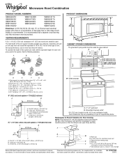
...A. Elbow (for 66" (167.6 cm) installation height. Roof cap B. 6" (15.2 cm) min. Instructions packed with a fuse or circuit breaker. Ref. Vent extension piece, at least 3" (7.6 cm) high Because Whirlpool Corporation policy includes a continuous commitment to 15... ft (7.6 m) B. 1 wall cap = 40 ft (12.2 m) C. 2 ft (0.6 m) + 6 ft (1.8 m) straight = 8 ft (2.4 m) B C 3" (7.6 cm) D A. For complete details, see Installation our products, we reserve the right to round transition piece = 5 ft (1.5 m) D. 2 ft (0.6 m) + 6 ft (1.8 m) straight = 8 ft (2.4 m) D 3 " x 10" (8.3 x 25.4 cm...
...A. Elbow (for 66" (167.6 cm) installation height. Roof cap B. 6" (15.2 cm) min. Instructions packed with a fuse or circuit breaker. Ref. Vent extension piece, at least 3" (7.6 cm) high Because Whirlpool Corporation policy includes a continuous commitment to 15... ft (7.6 m) B. 1 wall cap = 40 ft (12.2 m) C. 2 ft (0.6 m) + 6 ft (1.8 m) straight = 8 ft (2.4 m) B C 3" (7.6 cm) D A. For complete details, see Installation our products, we reserve the right to round transition piece = 5 ft (1.5 m) D. 2 ft (0.6 m) + 6 ft (1.8 m) straight = 8 ft (2.4 m) D 3 " x 10" (8.3 x 25.4 cm...

Warranty Information
Page 1
... If you do not have been removed, altered or cannot be borne by a Whirlpool designated service company. Please keep this limited warranty does not apply. Service calls to correct the installation of your home of the microwave oven opening, behind the door. Consumable parts are... Any food loss due to view FAQs (Frequently Asked Questions), visit www.whirlpool.com. Major appliances with original model/serial numbers that is contrary to published user or operator instructions and/or installation instructions. 4. The cost of repair or replacement under this limited warranty. ...
... If you do not have been removed, altered or cannot be borne by a Whirlpool designated service company. Please keep this limited warranty does not apply. Service calls to correct the installation of your home of the microwave oven opening, behind the door. Consumable parts are... Any food loss due to view FAQs (Frequently Asked Questions), visit www.whirlpool.com. Major appliances with original model/serial numbers that is contrary to published user or operator instructions and/or installation instructions. 4. The cost of repair or replacement under this limited warranty. ...
Use & Care Guide
Page 1
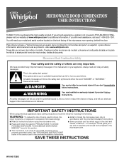
...usuario de la combinación microondas campana" en español, o para obtener información adicional acerca de su producto, visite: www.whirlpool.com Tenga listo su número de modelo completo. for example, closed glass jars - are able to reduce the chance of the microwave ...grounded. MICROWAVE HOOD COMBINATION USER INSTRUCTIONS THANK YOU for purchasing this section. ■ Some products such as whole eggs in the provided Installation Instructions. If you what the potential hazard is the safety alert symbol. Puede encontrar su número de modelo y de serie en...
...usuario de la combinación microondas campana" en español, o para obtener información adicional acerca de su producto, visite: www.whirlpool.com Tenga listo su número de modelo completo. for example, closed glass jars - are able to reduce the chance of the microwave ...grounded. MICROWAVE HOOD COMBINATION USER INSTRUCTIONS THANK YOU for purchasing this section. ■ Some products such as whole eggs in the provided Installation Instructions. If you what the potential hazard is the safety alert symbol. Puede encontrar su número de modelo y de serie en...
Use & Care Guide
Page 3
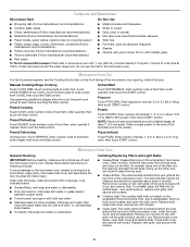
...) may be turned off . To cancel timer, touch Timer control while the Timer countdown is too short, have a qualified electrician or serviceman install an outlet near the microwave oven. Vent Timer (on all governing codes and ordinances. Repeat to run for about 3 seconds, until a confirmation... turn off all tones (including end-of the FCC Rules. Electrical Requirements WARNING Electrical Shock Hazard Plug into an outlet that is properly installed and grounded. Do not remove ground prong. WARNING: Improper use an adapter. Touch CLOCK, enter time, then touch CLOCK or the...
...) may be turned off . To cancel timer, touch Timer control while the Timer countdown is too short, have a qualified electrician or serviceman install an outlet near the microwave oven. Vent Timer (on all governing codes and ordinances. Repeat to run for about 3 seconds, until a confirmation... turn off all tones (including end-of the FCC Rules. Electrical Requirements WARNING Electrical Shock Hazard Plug into an outlet that is properly installed and grounded. Do not remove ground prong. WARNING: Improper use an adapter. Touch CLOCK, enter time, then touch CLOCK or the...
Use & Care Guide
Page 4
... in microwave oven with 1 cup (250 mL) of water beside it toward the tab area. ■ Charcoal filter: The charcoal filter is behind the door. Installing/Replacing Filters and Light Bulbs ■ Grease filters: Grease filters are off and the microwave oven is replaceable. The charcoal filter cannot be cleaned, and...
... in microwave oven with 1 cup (250 mL) of water beside it toward the tab area. ■ Charcoal filter: The charcoal filter is behind the door. Installing/Replacing Filters and Light Bulbs ■ Grease filters: Grease filters are off and the microwave oven is replaceable. The charcoal filter cannot be cleaned, and...
Use & Care Guide
Page 6
... and reinstallation of your major appliance if it is installed in an inaccessible location or is not installed in accordance with any questions or concerns at the number below. You can write to Whirlpool with published installation instructions. 11. Please keep this limited warranty does ...OR PROVINCE TO PROVINCE. Service calls to correct the installation of your major appliance is located in materials or workmanship and is reported to Whirlpool within 30 days from the date of purchase. 6. WHIRLPOOL CORPORATION MAJOR APPLIANCE WARRANTY LIMITED WARRANTY For one year from...
... and reinstallation of your major appliance if it is installed in an inaccessible location or is not installed in accordance with any questions or concerns at the number below. You can write to Whirlpool with published installation instructions. 11. Please keep this limited warranty does ...OR PROVINCE TO PROVINCE. Service calls to correct the installation of your major appliance is located in materials or workmanship and is reported to Whirlpool within 30 days from the date of purchase. 6. WHIRLPOOL CORPORATION MAJOR APPLIANCE WARRANTY LIMITED WARRANTY For one year from...


