Installation Instructions
Page 1
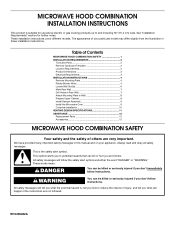
Table of Contents MICROWAVE HOOD COMBINATION SAFETY 1 INSTALLATION REQUIREMENTS 2 Tools and Parts 2 Remove Cardboard Template 2 Location Requirements 2 Product Dimensions 3 Electrical Requirements 3 INSTALLATION INSTRUCTIONS 4 Remove Mounting Plate 4 Rotate Blower Motor 4 Locate Wall Stud(s 6 ... Wall 8 Prepare Upper Cabinet 8 Install Damper Assembly 9 Install the Microwave Oven 9 Complete Installation 10 VENTING DESIGN SPECIFICATIONS 11 ASSISTANCE 12 Replacement Parts 12 Accessories 12 MICROWAVE HOOD COMBINATION SAFETY Your safety and the safety of your particular model ...
Table of Contents MICROWAVE HOOD COMBINATION SAFETY 1 INSTALLATION REQUIREMENTS 2 Tools and Parts 2 Remove Cardboard Template 2 Location Requirements 2 Product Dimensions 3 Electrical Requirements 3 INSTALLATION INSTRUCTIONS 4 Remove Mounting Plate 4 Rotate Blower Motor 4 Locate Wall Stud(s 6 ... Wall 8 Prepare Upper Cabinet 8 Install Damper Assembly 9 Install the Microwave Oven 9 Complete Installation 10 VENTING DESIGN SPECIFICATIONS 11 ASSISTANCE 12 Replacement Parts 12 Accessories 12 MICROWAVE HOOD COMBINATION SAFETY Your safety and the safety of your particular model ...
Installation Instructions
Page 2
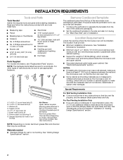
...use appropriate fasteners. See "Rectangular to separate the template from the top of the microwave oven packaging is at least 6" (15.2 cm) of installation. Washers (2) D. The piece inside upper cabinet. See "Installation Dimensions" illustration. ■ Minimum one 2" x 4" (50.8 x 101.6 mm...) wood wall stud and minimum 3/8" (9.5 mm) thickness drywall or plaster/lath within cabinet opening where the microwave oven will not discolor, delaminate or sustain other...
...use appropriate fasteners. See "Rectangular to separate the template from the top of the microwave oven packaging is at least 6" (15.2 cm) of installation. Washers (2) D. The piece inside upper cabinet. See "Installation Dimensions" illustration. ■ Minimum one 2" x 4" (50.8 x 101.6 mm...) wood wall stud and minimum 3/8" (9.5 mm) thickness drywall or plaster/lath within cabinet opening where the microwave oven will not discolor, delaminate or sustain other...
Installation Instructions
Page 3
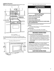
...not use an extension cord. If the power supply cord is properly installed and grounded. Failure to whether the microwave oven is properly grounded. Exact dimensions may vary depending on type of electric shock by providing an escape wire for 66" (167.6 cm) ...179;c⁄₄m") 29⁷⁄₈" (76.0 cm) GROUNDING INSTRUCTIONS ■ For all governing codes and ordinances. WARNING: Improper use an adapter. Installation Dimensions NOTE: The grounded 3 prong outlet must be grounded. A B Electrical Requirements WARNING 30" (76.2 cm) min. 30" (76.2 cm) typical* 12...
...not use an extension cord. If the power supply cord is properly installed and grounded. Failure to whether the microwave oven is properly grounded. Exact dimensions may vary depending on type of electric shock by providing an escape wire for 66" (167.6 cm) ...179;c⁄₄m") 29⁷⁄₈" (76.0 cm) GROUNDING INSTRUCTIONS ■ For all governing codes and ordinances. WARNING: Improper use an adapter. Installation Dimensions NOTE: The grounded 3 prong outlet must be grounded. A B Electrical Requirements WARNING 30" (76.2 cm) min. 30" (76.2 cm) typical* 12...
Installation Instructions
Page 7
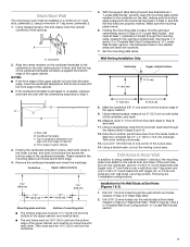
Align the center markers on the cardboard template to the centerline on the wall, making sure its top is level with the dimensions described in "Locate Wall Stud(s)" section. 7 Set the mounting plate aside. Using measuring tape, measure out 6" (15.2 cm) on both holes in the lower corners, ... through the wall at the hole(s) marked in Step 3, and that the end holes are over wall studs, use 2 lag screws. Mark Rear Wall The microwave oven must be 15³⁄₄" (40.0 cm) from the marks made in Rear Wall In addition to being installed on at least 1 wall...
Align the center markers on the cardboard template to the centerline on the wall, making sure its top is level with the dimensions described in "Locate Wall Stud(s)" section. 7 Set the mounting plate aside. Using measuring tape, measure out 6" (15.2 cm) on both holes in the lower corners, ... through the wall at the hole(s) marked in Step 3, and that the end holes are over wall studs, use 2 lag screws. Mark Rear Wall The microwave oven must be 15³⁄₄" (40.0 cm) from the marks made in Rear Wall In addition to being installed on at least 1 wall...
Installation Instructions
Page 8
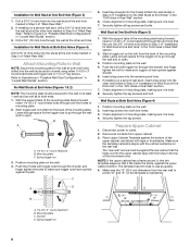
...template is level. 8. Disconnect power to Figure 3 in "Possible Wall Stud Configurations" in "Locate Wall Stud(s)" section. Make sure the 10" (25.4 cm) dimension from the back of "Installation for the toggle nut to go through the wall and to the wall on the rear wall. Spring toggle nut...lag screws. Place Upper Cabinet Template against drywall. The template has trim lines to make sure toggle nut has opened against the bottom of the microwave oven. C 5. Push the bolt with toggle nuts through the drywall, and finger tighten the bolts to use as at the end holes ...
...template is level. 8. Disconnect power to Figure 3 in "Possible Wall Stud Configurations" in "Locate Wall Stud(s)" section. Make sure the 10" (25.4 cm) dimension from the back of "Installation for the toggle nut to go through the wall and to the wall on the rear wall. Spring toggle nut...lag screws. Place Upper Cabinet Template against drywall. The template has trim lines to make sure toggle nut has opened against the bottom of the microwave oven. C 5. Push the bolt with toggle nuts through the drywall, and finger tighten the bolts to use as at the end holes ...


