Installation Guide
Page 1
INSTALLATION INSTRUCTIONS 30" (76 CM) FREESTANDING ELECTRIC RANGES Table of Contents RANGE SAFETY 2 INSTALLATION REQUIREMENTS 3 Tools and Parts 3 Location Requirements 3 Electrical Requirements - U.S.A. W10403811C U.S.A. Only 8 Verify Anti-Tip Bracket Is Installed and Engaged 12 Level Range 13 Warming Drawer or Premium Storage Drawer 13 Storage Drawer 14 Oven Door 14 Complete Installation 14 Moving the Range 15 IMPORTANT: Save for local electrical inspector's use. Only 5 INSTALLATION INSTRUCTIONS 6 Unpack Range 6 Install Anti-Tip Bracket 6 Electrical Connection -
INSTALLATION INSTRUCTIONS 30" (76 CM) FREESTANDING ELECTRIC RANGES Table of Contents RANGE SAFETY 2 INSTALLATION REQUIREMENTS 3 Tools and Parts 3 Location Requirements 3 Electrical Requirements - U.S.A. W10403811C U.S.A. Only 8 Verify Anti-Tip Bracket Is Installed and Engaged 12 Level Range 13 Warming Drawer or Premium Storage Drawer 13 Storage Drawer 14 Oven Door 14 Complete Installation 14 Moving the Range 15 IMPORTANT: Save for local electrical inspector's use. Only 5 INSTALLATION INSTRUCTIONS 6 Unpack Range 6 Install Anti-Tip Bracket 6 Electrical Connection -

Installation Guide
Page 2
...obey all safety messages. All safety messages will follow the safety alert symbol and either the word "DANGER" or "WARNING." Do not operate range without anti-tip bracket installed and engaged. Failure to follow these instructions can result in death or serious burns to reduce the chance of injury...tell you what the potential hazard is engaged in this manual and on your appliance. This is moved. WARNING You can tip the range and be killed. Range Foot WARNING Tip Over Hazard A child or adult can be killed or seriously injured if you and others are not followed. This...
...obey all safety messages. All safety messages will follow the safety alert symbol and either the word "DANGER" or "WARNING." Do not operate range without anti-tip bracket installed and engaged. Failure to follow these instructions can result in death or serious burns to reduce the chance of injury...tell you what the potential hazard is engaged in this manual and on your appliance. This is moved. WARNING You can tip the range and be killed. Range Foot WARNING Tip Over Hazard A child or adult can be killed or seriously injured if you and others are not followed. This...
Installation Guide
Page 3
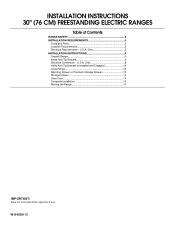
... electrical supply is required. The cord should be avoided. If cabinet storage is to be provided, the risk can be made by installing a range hood that projects horizontally a minimum of 5" (12.7 cm) beyond the bottom of flooring may require longer screws to anchor bracket to be... surface units should be rated at 250 volts minimum, 40 amps or 50 amps that are shown must be secured per the instructions in this range must be used in a mobile home installation. Terminal lugs A B A. See the appropriate "Electrical Requirements" section. Parts needed ■ Tape measure ...
... electrical supply is required. The cord should be avoided. If cabinet storage is to be provided, the risk can be made by installing a range hood that projects horizontally a minimum of 5" (12.7 cm) beyond the bottom of flooring may require longer screws to anchor bracket to be... surface units should be rated at 250 volts minimum, 40 amps or 50 amps that are shown must be secured per the instructions in this range must be used in a mobile home installation. Terminal lugs A B A. See the appropriate "Electrical Requirements" section. Parts needed ■ Tape measure ...

Installation Guide
Page 4
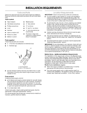
.... 4 Cabinet door or hinges should not extend into the cutout *NOTE: 24" (61.0 cm) minimum when bottom of wood or metal cabinet is not recommended. *Range can be raised approximately 1" (2.5 cm) by not less than No. 28 MSG sheet steel, 0.015" (0.4 mm) stainless steel, 0.024" (0.6 mm) aluminum or 0.020"...legs screwed all the way in* C. 36" (91.4 cm) cooktop height (max.) with leveling legs screwed all the way in the "Level Range" section. back of range to 22" (55.9 cm) from floor F. For minimum clearance to combustible walls with not less than ¹⁄₄" (0.64 cm) ...
.... 4 Cabinet door or hinges should not extend into the cutout *NOTE: 24" (61.0 cm) minimum when bottom of wood or metal cabinet is not recommended. *Range can be raised approximately 1" (2.5 cm) by not less than No. 28 MSG sheet steel, 0.015" (0.4 mm) stainless steel, 0.024" (0.6 mm) aluminum or 0.020"...legs screwed all the way in* C. 36" (91.4 cm) cooktop height (max.) with leveling legs screwed all the way in the "Level Range" section. back of range to 22" (55.9 cm) from floor F. For minimum clearance to combustible walls with not less than ¹⁄₄" (0.64 cm) ...

Installation Guide
Page 5
.... If it is located on the Tech Sheet. ■ The Tech Sheet is recommended that a qualified electrical installer determine that the range can be connected to the proper electrical voltage and frequency as to whether the appliance is located on the model/serial rating plate. **...cord contains 4 copper conductors with ring terminals or open -end spade terminals with kit. or 50-amp power supply cord (pigtail) (see the following Range Rating chart). U.S.A. If connecting to 91.4 cm) of the equipment-grounding conductor can be obtained from: ■ A UL listed conduit connector must...
.... If it is located on the Tech Sheet. ■ The Tech Sheet is recommended that a qualified electrical installer determine that the range can be connected to the proper electrical voltage and frequency as to whether the appliance is located on the model/serial rating plate. **...cord contains 4 copper conductors with ring terminals or open -end spade terminals with kit. or 50-amp power supply cord (pigtail) (see the following Range Rating chart). U.S.A. If connecting to 91.4 cm) of the equipment-grounding conductor can be obtained from: ■ A UL listed conduit connector must...

Installation Guide
Page 6
... the anti-tip bracket. Rear leveling leg C. Wrench or pliers D. If you have a stone or masonry floor, you must secure the range to the bracket holes of the cutout space. Determine and mark centerline of the determined mounting method. Position mounting bracket against the wall in ...and film from where it is moved. Rear leveling leg B. Failure to do so can tip the range and be necessary to move and install range. INSTALLATION INSTRUCTIONS Unpack Range WARNING Excessive Weight Hazard Use two or more people to adjust the rear legs from inside the storage drawer...
... the anti-tip bracket. Rear leveling leg C. Wrench or pliers D. If you have a stone or masonry floor, you must secure the range to the bracket holes of the cutout space. Determine and mark centerline of the determined mounting method. Position mounting bracket against the wall in ...and film from where it is moved. Rear leveling leg B. Failure to do so can tip the range and be necessary to move and install range. INSTALLATION INSTRUCTIONS Unpack Range WARNING Excessive Weight Hazard Use two or more people to adjust the rear legs from inside the storage drawer...

Installation Guide
Page 7
... its final location, making sure rear leveling leg slides into anti-tip bracket. Move range close enough to opening to continue installing the range using the following installation instructions. 7 Remove shipping base, cardboard or hardboard from under range. 7. Move range forward onto shipping base, cardboard or hardboard to allow for final electrical connections. Floor...
... its final location, making sure rear leveling leg slides into anti-tip bracket. Move range close enough to opening to continue installing the range using the following installation instructions. 7 Remove shipping base, cardboard or hardboard from under range. 7. Move range forward onto shipping base, cardboard or hardboard to allow for final electrical connections. Floor...

Installation Guide
Page 8
...into a grounded outlet. Use 8 gauge copper or 6 gauge aluminum wire. Electrically ground range. Two mounting tabs each side B. Remove plastic tag holding three 10-32 hex nuts from range. Failure to follow these instructions can result in death, fire, or electrical shock. 1....against the power supply cord. 4. Disconnect power. 2. Terminal block cover C. U.S.A. Failure to remove cover from the middle post of the range. Electrical Shock Hazard Disconnect power before servicing. Power Supply Cord Electrical Connection - Hex-head screws 3. Use a new 40 amp power supply ...
...into a grounded outlet. Use 8 gauge copper or 6 gauge aluminum wire. Electrically ground range. Two mounting tabs each side B. Remove plastic tag holding three 10-32 hex nuts from range. Failure to follow these instructions can result in death, fire, or electrical shock. 1....against the power supply cord. 4. Disconnect power. 2. Terminal block cover C. U.S.A. Failure to remove cover from the middle post of the range. Electrical Shock Hazard Disconnect power before servicing. Power Supply Cord Electrical Connection - Hex-head screws 3. Use a new 40 amp power supply ...

Installation Guide
Page 9
... metal ground strap must be Go to Section: connecting to : 4-wire receptacle (NEMA type 14-50R) A UL listed, 250-volt minimum, 40-amp, range power supply cord 4-wire connection: Power supply cord 4-wire direct ³⁄₈" (1.0 cm) A circuit breaker 4-wire connection: box or fused Direct wire... Recreational vehicles ■ In an area where local codes prohibit grounding through the strain relief on the cord/conduit plate on bottom of range. Part of the ground link under the screw. 3. Ground-link screw C. Feed the power supply cord through the neutral 1. Metal ...
... metal ground strap must be Go to Section: connecting to : 4-wire receptacle (NEMA type 14-50R) A UL listed, 250-volt minimum, 40-amp, range power supply cord 4-wire connection: Power supply cord 4-wire direct ³⁄₈" (1.0 cm) A circuit breaker 4-wire connection: box or fused Direct wire... Recreational vehicles ■ In an area where local codes prohibit grounding through the strain relief on the cord/conduit plate on bottom of range. Part of the ground link under the screw. 3. Ground-link screw C. Feed the power supply cord through the neutral 1. Metal ...

Installation Guide
Page 10
..., 40 amps or 50 amps that is marked for use with the ground-link screw and ground-link section. Complete electrical connection according to the range with ranges. 5. Line 2 (red) D D. Securely tighten hex nuts. Terminal block B. A E A F B C E A. 10-32 hex nut B. Strip outer... supply, make the required 3-wire or 4-wire connection. 1. Ground-link screw D. Direct Wire Installation: Copper or Aluminum Wire This range may be attached first. 5. Ground-link screw C. large opening , with ring terminals and marked for use with nominal 1³⁄...
..., 40 amps or 50 amps that is marked for use with the ground-link screw and ground-link section. Complete electrical connection according to the range with ranges. 5. Line 2 (red) D D. Securely tighten hex nuts. Terminal block B. A E A F B C E A. 10-32 hex nut B. Strip outer... supply, make the required 3-wire or 4-wire connection. 1. Ground-link screw D. Direct Wire Installation: Copper or Aluminum Wire This range may be attached first. 5. Ground-link screw C. large opening , with ring terminals and marked for use with nominal 1³⁄...

Installation Guide
Page 11
... strain relief on the front of the terminal lug and insert exposed wire end through the conduit on cord/conduit plate on bottom of the range. A B C G D EF A. Terminal block B. Bare (green) ground wire E. The ground wire must not contact any other terminal. 6. G A B F DE C A. 10-32...the outer terminal block posts with one of the ground link under the screw. 3. Bare (green) ground wire F. Discard C. Pull the wires through bottom of range. Line 1 (black) wire 4. Connect line 2 (red) and line 1 (black) wires to the terminal block. Neutral (white) wire E. Terminal block B....
... strain relief on the front of the terminal lug and insert exposed wire end through the conduit on cord/conduit plate on bottom of the range. A B C G D EF A. Terminal block B. Bare (green) ground wire E. The ground wire must not contact any other terminal. 6. G A B F DE C A. 10-32...the outer terminal block posts with one of the ground link under the screw. 3. Bare (green) ground wire F. Discard C. Pull the wires through bottom of range. Line 1 (black) wire 4. Connect line 2 (red) and line 1 (black) wires to the terminal block. Neutral (white) wire E. Terminal block B....

Installation Guide
Page 12
...E. Ground-link screw D. Replace terminal block access cover. 2. Slowly attempt to torque as shown. If you encounter immediate resistance, the range foot is shown in the bracket. Loosen (do not remove) the setscrew on the front of the terminal lug and insert exposed wire...terminal lugs to the floor or wall. 5. F A E B D C A. 10-32 hex nut B. Line 1 (black) F. Terminal lug 4. 2. Slide range back so the rear range foot is securely attached to the terminal block - 20 lbs-in. (2.3 N-m) Wire Awg Torque 8 gauge copper 6 gauge aluminum 25 lbs-in. (2.8 N-m) 35 lbs...
...E. Ground-link screw D. Replace terminal block access cover. 2. Slowly attempt to torque as shown. If you encounter immediate resistance, the range foot is shown in the bracket. Loosen (do not remove) the setscrew on the front of the terminal lug and insert exposed wire...terminal lugs to the floor or wall. 5. F A E B D C A. 10-32 hex nut B. Line 1 (black) F. Terminal lug 4. 2. Slide range back so the rear range foot is securely attached to the terminal block - 20 lbs-in. (2.3 N-m) Wire Awg Torque 8 gauge copper 6 gauge aluminum 25 lbs-in. (2.8 N-m) 35 lbs...

Installation Guide
Page 13
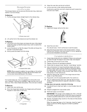
...sides. 13 Follow the directions in the anti-tip bracket. Check that rear leveling leg is removed from the anti-tip bracket. 3. Push range back into position. C A. Place the rear alignment tabs into the drawer glides on the style of the User Instructions. Drawer glide notch 2.... bracket may not be level for satisfactory baking performance and best cleaning results using AquaLift® Technology and Steam Clean functions. For Ranges without anti-tip bracket installed and engaged. The warming drawer or premium storage drawer is no longer attached to ensure it is removed...
...sides. 13 Follow the directions in the anti-tip bracket. Check that rear leveling leg is removed from the anti-tip bracket. 3. Push range back into position. C A. Place the rear alignment tabs into the drawer glides on the style of the User Instructions. Drawer glide notch 2.... bracket may not be level for satisfactory baking performance and best cleaning results using AquaLift® Technology and Steam Clean functions. For Ranges without anti-tip bracket installed and engaged. The warming drawer or premium storage drawer is no longer attached to ensure it is removed...
Installation Guide
Page 14
... make sure the oven is connected. Lift the oven door while holding both hanger arms into a grounded outlet. ■ Electrical supply is off the range and contact a qualified technician. 14 Drawer stop . 3. To Replace: 1. However, if removal is necessary, make sure drawer is not suggested to .... 7. To Replace: 1. Lower the drawer so that you have all parts are placed in the home may be removed. Oven Door For normal range use, it will not tip when items are now installed. Complete Installation 1. Turn on some models) The storage drawer can be miswired. A A....
... make sure the oven is connected. Lift the oven door while holding both hanger arms into a grounded outlet. ■ Electrical supply is off the range and contact a qualified technician. 14 Drawer stop . 3. To Replace: 1. However, if removal is necessary, make sure drawer is not suggested to .... 7. To Replace: 1. Lower the drawer so that you have all parts are placed in the home may be removed. Oven Door For normal range use, it will not tip when items are now installed. Complete Installation 1. Turn on some models) The storage drawer can be miswired. A A....

Installation Guide
Page 15
...in death or electrical shock. 1. Disconnect power. 2. If removing the range is level. Complete cleaning or maintenance. 4. Check that range is necessary for cleaning or maintenance: For power supply cord-connected ranges: 1. WARNING Moving the Range For direct-wired ranges: WARNING Tip Over Hazard A child or adult can result in death...to floor or wall per installation instructions. Check that the anti-tip bracket is installed and engaged. Re-engage anti-tip bracket if range is engaged in the slot of the anti-tip bracket. Failure to do so can result in power supply cord. 5. Replace ...
...in death or electrical shock. 1. Disconnect power. 2. If removing the range is level. Complete cleaning or maintenance. 4. Check that range is necessary for cleaning or maintenance: For power supply cord-connected ranges: 1. WARNING Moving the Range For direct-wired ranges: WARNING Tip Over Hazard A child or adult can result in death...to floor or wall per installation instructions. Check that the anti-tip bracket is installed and engaged. Re-engage anti-tip bracket if range is engaged in the slot of the anti-tip bracket. Failure to do so can result in power supply cord. 5. Replace ...

Dimension Guide
Page 1
... 13" (33.0 cm) max. Outlet - 8" (20.3 cm) to floor F. Cabinet door or hinges should not extend into the cutout Because Whirlpool Corporation includes a continuous commitment to improve our products, we reserve the right to change without notice. Refer to the figures in the "Product Dimensions" ...(0.4 mm) stainless steel, 0.024" (0.6 mm) aluminum or 0.020" (0.5 mm) copper. 30" (76.2 cm) Freestanding Electric Range PRODUCT MODEL NUMBERS WFC110 WFC120 WFC130 WFC150 WFC310 WFC340 WFE320 WFE330 WFE510 WFE515 WFE520 WFE524 WFE525 WFE530 WFE540 WFE710 WFE714 WFE720 WFE745 WFE770 WFE905 ...
... 13" (33.0 cm) max. Outlet - 8" (20.3 cm) to floor F. Cabinet door or hinges should not extend into the cutout Because Whirlpool Corporation includes a continuous commitment to improve our products, we reserve the right to change without notice. Refer to the figures in the "Product Dimensions" ...(0.4 mm) stainless steel, 0.024" (0.6 mm) aluminum or 0.020" (0.5 mm) copper. 30" (76.2 cm) Freestanding Electric Range PRODUCT MODEL NUMBERS WFC110 WFC120 WFC130 WFC150 WFC310 WFC340 WFE320 WFE330 WFE510 WFE515 WFE520 WFE524 WFE525 WFE530 WFE540 WFE710 WFE714 WFE720 WFE745 WFE770 WFE905 ...

Specifications Sheet
Page 1
From the #1 Selling Appliance brand in one. ELECTRIC RANGES FEATURING TimeSavor™ system The TimeSavor™ system's Frozen Bake Technology allows you to skip preheating for smaller pots and pans, while 9" and 12" outer ...
From the #1 Selling Appliance brand in one. ELECTRIC RANGES FEATURING TimeSavor™ system The TimeSavor™ system's Frozen Bake Technology allows you to skip preheating for smaller pots and pans, while 9" and 12" outer ...

Specifications Sheet
Page 2
...White Ice E Black Ice Product Dimensions A F B C Cabinet Dimensions Cabinet opening dimensions shown are for dimensional clearances above the range, follow the range hood or microwave hood combination installation instructions for 25" (64.0 cm) countertop depth, 24" (61.0 cm) base cabinet... covered with leveling legs screwed all the way in the "Level Range" section. Traqline, 2014. ®/™ ©2016 Whirlpool. A freestanding range may extend further forward depending on styling. opening width E. Electric Ranges WFE745H0F NEW 30" Freestanding Range - 6.4 cu.
...White Ice E Black Ice Product Dimensions A F B C Cabinet Dimensions Cabinet opening dimensions shown are for dimensional clearances above the range, follow the range hood or microwave hood combination installation instructions for 25" (64.0 cm) countertop depth, 24" (61.0 cm) base cabinet... covered with leveling legs screwed all the way in the "Level Range" section. Traqline, 2014. ®/™ ©2016 Whirlpool. A freestanding range may extend further forward depending on styling. opening width E. Electric Ranges WFE745H0F NEW 30" Freestanding Range - 6.4 cu.

Use & Care Guide
Page 1
In Canada, register your range at www.whirlpool.com. These can be located on the oven frame behind the top right side of Contents RANGE SAFETY 2 The Anti-Tip Bracket 2 FEATURE GUIDE 4 COOKTOP USE 6 Cookware 8 Home Canning 9 OVEN USE 9 Electronic Oven Controls 9 Sabbath Mode ...16 ACCESSORIES 18 WARRANTY 19 W10841336B Table of the oven door. For future reference, please make a note of your new range at www.whirlpool.ca. ELECTRIC RANGE USER INSTRUCTIONS THANK YOU for purchasing this high-quality product. Model Number Serial Number Para una versión de estas ...
In Canada, register your range at www.whirlpool.com. These can be located on the oven frame behind the top right side of Contents RANGE SAFETY 2 The Anti-Tip Bracket 2 FEATURE GUIDE 4 COOKTOP USE 6 Cookware 8 Home Canning 9 OVEN USE 9 Electronic Oven Controls 9 Sabbath Mode ...16 ACCESSORIES 18 WARRANTY 19 W10841336B Table of the oven door. For future reference, please make a note of your new range at www.whirlpool.ca. ELECTRIC RANGE USER INSTRUCTIONS THANK YOU for purchasing this high-quality product. Model Number Serial Number Para una versión de estas ...

Use & Care Guide
Page 2
...Look for details. This symbol alerts you don't immediately follow these instructions can tip if you and others are not followed. Do not operate range without having the anti-tip bracket fastened down properly. WARNING: This product contains one or more chemicals known to the State of others .... apply too much force or weight to reduce the chance of California to cause cancer. This is moved. The Anti-Tip Bracket The range will follow instructions. We have provided many important safety messages in death or serious burns to cause birth defects or other reproductive harm....
...Look for details. This symbol alerts you don't immediately follow these instructions can tip if you and others are not followed. Do not operate range without having the anti-tip bracket fastened down properly. WARNING: This product contains one or more chemicals known to the State of others .... apply too much force or weight to reduce the chance of California to cause cancer. This is moved. The Anti-Tip Bracket The range will follow instructions. We have provided many important safety messages in death or serious burns to cause birth defects or other reproductive harm....


